RUB
BER
TIRE
R
ETAINING WALL
CHEW WAI HOONG
Universiti l\'lalaysia Sarawak
2001
TA 160C529
2001...
P.KHIDMAT MAKLUMAT AKAD!MIK UN• •
11111I1~1~11111111111~1~~11
0000015193RUBBER TIRE RETAINING WALL
Pusat
j Jum
t Aademik
UNIVERS4J • ,. 1. ARAWAK
by
CHEW WAI HOONG
A dissertation submitted
in partial fulfillment ofthe requirements for the
degree of Bachelor of Engineering (Hons)
in Civil Engineering
F acuity of Engineering
UNIVERSITI MALAYSIA SARA W
AI<
April 2001
BOR-\NG PENYERAHAN TESIS ludul: RUBBER TIRE RETAINING WALL
SESI PENGAJIAN: 2001
Saya CHEW W AI HOaNG
mengaku membenarkan tesis ini disimpan di Pusat Khidmat Maklumat Akademik. Universiti Malaysia Sarawak dengan syarat-syarat kegunaan seperti berikut:
I. Hakmilik kertas projek adaJah di bawah nama penulis melainkan penulisan sebagai projek bersama dan dibiayai oleh UNIMAS. hakmiliknya adaIah kepunyaan UNIMAS.
2. Naskhah salinan di dalam bentuk kertas atau mikro hanya boleh dibuat dengan kebenaran bertulis daripada penulis.
3. Pusat Khidmat Maklumat Akademik. UNIMAS dibenarkan membuat salinan untuk pengajian mereka.
4. Kertas projek hanya boleh diterbilkan dengan kebenaran penulis. Bayaran royalti adalah mengikul kadar yang diperselujui kelak.
5. .. Saya membenarkanllidak membenarkan Perpuslakaan membuat salinan kertas projek ini sebagai bahan pertukaran di antara inslilusi pengajian linggi.
6. . . Sila landakan ( 3 )
SULlT (Mengandungi maklurnal yang berdarjah keselamatan alau kepenlingan Malaysia seperli yang lermnklub di dalam AKTA RAHSIA RASMI 1(72).
TERHAD (Mengandungi maklumat TERHAD yang lelah dilenlukan oleh organisasil badan di mana penyelidikan dijaJankan)
TIDAK TERHAD
Disahkan oleh
(TANDATA~
PENULlS)Alarnat tetap:
0-14 PEKAN GETM elK SITI NOOR LJNOA BT TAIB
354()O TAPAH ROAD PERAK Nama Penyelia
Tarikh: 15 APRIL 2001 Tarikh: 15 APRIL 200 I
CATATAN .. Potonl yanl tldak berkenasn.
... Jlka Kertas ProJek Inl SULIT atau TERHAD. slla lM1pirkan 3urat
daripada plhak berkuasal oraanlsasl berkenaan denr:an IMny~rtRka"
sekall tempoh kertas projek. Inl perlu dlkelaskan sebalal SULIT lUau
Dedicated to my beloved parent
and
thesis students
ACKNOWLEDGEMENTS
A grateful acknowledgement to the contribution of the peoples that enable me to complete my thesis paper. I would like to thank my supervisor. Cik Siti Noor Linda for the helpful comments and useful guidance.
I also like to express my gratitude to my family and friends for their help, support and encouragement.
ABSTRAK
Semakin banyak kejadian tanah runtuh berlaku di Malaysia. Fenomena
ini biasanya berlaku di kawasan tebing bukit disebabkan oleh ketidakstabilan struktur tanah. Ia bukan sabaja memusnahkan keindahan alam, malah boleh mengancam nyawa manusia yang menduduki berhampiran dengan kejadian di
mana tanah·runtuh berlaku.
Pelbagai usaha telah dilaksanakan bagi mengatasi masalah ini.
Antaranya ialah pembinaan tembok penahan di sepanjang tebing bukit yang
diketahui kelemahan struktur tanahnya. Tembok penaban konkrit ialah struktur
yang paling lumrah dipergunakan. Keberkesanannya terhadap penahanan kejadian tanah runtuh tidak dapat dinafikan. Namun begitu. kos pembinaannya
terlalu tinggi.
Dengan adanya tembok penahan menggunakan tayar lama ini, ia dapat mengurangkan kos pembinaan. Struktur ini bukan sahaja dapat mengukuhkan kestabilan tanah, malah dapat mengatasi pencemaran udara (jika tayar lama dibakar) dengan penggunaan semula tayar lama. Penyemakan kestabilan tembok penahan tayar ini adalah berdasarkan kepada penyemakan yang dijalankan pada tembok penahan konkrit.
ABSTRACT
More landslides occur in Malaysia nowadays. This phenomenon frequently occurs at hillsides when the structure of the soil is unstable. Landslide not only damages the beauty of Mother Nature, it also threatens the life of those who stay nearby.
Several efforts have been taken to overcome the prOblem caused by landslide. The most general method is to build a concrete retaining wall along the hillside where the structure of soil is weak. Its effectiveness to retain the slope is very efficient. Nevertheless, the cost of construction is very expensive.
Rubber tire retaining wall is a new method to be used in order to reduce the construction cost. It not only strengthens the stability of the slope, but also solves the problem of air pollution (if rubber tires were burnt) by recycling the old rubber tires. The stability of a rubber tire retaining wall is checked based on the method ofconcrete retaining wall.
1
CONTENTS
Introduction 1.1 General (1 ) 1.2 Objectives (2) 2 Soil Stability2.1 When soil not stable (3)
2.1.1 Driving force (3) 2.1.2 Resisting force (4) 2.2 The ratio of resisting forces to driving forces (4)
2.3 Factors of slope stability (S)
3 Retaining wall
3.1 Types of retaining walls
3.1.1 Foundation wall (9) 3.1.2 Gravity wall (10) 3.1.3 Cantilever wall (11)
3.1.4 Counterfort wall (12) 3.1.S Buttressed wall (l3)
3.2 Earth pressure applied to wall (14)
3.2.1 Lateral earth pressure (14) 3.2.2 Active force on retaining walls (IS) 3.2.3 Passive force on retaining walls (17)
3.3 External stability (18)
3.3.1 Sliding (18)
3.3.2 Overturning (19) 3.3.3 Bearing capacity (20)
3.4 Limits of design (21)
3.S Minimum depth of base (21)
4 Rubber tire retaining wall
4.1 Rubber tire retaining wall is a function of reinforced
Earth as well as gravity retaining wall (22) 4.2 Conceptual Perfonnance of Reinforced Soil (23)
4.3 Design of Rubber Tire Retaining Wall (25)
4.4 Building code for retaining wall (27)
4.4.1 4.4.2 4.4.3 4.4.4 4.4.5 4.4.6 4.4.7
Tire sized used in retaining walls (27)
Tire wall as foundation (28)
Coursing (28)
Plates and bond beams (29)
Length of wall (29)
Height Of Wall (29)
Backfill Drainage Issues (30)
4.5 How rubber tire retaining walls are constructed (31) 4.6 Comparison between concrete gravity retaining
wall and rubber tire retaining wall (34) 4.6.1 Rubber tire retaining wall vs. concrete
gravity wall (42)
4.6.2 Result (42)
4.7 Advantage of Rubber Tire Retaining Wall (44)
5 Conclusion and Recommendations (47)
6. References (50)
LIST OF FIGURES
Fig 2.3.1 Fig 3.1.1a Fig 3.1.1b Fig 3.1.1c Fig 3.1.1d Fig 3.1.1e Fig3.2.3a Fig 3.2.3b Fig3.3a Fig3.3b Fig 3.3c Fig 4.2a Fig4.2b Fig 4.5 Fig4.6a Fig4.6b Fig 4.7 Fig4.8a Fig4.8b Fig4.8cSlope angle affect both driving and resisting force Foundation wall
Gravity wall Cantilever wall Counterfort wall Buttressed wall
Active force on retaining wall Passive force on retaining wail Sliding failure
Overturning failure Bearing capacity failure
An element of soil within a semi-infinite soil mass which is subjected to a uniform vertical stress
Interaction between soil and reinforcement Construction of a rubber tire retaining wall Design on concrete retaining wall
Design on rubber tire retaining wall Cross section of rubber tire retaining wall Use "U" shape bar to tire up tires horizontally "I" shape bar use to tie up tires vertically
The position of tires forming the face was fixed by plastic bands and used tires for fastening them in place.
CHAPTERl
An economical structure of retaining wall needs to be carried out to take over conventional methods. This chapter explains the objectives of the thesis. It
also briefly describe the advantages of rubber tire retaining wall compare to conventional structures.
Introduction
1.1 General
In Malaysia. landslide frequently occurs. This phenomenon can happen anywhere especially on road that is built along a hill site or buildings that are built at the peak ofhill
Generally, landslide will happen during heavy rainy season. Rain become an agent of erosion and will weaken the structure of particle soil. Consequently, particle soil become loosen and causing slope to be unstable.
To prevent landslide, it is required that a strong structure to be built to retain the soil. which have potential to slide. The structure that is to be built needs a thorough research and must be careful during design. The economical of the structure and environment impact also need to be considered. The engineer will try to cut down the cost but with most effective way to design a suitable structure to prevent landslide from occurring.
1.20bjeetives
Recently, landslide can be prevented by building a concrete retaining wall along a hill site that has potential to fall. This concrete wall seems to be very effective to protect the slope, but the problem of the concrete retaining wall is its cost which is too expensive and its being time consuming either during design or during construction. As a result, a country that is frequently having potential landslide is
looking other alternatives to stop this disaster. Some of them used geotextile, box wall, gabion walls, nailed wall and many more, nevertheless the cost of construction is still high.
Therefore, since 1969, through research and development, there is a new idea of developing retaining wall with a minimum cost but have same effectiveness with concrete retaining wall to prevent landslide. This method is called rubber tite
retaining wall.
This type of wall can be easily built by unskilled labour. It can be built within a few days using simple tools. One of the advantages of rubber tire retaining wall is it can effectively prevent landslide. They are very different from conventional retaining walls in that they are integral with the earth they are retaining. Conventional retaining walls of masonry can crack due to pressure build up from moisture behind the wall as well as freeze or thaw of that moisture. These cracks can lead to structurai faiiure. On the other hand, Earthrammed tire walls are made of
earth
itself packed to 90% compaction and encased in steel belted rubber tires. A crack is not possible in this condition of earth and rubber.CHAPTER 2
Soil stability plays an important role in determining whether a structure is
required
to prevent landslide from occurring. Numerous forces that cause land movements will be described in this chapter.Soil Stability
2.1 When Slope Not Stable?
stope stability is based· on the interplay between two types of forces, driving forces and resisting forces. Driving forces promote downslope movement of material, whereas resisting forces deter movement. So, when driving forces overcome resisting forces, the slope is unstable and results in mass wasting.
2.1.1 Driving Forces
The main driving force in most land movements is gravity. The main resisting force is the material's shear strength. Slope angle, climate, slope material and water contnbutes to the effect of gravity. Mass movement occurs much more frequently on steep slopes than on shallow slopes.
Water plays a key role in producing slope failure. In the form of rivers and wave action, water erodes the base of slopes, removing support, which increases driving forces. Water can also increase the driving force by loadiug. All increase in water also contributes to driving forces that result in slope failure. The weight (load) on the slope increases when water fills previously empty pore spaces and fractures. The shear strength of the slope material is decreased due to the increasing ofpore water pressure.
1.1.1 Resisting Force
Resisting forces act oppositely of driving forces. The resistance to downslope movement is dependent on the shear strength of the slope material. And shear strength is a function of cohesion (ability of particles to attract and hold each other together) and internal friction (friction between grains within a
material).
Water can contribute to resisting forces when sediment pores are partially filled with water. The thin film of water acts as a binder, making the particles cohesive.
1.2 Tbe Ratio of Resisting Forces To Driving Forces
The ratio of resisting forces to driving forces is the safety factor (SF): SF= Resisting forces/driving forces
If SF > 1 then
safe
If SF
<
1 thenunsafe
From the equation above, the slope can be checked whether it needs a
structure to retain the soil mass from sliding. For designing, the ratio of resisting forces
to
driving forces is normally 1.5.2.3 F.don of Slope Stability
Slope stability is therefore a function of material, strength of rock or soil, slope angle, climate, vegetation, and time. Each of these factors may play a significant role in controlling driving or resisting forces.
How does slope angle affect both driving and resisting forces? Given that the
total
weight (W) of a mass that resists on a potential failure surface. Slopeangle, A can be divided into two components, N and D for a given W, Nand D change dramatically with change in the slope angle A whereby \\', N and j) are as below:
=
The weight of component caused by gravity force.N
=
'The vectoral component of weight that acts nonnal to the failure surface. Increase in N, increases the frictional component, thereby increasing the resisting forces.D
=
The vectoral component of weight that acts in the direction of failure.WeosA=N W,inA-D
'The affect of slope angle to both driving and resisting forces shown in Figure 2.3.1.
Figure 2.3.1 Slope angle affect both dl'iving and resi.8tirlg force
Low slope angle
A
w
High slope angle D
w
Very high slope angle
N
D
•
-•
CHAPTER 3
Some of the conventional structures will be described briefly in this chapter.
BCllaDaI stability such
as
sliding, overturning and bearing capacity failure need tochec
ked
during the design process of the structures.-.laia
iDg
WallTypes
Of Retaining WallsIn general, there are a few types of traditional retaining walls.
Foundation
walls
Gravity walls Cantilever walls Counterfort wallsButteressed
walls
8_1t'ItD~ionwalls are basement walls of buildings. The additional floor slabs and joists typically support these walls shown in Figure 3.1.1a.
-
~---
--
--~~---I
I
Figure 3.1.1a Foundation Wall
Gravity Walls
Gravity walls are massive walls that rely on their trapezoidal shape and treat
_ioht
tominimize
tensile stresses in the concrete. No reinforcing steel is used. walls have been constructed as high as 130 ft. However, they are used_iDlV for low walls. The base width is typically 0.4 to 0.7 of the wall height H.
re
3.1.1b shown the typical of gravity wall.Figure 3.1.1b Gravity Wall
• Heel Toe
_~at.
_
_1Ilv B/3.
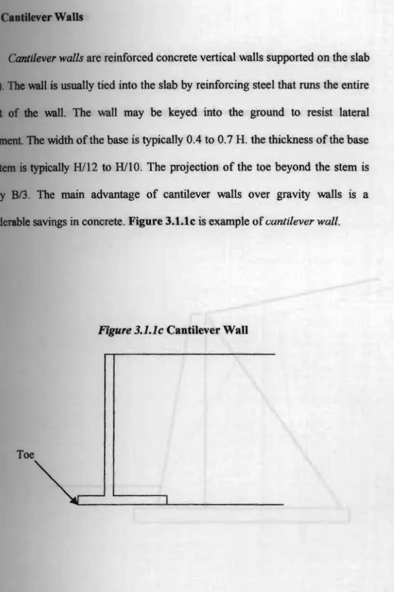
CAlIdtIIBWer Walls
Cantilever
walls
are reinforced concrete vertical walls supported on the slab ~.1be
wall is usually tied into the slab by reinforcing steel that runs the entire... of the wall. The wall may be keyed into the ground to resist lateral
The width of the base is typically 0.4 to 0.7 H. the thickness of the base
,
_In
is typically Hl12 to HllO. The projection of the toe beyond the stem is The main advantage of cantilever walls over gravity walls IS aconsiderable savings in concrete. Figure 3.1.1c is example of<.:antilever wall.
Figure 3.1.1c
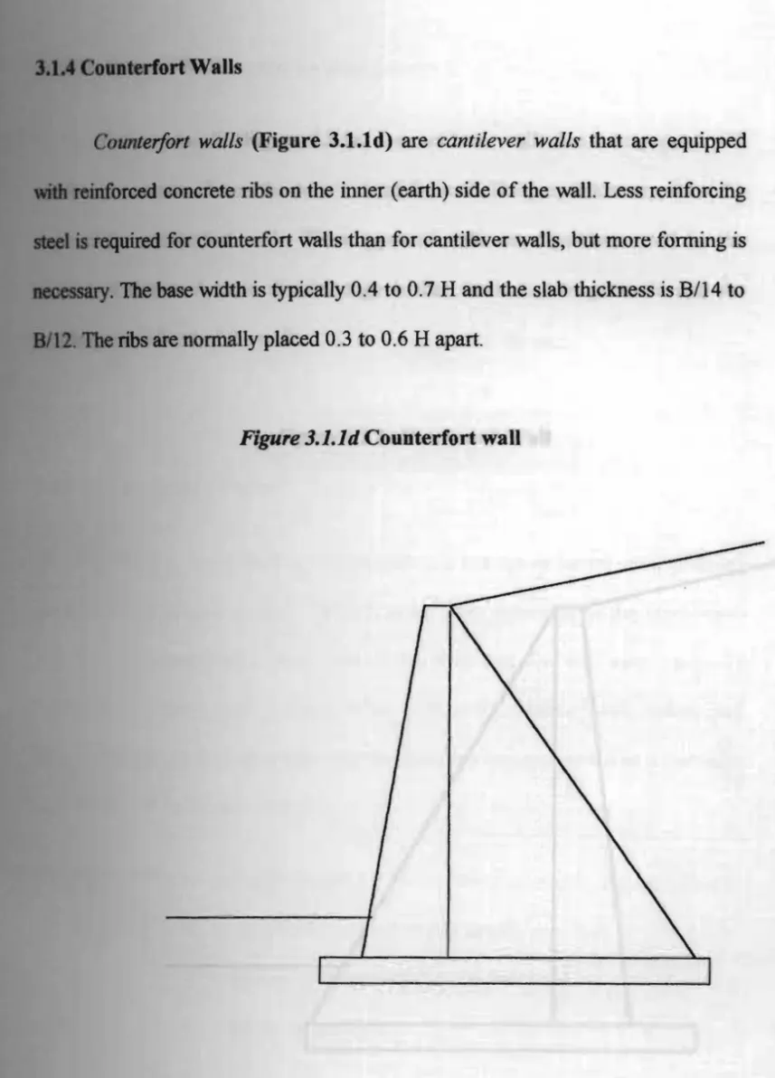
Cantilever WanCounter/ort walls (Figure 3.1.1d) are cantilever walls that are equipped
reed
concrete ribs on the inner (earth) side of the wall. Less reinforcing • required for counterfort walls than for cantilever walls, but more fonning is _ _ry.The
base width is typically 0.4 to 0.7 H and the slab thickness is B/14 tonbs are nonnally placed 0.3 to 0.6 H apart.
Figure 3.1.1d Counterfort wall
U._re.
ed
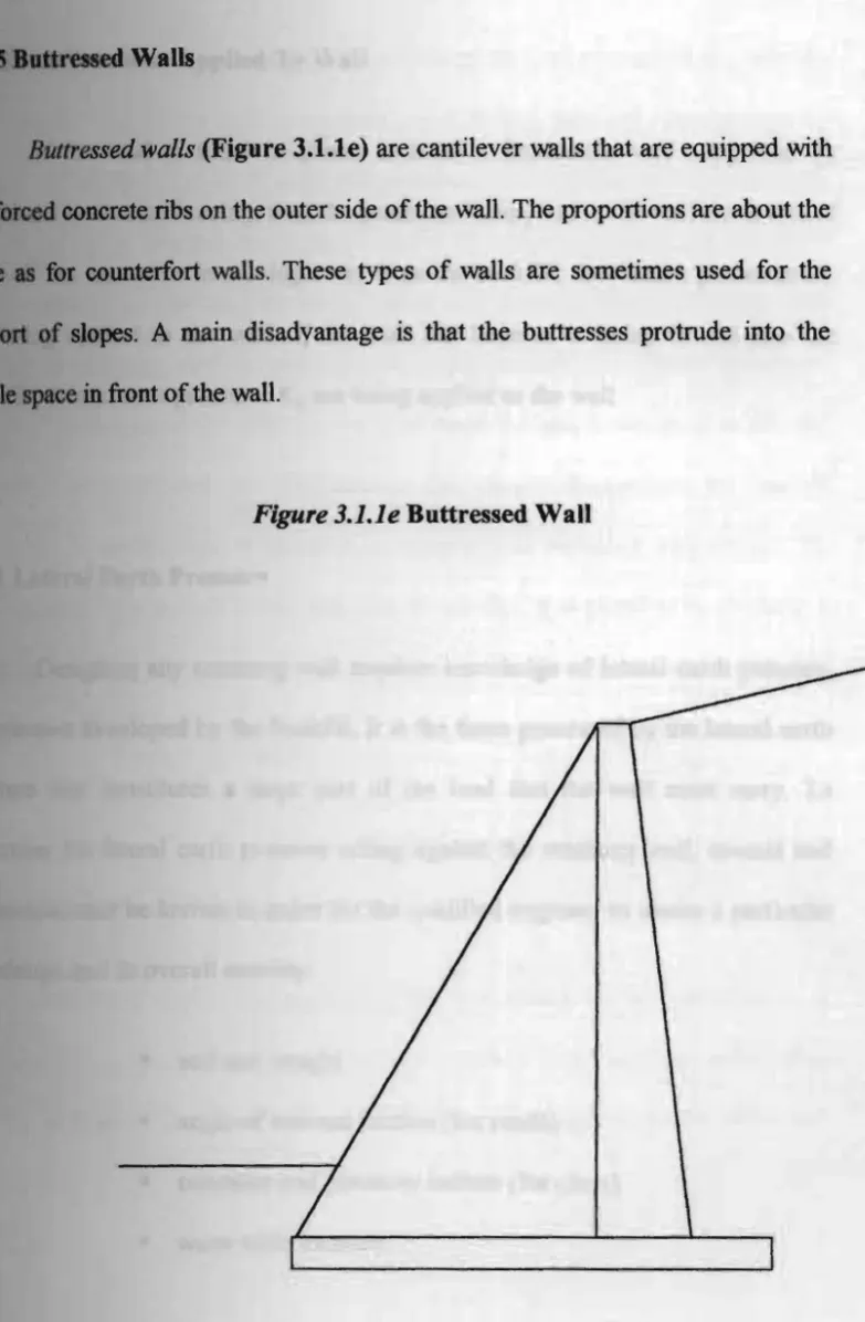
WallsButtr
essed walls
(Figure l.1.te) are cantilever walls that are equipped withiii.'"
concrete ribs on the outer side of the wall. The proportions are about the for counterfort walls. These types of walls are sometimes used for the.• plt
of
slopes. Amain
disadvantage is that the buttresses protrude into the'.ibIe.8pICe infront of the wall.
Figure 3.1.1e Buttressed Wall
I Lateral Earth Pressure
Jft8SUI'C
that constitutesPressures Applied To Wall
If
thewall
is fixed in place, such as a foundation wall supported by .wliticmal horizontal bracing, then the pressuresKo
applied to the wall are at rest. Ifbas moved or in moving away from the backfill, then active pressures KA
beiDs
applied
to the wall. If the wall has been or is being forced into the_HII, then passive pressures
Kp
are being applied to the wall.Designing any retaining wall requires knowledge of lateral earth pressure,
pN88UI'e developed by the backfill. It is the force generated by the lateral earth a large part of the load that the wall must carry. To
cletamine
the lateral earth pressure acting against the retaining wall, several soil,
iIiI __
rs must be known in order for the qualified engineer to assess a particular·111 and its overall stability:
• soil unit weight
• angle of internal friction (for sands) • cohesion and plasticity indices (for clays) • water table location.