About the Author
Donald Norris has a degree in electrical engineering and an MBA specializing in production
management. He is currently teaching undergrad and grad courses in the IT subject area at Southern New Hampshire University. He has also created and taught several robotics courses there. He has over 30 years of teaching experience as an adjunct professor at a variety of colleges and universities.
Mr. Norris retired from civilian government service with the U.S. Navy, where he specialized in acoustics related to nuclear submarines and associated advanced digital signal processing. Since then, he has spent more than 20 years as a professional software developer using C, C#, C + +, Python, Node.js, and Java, as well as 5 years as a certified IT security consultant.
Mr. Norris started a consultancy, Norris Embedded Software Solutions (dba NESS LLC), which specializes in developing application solutions using microprocessors and microcontrollers. He likes to think of himself as a perpetual hobbyist and geek and is always trying out new approaches and out-of-the-box experiments. He is a licensed private pilot, photography buff, amateur radio operator, avid runner, and, last but very important, a grandfather to a brand new baby girl—here’s to you,
Copyright © 2016 by McGraw-Hill Education. All rights reserved. Except as permitted under the United States Copyright Act of 1976, no part of this publication may be reproduced or distributed in any form or by any means, or stored in a data base or retrieval system, without the prior written permission of the publisher.
ISBN: 978-1-25-958789-4 MHID: 1-25-958789-4
The material in this eBook also appears in the print version of this title: ISBN: 978-1-25958833-4, MHID: 1-25-958833-5.
eBook conversion by codeMantra Version 1.0
All trademarks are trademarks of their respective owners. Rather than put a trademark symbol after every occurrence of a trademarked name, we use names in an editorial fashion only, and to the benefit of the trademark owner, with no intention of infringement of the trademark. Where such designations appear in this book, they have been printed with initial caps.
McGraw-Hill Education eBooks are available at special quantity discounts to use as premiums and sales promotions or for use in corporate training programs. To contact a representative, please visit the Contact Us page at www.mhprofessional.com.
Information has been obtained by McGraw-Hill Education from sources believed to be reliable. However, because of the possibility of human or mechanical error by our sources, McGraw-Hill Education, or others, McGraw-Hill Education does not guarantee the accuracy, adequacy, or completeness of any information and is not responsible for any errors or omissions or the results obtained from the use of such information.
TERMS OF USE
This is a copyrighted work and McGraw-Hill Education and its licensors reserve all rights in and to the work. Use of this work is subject to these terms. Except as permitted under the Copyright Act of 1976 and the right to store and retrieve one copy of the work, you may not decompile, disassemble, reverse engineer, reproduce, modify, create derivative works based upon, transmit, distribute,
disseminate, sell, publish or sublicense the work or any part of it without McGraw-Hill Education’s prior consent. You may use the work for your own noncommercial and personal use; any other use of the work is strictly prohibited. Your right to use the work may be terminated if you fail to comply with these terms.
THE WORK IS PROVIDED “AS IS.” McGRAW-HILL EDUCATION AND ITS LICENSORS MAKE NO GUARANTEES OR WARRANTIES AS TO THE ACCURACY, ADEQUACY OR COMPLETENESS OF OR RESULTS TO BE OBTAINED FROM USING THE WORK,
INCLUDING ANY INFORMATION THAT CAN BE ACCESSED THROUGH THE WORK VIA HYPERLINK OR OTHERWISE, AND EXPRESSLY DISCLAIM ANY WARRANTY, EXPRESS OR IMPLIED, INCLUDING BUT NOT LIMITED TO IMPLIED WARRANTIES OF
regardless of cause, in the work or for any damages resulting therefrom. McGraw-Hill Education has no responsibility for the content of any information accessed through the work. Under no
circumstances shall McGraw-Hill Education and/or its licensors be liable for any indirect,
incidental, special, punitive, consequential or similar damages that result from the use of or inability to use the work, even if any of them has been advised of the possibility of such damages. This
CONTENTS AT A GLANCE
1 Introduction
2 Getting Started with the Intel Edison Arduino Board 3 Working with Processing and the Intel Arduino IDE
4 Edison-Controlled Robotic Car
5 Connecting to Edison Linux with the Command-Line Prompt 6 Debian Linux and Python Basics
7 Python Classes, Methods, and the libmraa Library 8 Hardware Interfaces
9 Web Server and Database
CONTENTS
2 Getting Started with the Intel Edison Arduino Board Intel Edison Arduino IDE
3 Working with Processing and the Intel Arduino IDE
The Processing Language and the Intel Edison Arduino IDE Processing Language Basics
Summary
5 Connecting to Edison Linux with the Command-Line Prompt Intel Edison Breakout Board
Setting Up Your First USB Communications Session FTDI Drivers
How to Install the Debian Linux Distribution Step-by-Step Edison Debian Load Procedure
EMC Class Implementations
Apache Web Server and the PHP Scripting Language MySQL Database Installation
Adding a New User to a MySQL Database Python Database Connection
The Project Software sudo
The Project Stack
Initial Project Stack Test Battery Operations
Paho and Eclipse.org MQTT
Quality of Service (QoS) Wills
Reconnecting
Edison MQTT Publisher Client Auto Start
MQTT Brokers
MQTT Subscriber Clients
Mac MQTT Subscriber Client
Android Smartphone Subscriber Client Summary
PREFACE
This book will serve both as an introduction to the Intel Edison computing module and also as a reliable and concise Getting Started Guide for interested readers. This computing module was introduced at the Intel Developers Forum 2014 held in San Francisco on September 10, 2014. Intel described the Edison’s value as follows:
The Intel® Edison development platform is designed to lower the barriers to entry for a range of inventors, entrepreneurs, and consumer product designers to rapidly prototype and produce IoT and wearable computing products.
The Edison’s form factor, which will be described in detail later, is most definitely slated for applications demanding extremely compact hardware and, simultaneously, consuming miniscule power.
The Edison computing module is the latest in a progression of embedded technology devices that Intel has created over a long time frame. The Galileo Gen 2 development board was the most recent technology platform that just preceded the Edison. In many ways, the Galileo and Edison are quite similar except for one key aspect: The Galileo board may be used “as is,” meaning that all it needs is a power supply and interconnectivity to be accessed and operated. The Edison, on the other hand, requires some type of support board to provide both power and interconnectivity. The Edison’s need for a support board is the reason that I believe Intel labeled it as a computing module instead of a development board.
The Edison contains some remarkable hardware despite its very small size. It was purposefully designed to be used as a very capable embedded control module operating within an encompassing system. Intel’s design philosophy was to make the module extremely compact with ultra-low power consumption. These attributes make it ideal to function as a “wearable” computer, which is described in much greater detail later in the book.
1
Introduction
In this chapter, I will show you what makes up the Intel Edison computing module and introduce two
supporting development boards that will be used in programming the Edison as well as allowing it to connect with other system components.The Edison Computing Module
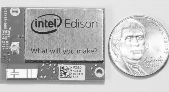
Figure 1-1 is a top view of the Edison module shown next to a U.S. nickel coin for a size comparison. It is quite small, barely larger than a typical U.S. postage stamp, with overall approximate dimensions of 34.9 × 25.4 × 3.2 mm. Under the metal cover is an Intel dual-core Silvermont Atom processor running at a 500-MHz clock speed. There is also a 100-MHz clocked Quark coprocessor included, which is designed to assist the Atom processor with input/output (I/O) operations. Unfortunately, as of the time of this writing, Intel has not released any software that will support the Quark
coprocessor; therefore, it will not be discussed any further in this book. I would suggest periodically checking the Intel Edison website, http://www.intel.com/edison to see if the Quark supporting
software has become available. I am sure that informative examples will also be provided to help you utilize the coprocessor.
There is also 4 GB of flash memory and 1 GB of RAM available to support the internal Edison processors. The flash memory comes preprogrammed with a Linux distribution created by Intel engineers using the Yocto framework. I will discuss this default Linux distribution in Chapter 2, in which I show you how to initially operate and communicate with the module.
There is also a Broadcom BCM43340 chip contained in the module, which implements b/g/n (11 Mbit/s, 56 Mbit/s, 100 Mbit/s internet speeds) and direct WiFi, as well as Bluetooth Low Energy (BLE) wireless communication. Both the WiFi and Bluetooth (BT) connections share the same onboard PCB chip antenna, which is visible at the lower left-hand corner in Figure 1-1. An external antenna connector using a μFL standard format is located just above the chip antenna and should be used if extended-range radio frequency (RF) operations are required. The internal chip antenna is fairly limited and will likely operate reliably only within 10 meters (m) of the WiFi access point, which is typically the wireless router in most home networks. Of course, BT communications was always designed to be close range, or not to exceed 10 m. One more point that you should know is that the antenna (internal or external) is multiplexed, or shared, between WiFi and BT operations. This might become problematic if maximum data bandwidth operations are attempted using both modes simultaneously.
The Broadcom chip also supports a hardware WiFi access-point (AP) mode, which might be very useful in certain applications. The only provision is that the module software must also support this type of operation. Fortunately, the default Linux distribution supports the AP mode, which allows for significant flexibility in configuring a network containing the Edison. Intel also provided support for BlueZ 5.0, which implements all the important and widely used BT profiles.
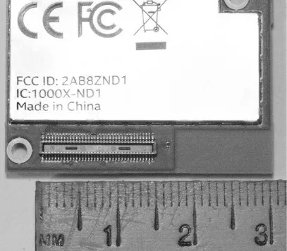
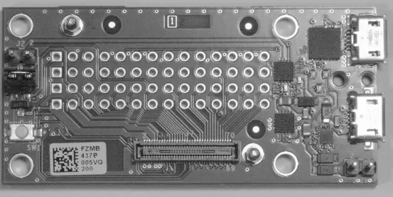
Figure 1-2 Bottom view of the Edison computing module.
I have already discussed what’s under the cover and will now focus on the connector. It is a 70-pin connector manufactured by the Hirose company. It is considered high density because of the very tight spacing between the connector pins, which are 35 pins spread across 14 mm with 0.4 mm
between pins. To put this in a common perspective, most hobbyist’s solderless breadboards have a 0.1-inch, or 2.54-mm, spacing between insertion points. The contacts on the Hirose connector are about six times closer than those on a breadboard. The practical meaning for this situation is that the Edison can be used only with a development board with the matching male connector already
installed on a PCB. It is just not feasible to manually solder 70 wires to a freestanding male Hirose 70-pin connector. It might be possible to solder a few wires to such a connector, using a magnifying lens and an extremely sharp-pointed soldering iron, but I think it is beyond my skill level as well as that of most of my readers. Another point worth mentioning is that the Hirose connector was not
designed to be inserted and removed frequently. You can do these operations a few times, but be very careful as it is easy to damage the connecting pins by misaligning them and/or using excessive force. I believe this will not be an issue for most readers, as they likely will just mount the Edison on an appropriate development board and simply use the board with their projects.
One very nice feature of the Edison, especially as compared to somewhat similar boards such as the Raspberry Pi, is that the Edison has 40 general-purpose input/output (GPIO) pins that are
available in the Hirose connector, in addition to the dedicated pins used for power and
Intel Arduino Development Board
An Arduino-compatible development board was designed by Intel to allow new users to quickly use the Edison module by taking advantage of the widely known and familiar Arduino integrated
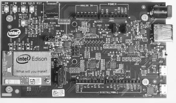
development environment (IDE). This development board uses the Edison module to replace the Atmel Atmega chip used in the “normal” Arduino board. A top view of the Intel Arduino
Development Board is shown in Figure 1-3 with the Edison already mounted on the board.
Figure 1-3 Top view of the Intel Edison Arduino Development Board.
This appears to be a fairly complex board, but looks can be deceiving. Most of the circuitry on the board is devoted to voltage-level shifters. It turns out that the Edison uses a core voltage of 1.8 V, while the typical Arduino development package uses both 3.3 V and 5 V. Therefore, voltage level shifters are required to make the Edison function properly and safely with the much higher voltages used in normal Arduino projects. This constraint must always be kept in mind, as applying 3.3 V or 5 V directly to any of the Edison pins will instantly destroy the module. The pins are simply not
protected against any inadvertent overvoltage, no matter how brief.
You should also notice that the board has sockets in place that support regular Arduino shields. Supposedly, this board will operate normal Arduino-compatible shields according to Intel marketing claims. However, it has been repeatedly reported on Edison development forums that certain shields do not function well, if at all, with this board. There are some good reasons for this situation, which I will discuss in a later chapter. For now, I would strongly suggest that you simply use a normal
to get the Edison up and running very quickly and without much effort.
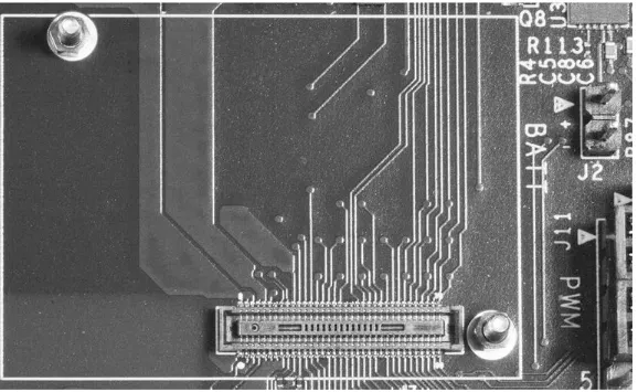
Figure 1-4 is a close-up photo of the board’s surface-mounted Hirose plug that plugs into the Edison. I included this photo to reinforce my discussion on the need to use a commercially prepared mounting system and to forgo any thought of creating your own. You can also see in this figure the two threaded posts that are used to hold the Edison in place. The threads on these posts are incredibly fine, so I strongly suggest that you do not lose the mounting nuts that came with the Edison module. I suspect you will not find any matching nuts in any local home-improvement store.
Figure 1-4 Intel Edison Arduino Development Board’s Hirose mounting plug.
I will discuss the various board connectors in Chapter 2, in which I show you how to get this board up and running. The next development board is really bare bones, but you will still be able to use it with the Edison, albeit not as easily as with the Intel Arduino Development Board.
Intel Edison Breakout Board
As mentioned earlier, this is a no-frills board that was designed by Intel to power on the Edison using the standard USB power pins, and to provide communication with the Edison using standard USB.
Figure 1-5 Top view of the Intel Edison Breakout Board.
There are four surface-mounted chips visible in the figure, two of which are dedicated to USB communication and the other two to USB voltage-level conversion between the standard 5-V USB signal levels and the Edison’s 1.8-V input/output levels. You can also see four rows of 14 plated-thru holes, which may be used to connect directly to the board-mounted Hirose connector. These PCB solder points allow you to connect directly to any of the Edison module pins. Remember, that no more than 1.8 V is allowed as an input. Exceeding that level will destroy the module. At this stage, with your limited exposure to the Edison, I would highly recommend that you avoid using any of these breakout pins.
Programming the Edison using this board will be deferred until a later chapter, as it involves using a direct Linux terminal application. I want to provide some additional background information before attempting to communicate with the Edison using this board.
Now, on to discussing the final Edison development support board in this chapter.
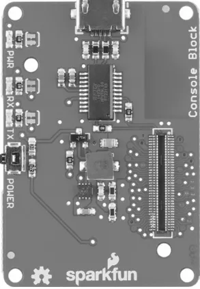
Sparkfun Block for Intel Edison–Console
Sparkfun (www.sparkfun.com) is a U.S. supplier specializing in open-source components and modules. At the time of Intel’s Edison product announcement, Sparkfun also announced that they would make available a series of boards that would support the Edison, including the following console board.
Figure 1-6 Top view of the Sparkfun Block for Intel Edison-Console DEV-13039.
Figure 1-7 Bottom view of the Sparkfun Block for Intel Edison-Console DEV-13039.
Table 1-1 Sparkfun Edison Support Boards
Figure 1-8 Example of a Sparkfun Edison board stack.
Later in this book I will demonstrate a simple board stack powered by the Battery board in a “wearable” project. This project will also provide a good example of the Edison’s low power
consumption, which allows for a cool operating system without the possibility of causing inadvertent heat injury to the person wearing the project.
Summary
I began the chapter with a brief description of what constitutes an Intel Edison computing module. The two internal processors were discussed as well as the impressive wireless communications modules, which provide WiFi and Bluetooth, simultaneously. The Hirose connector was also studied in detail, as that is a key component in how the Edison connects with any external development board or
module.
Three development boards were next described, starting with the Intel Arduino Development Board. I mentioned that the Intel Arduino board was probably the fastest and easiest way to start programming and using the Edison, especially for new users. This board uses the well-known and easy to master Arduino open-source integrated development environment.
The next board described was the Intel Edison Breakout Board, which really is quite minimalist as compared to the Arduino board. This board provides only power and USB communication between the Edison and a Linux-based terminal program running on an external laptop. This operational mode will be discussed in a later chapter.
Finally, I showed you one of the stackable Sparkfun boards that provides only USB and power to the Edison as did the previous board. However, you can combine several Sparkfun boards in a “so called” stack to provide many different functions to support a variety of projects.
2
Getting Started with the Intel Edison Arduino
Board
In this chapter, I will show you how to install and configure the Intel Edison Arduino integrated
development environment (IDE) so that you can connect with and program the Edison module that is connected to the Intel Edison Arduino Development Board. I will also discuss two ways to power the development board as well as two approaches for USB communication associated with this board.A simple LED-blinking example will also be demonstrated, which will prove that the IDE, the Edison, and the development board all function together as expected.
Intel Edison Arduino IDE
An Arduino IDE was created by Intel and specifically designed to operate with their Edison Arduino Development Board. This IDE is an emulation of the regular, open-source Arduino IDE that is
available from the http://arduino.cc website. The Intel version can be downloaded by going to
http://www.intel.com/edison and navigating to the Downloads & Documentation page. There are four versions of the IDE available in the Downloads page, and all were at revision 1.5.3 at the time of this writing. You should select the appropriate version that matches your host computer OS that you will use with the development board. I chose the Mac OS X version, as that matched my host system. There are 32- and 64-bit Linux versions available as well as a Windows version. Note that all the versions are compressed and will have to be extracted before the actual software can be installed on the host.
Figure 2-1 is an opening screenshot of the Intel Arduino IDE running on my MacBook Pro. You should notice that the IDE automatically creates a blank sketch template with a name containing the current day of the month, which, in this example, is sketch_jan09a. Also, note the IDE revision
Figure 2-1 Opening screenshot for the Intel Arduino IDE.
Powering the Arduino Development Board
Figure 2-2 Edge view of the development board.
There are two ways to power the development board:
1. Use the 2.1 mm barrel jack with a 7.5-V to 12-V external DC power supply.
2. Connect a powered USB cable to the OTG type B micro USB connector labeled J16 and located just to the left of the edge-mounted slide switch.
Connecting an external power supply to the barrel jack is the preferred way to supply power, especially if you plan on using wireless communications and/or if your project will need to supply a substantial amount of current through the GPIO pins. Providing power using a USB cable technically limits the board to a maximum current of 500 ma, which is the USB standard. The board itself will take about 200 ma when operating wireless communications, which leaves a maximum of 300 ma for all other requirements. Operating a single LED using a GPIO pin will typically consume anywhere from 20 to 30 ma, so you can see your current requirements rapidly accumulate. Straining a power supply can result in some very strange and odd development board behavior, so it is always wise to ensure that you have a stable and more than adequate power source.
NOTE It will not harm the board if you use the barrel connector for the main power supply and, at the same time, connect a powered USB cable to J16.
USB Communications
Figure 2-3 is a block diagram of the Intel Arduino Development Board in which you can see several USB ports diagrammed at the bottom, center of the figure.
Figure 2-3 Intel Arduino Development Board block diagram.
You will need to use the J16 micro USB connector as the link between the development board and the host computer. Notice that the line on the block diagram going between the USB Mux block and the Edison block is labeled as USB OTG, where OTG is an acronym for On-The-Go, a USB
specification issued in 2001. USB OTG allows USB devices, such as digital audio players or similar mobile devices, to act as a host, which allows other USB devices, such as thumb drives, to function with them.
The Edison implements the OTG specification, which allows it to both read from and write to a mass storage device, such as a thumb drive, as mentioned earlier. The Edison may also appear as a mass storage device when appropriately configured and connected to a host computer. In other words, the USB OTG specification allows a device to function either as a master or slave, depending upon the application. In the OTG configuration, the device controlling the USB communications link is referred to as the master, and the device being controlled, as the slave.
The OTG specification is the reason that the development board has two of the three USB
host configuration. Conversely, the micro “B” female connector to the immediate left of the slide switch will be the connector used if the board is in the slave or device configuration. Naturally, you must slide the switch to the appropriate side and use the proper connector to enable the desired OTG configuration.
Given all of the above background discussion, it is really important to know only that you must connect a micro-to-standard USB cable from J16 to the host computer with the slide switch pushed to the left
The remaining micro USB connector located on the far left of the board, as shown in Figure 2-2, is a USB UART connected to a serial FTDI chip, a configuration that would be used for a dedicated client-type application. The slide switch has no impact on this connector because it is always enabled (or not) through the Edison software.
It is time to demonstrate a simple Arduino program now that I have explained both the power and the USB communications aspects of the development board.
Program or Sketch
Code written in the Arduino/Processing environment is called a sketch. The name was chosen by the Processing open-source designers with the intention of playing off the artistic endeavors of sketching or drawing. I will use the term sketch or program interchangeably while discussing how to code using the Arduino IDE. However, I will use only the word, program, when I am coding outside of the Arduino/Processing environment.
Blink Sketch
The Blink sketch is an example program contained in a library that is readily available from the File menu in the IDE. You will need to connect both the power and USB cables to the development board and ensure that the slide switch is set to the left position, closest to J16 where the USB cable is plugged in. Ensure that the USB cable is plugged into the host computer. Next, follow these steps to load and run the Blink sketch:
1. Start the IDE application on the host computer, and you should see the display as shown in
Figure 2-1.
2. Select the Edison board by clicking Tools -> Board -> Edison
(Note You will get perplexing results by attempting to run the Blink sketch with the Galileo board selected.)
3. Select the appropriate serial port for your host computer. In my case, it was /dev/cu.usbmodem1d113 for the MacBook Pro. Click on Tools ->
Serial Port -> <your appropriate serial port> 4. Load the Blink sketch by clicking
You should now see the Blink sketch code displayed on the host, as shown in Figure 2-4.
Figure 2-4 Blink sketch.
right of the top edge of the Edison module. Recheck the IDE settings if you do not see a blinking LED. The most likely cause is either you did not select the Edison board or you have an incorrect serial port selected. Of course, you must be using the correct IDE. The regular Arduino IDE will not work with this development board, as I mentioned above.
It will next be a worthwhile exercise to modify the Blink sketch to slightly change its behavior. This activity will demonstrate how easy it is to make program changes and test them on the
development board. I will also explain some of the key features of this sketch, while showing you how to make the modifications.
Modifying the Blink Sketch
Prior to modifying the code, you will first need to load the Blink sketch into the IDE. All changes to the sketch are entered directly into the Editor pane, which displays the code. The following listing is a copy of the initial Blink sketch that was loaded from the default Examples library.
At the start of the listing are some descriptive words regarding what the sketch was designed to do. These are called comments and are differentiated from normal code in one of two ways.
2. A single line comment just follows these symbols //, as shown in this example:
Either single line comments are on their own line in the code, or they always follow any actual code and are terminated by a carriage return (CR) and line feed (LF).
It is always a good idea to include comments in your programs or sketches. It helps refresh your memory when you return to the program after some significant time lapse, and it also is very helpful for someone new to your program in interpreting what you wanted to accomplish with it.
There are two “parts” to this sketch that are common to all sketches. They are the setup and loop
methods and are shown in the code as follows:
and
The ellipses contained within the braces are simply placeholders representing the actual code. These two methods are also known as functions and may be thought of as code that collectively does something in support of the overall sketch behavior. The setup method as the name implies puts in
place certain preconditions that are necessary for the sketch to accomplish its stated purpose. In this case, the setup method changes GPIO pin 13 from its default input mode to an output mode so that it
can control an LED that is permanently connected to it on the development board. The setup method
is called or activated only one time, as that is all that’s needed for this configuration.
The next method is named loop, and as its name implies, is repeatedly called or activated for as
This method repeatedly blinks the LED on and off for a one second duration in each state. The Blink sketch is automatically compiled, downloaded to the development board, and executed by the underlying Arduino operating code that is activated when you click on the right-facing arrow in the IDE.
Let’s now modify the code so that the LED blink rate is twice as fast. Based upon my previous discussion, I believe you can see that this change can easily be accomplished by reducing the time delays from one second to one-half second for both the LED on and off times. In other words, changing both delay statements to:
I made these changes in the editor and then clicked on the arrow to observe the new behavior. I subsequently observed the LED blinking twice as fast after a few seconds delay while the sketch was recompiled and downloaded into the development board.
When you try to close the IDE, you will be prompted to save the modified sketch, as the IDE recognizes that changes were added. In this case, I elected not to save the modified sketch, as the changes were minor and could easily be added the next time I ran the Blink sketch. However, you will likely have a situation in the future in which you do make extensive modifications to a sketch and you should save it with a new name indicative of what the modified sketch accomplishes. For this previous example, I could envision changing the sketch name to FastBlink.
Summary
3
Working with Processing and the Intel Arduino
IDE
In this chapter, I will cover some of the basic concepts that are important in creating sketches that
can operate the Edison, using both the Intel Edison Arduino IDE and the Intel Arduino Development Board. I will also incorporate specifics related only to the Edison hardware, which should help focus and differentiate this chapter’s context from the myriad of other Arduino how-to-do-it books that are in the marketplace.The Processing Language and the Intel Edison Arduino IDE
Processing was the language created by the Arduino development team to program the original open-source Arduino hardware. It is based primarily on the C language, which has been in existence for many years and is still quite relevant for current embedded development projects. Processing also includes some object-oriented components, which makes it somewhat similar to the C++ language, but far less complex and comprehensive. The Intel software development team created an emulation of the original Arduino IDE so that it could program and operate the Edison module when it was attached to the Intel Edison Arduino Development Board, which I will, from now on, simply refer to as the dev board to save a lot of text entry.
The Intel and Arduino IDEs are different in their underlying make-up as I mentioned in the
previous chapter. The most important concept, which you should know, is that the Intel IDE creates a program that runs in the Edison’s Linux operating system and tries to function as a real hardware version of the Arduino. This concept is known as emulation and is not, and never can be, the same as real hardware. One of the consequences of emulation is that access to GPIO pins for reading and writing in their Processing implementation is much different from the original IDE Processing language implementation.
Again, as stated in the previous chapter, you cannot use the original Arduino IDE to program and run the Edison mounted on a dev board, nor can you use the Intel Edison IDE to program or run an Arduino board. The Intel Edison IDE along with its Processing implementation was really created to allow for rapid application development with the Edison by using a well-known and easily
understood programming environment. Another programming approach using the built-in Python language will be discussed later in this book. That approach is much faster and “cleaner,” as it does not depend upon an emulator to function.
The good news is that the Processing language is identical for both implementations when you program at a higher abstract level. This means the program logic can be created more or less independently of whether you are actually using a dev board or an Arduino.
are familiar with and comfortable programming the Arduino. However, there might be a tidbit or two in the following sections that will refresh your Arduino programming experience.
Processing Language Basics
Let’s start by stating that there are only three ways that a program will execute from start to finish. These are normally called flow of control and are listed below:
1. Step-by-step
2. Conditional (Selection) 3. Repetitive (Looping)
The first, step-by-step, is the default way a program operates. Program execution starts at the very first statement and then goes through every subsequent statement in the order in which the program statements were entered until the last or end program statement is encountered. What happens next is totally dependent upon the operating system (if any) that is being used to control the processor. I will cover this topic further when the repetitive flow of control is discussed.
The next type of control is termed conditional, or selection, and is frequently used when a
decision must be made regarding whether the execution stops being step-by-step and instead goes, or branches, to a specific location within the program. Most often, the if or if/else statements are
used to implement this behavior.
The last type of control is termed repetitive, or looping, which means that an instruction or group of instructions is repeatedly executed indefinitely, or until a specific condition is met. Sometimes the condition is an external event that signals the program to stop looping. The for and while statements
are most commonly used in creating a loop in Processing code. Looping may also be implemented in a method that is repeatedly called by an operating system or similar background process. The loop
method, which was first discussed in Chapter 2, is contained in every Arduino template. It simply repeats indefinitely until processor execution stops, or the power is interrupted.
I will next discuss input and output statements, as these are the most common types of operations that are executed by processors such as the Edison or Arduino.
Input and Output Statements
Turning input and output lines on or off are the tours de force, or main reasons, that embedded
Figure 3-1 Sparkfun’s Intel Edison pinout diagram.
If you look closely at this figure, you will see 40 pins that start with the label GP. These are the general-purpose input/output (GPIO) pins that are typically programmable as either an input or output. Note, that most pins also have another descriptor that follows the pin number. This is the default
behavior for that pin whenever the processor is powered on or reset. Also, not all of these GPIO pins are available on a particular development board, as it depends greatly upon what purpose the board is designed to serve. Most of the GPIO pins are available on the Arduino dev board, while none are available on the Sparkfun console board. However, remember that the console board is stackable so that all the GPIO pins, as well as the remaining 30 pins, are carried through the Hirose connectors to any other stacked boards. This means that any boards in the stack can break out the GPIO pins, as necessary, to carry out their designed function.
It is now important to clarify the dev board pin numbering prior to discussing the Processing
instructions that control the user-available pins on the board. There are 20 GPIO pins available on the shield sockets, which are shown in the figure and designated as IOxx. These are the exact pin numbers that you should use to manipulate the corresponding pins when writing a Processing sketch. All the alternate functions assigned to each pin are also clearly shown in the figure.
Table 3-1 Processing I/O Instructions
It is also critical to have memory locations to store and retrieve data. This is the purpose of data variables, which are discussed next.
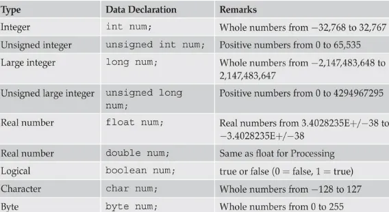
Data Variables
Table 3-2 Processing Data Types
While typical Arduino sketches do not normally require data to be displayed to the user, it is sometimes helpful to view real-time data and other information related to an executing sketch. Processing uses the string variable to store an array, or collection of characters, that may be displayed as either text or numeric information. Strings are declared and defined in several ways depending upon how they will be used in a sketch. Strings that are constant are declared as literals as follows:
A string that can hold variable text is simply declared as follows:
There are various ways that a string variable can have its text or numeric data assigned. Often, text and numeric data are programmatically generated and then added one character at a time to the string. Data may also be transferred directly into the string from a keyboard. How a string is populated really depends upon what purpose the sketch string serves and the design of the user interaction. No matter how strings are created, they are displayed to the user by the Serial Monitor, which is
activated by clicking on the magnifier glass icon located in the upper right-hand corner of the Arduino IDE. I will next present an example sketch that demonstrates most of the basic concepts that were just discussed, including how to use the Serial Monitor.
Average Voltage Measurement Sketch
This sketch will compute an average level for a signal waveform input. The level for a perfect sine wave signal should be 0.5 times the peak level of the sine signal, assuming that the sine wave is unipolar, i.e., there are no negative voltage levels and the downward peak is set at 0 V.
This sketch was designed to sample a sine wave signal at four times the input frequency, which should provide a good sampled representation of the input waveform. The sampling will also take place over a five-second duration, which will allow for 200 samples to be generated, given the 10-Hz input frequency.
Figure 3-2 10-Hz input sine wave.
Figure 3-3 AFG connection diagram.
Figure 3-4 is a screenshot of the Serial Monitor taken while the sketch was running. As you can readily see from the figure, the average level was 0.99 V, which is very close to the predicted 1-V average level for the input sine waveform. The level display is updated every five seconds, which was also preset in the sketch.
Figure 3-4 Serial Monitor screenshot.
The foregoing sketch demonstrated some key points with regard to creating an Arduino sketch. Variables were initially declared that held real-time data as well as the final results. An analog input was also used to sample the waveform, and an array of integers was set up to store 200 sample
values that were then used to compute the average signal level. Finally, the end result was displayed using the built-in Arduino IDE Serial Monitor.
Believe it or not, I have already covered most of the instructions that you will need to read sensors and/or control motors using the dev board. I just need to demonstrate one more relatively simple sketch that reads a switch and takes an action based upon the state of a switch, i.e., pressed or not pressed.
Switch Demo Sketch
This sketch is a modification of the Blink sketch with the addition of a pushbutton input. When the push button is pressed, the digital input will go from a high level to a low level, and a separate LED connected to pin IO2 will then start to blink twice a second for as long as the push button is pressed. Also, the LED connected to pin 13 will not blink when the push button is pressed.
You will need to wire a push button and a second LED with supporting resistors, as shown in
Figure 3-5 Fritzing wiring diagram for the Blink2 sketch.
Please note that I created a separate method named fastBlink to blink the LED connected to pin
2. This method is logically outside of the loop method; however, it will be called whenever the push
button is pressed. This approach to programming results in more readable and understandable code and should always be kept in mind.
My next sketch will demonstrate how to control an actuator, which, in this example, is a mini-servo. I am showing this sketch because I will be using servos in the Chapter 4 project and it would be useful for you to gain a little experience with this type of device.
Mini-Servo Sketch Example
with the dev board.
Figure 3-6 is a Fritzing diagram showing the connections between the servo, dev board, and a battery supply for the servo.
Figure 3-6 Mini-servo connection diagram.
Figure 3-7 Mini-servo connected to a dev board.
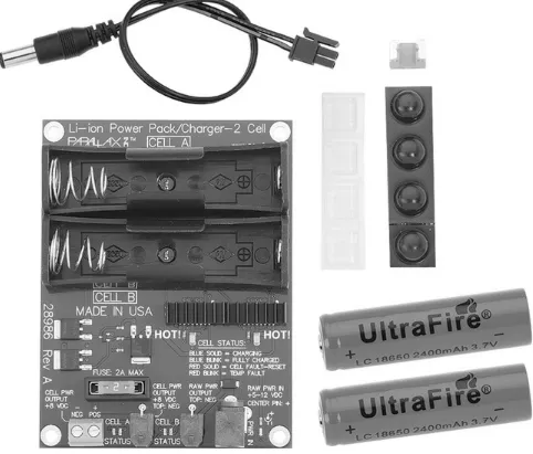
The servo power supply shown in the figure is a two-cell LiPo battery/charger board that was purchased from Parallax, where I also purchased the robot kit featured in Chapter 4. Each LiPo cell is 3.7 V, which, when connected in series, provides 7.4 V for the mini-servo. The battery board also provides a peak current in excess of 2 A, which is way more than the mini-servo requires.
This sketch contains several new programming techniques that are worth discussing. First, notice the statement near the top of the listing:
The ‘#’ symbol in front of the word include is a compiler directive that instructs the IDE to add a
special file named Servo.h, which contains all the needed attributes and method names used in a companion file named Servo.cpp. The extension .cpp indicates the latter file is a C++ file, containing an object-oriented (OO) template from which a Servo object can be instantiated. It is not my intention to go into depth on how to program with OO constructs, but it is important to realize what is
Immediately after the include directive comes the creation of a reference to a Servo object,
which is named myservo. Below is the instruction that accomplishes this task:
The reference, myservo, is an object of the Servo class from which a variety of methods may be
called. Calling a method in this fashion is done as follows:
This instruction associates pin 9 with the myservo object so that all subsequent digital commands
from the Servo object are directed to that pin. There can be many methods contained within the Servo class depending upon how its responsibilities are defined. Responsibility in this sense means how a class meets requirements imposed upon it during the design phase. The Arduino website is a great reference for determining what methods or behaviors are contained within a specific class. This reference is also known as an application programming interface (API) and should be used whenever you have a question regarding how a particular Arduino class can be used or modified. I have
included below a portion of the Servo class API for the attach method as an example of how useful the API is:
Obviously, the above code example does not function or accomplish anything other than to logically connect the myservo object to pin 9.
an ultrasonic ping distance sensor with the dev board. I elected to include it in this chapter to point out a key limitation contained within the Edison Arduino emulation as compared to a real hardware Arduino board. However, I will demonstrate a working sensor setup using an Arduino Uno board as a controller.
Ping Sensor Sketch
This sketch demonstrates my attempt to interface a fairly sophisticated sensor with the dev board using the Processing language. The sensor I used is called a Ping and is sold and distributed by Parallax. Figure 3-8 shows both an oblique front view and a rear view of this sensor.
Figure 3-8 Ping sensor views.
The piezoelectric transmitter and receiver are clearly visible on the front view, and a
Figure 3-9 Ping sensor operational block diagram.
Figure 3-10 Serial Monitor screenshot with Ping sketch running on the dev board.
I next connected an Arduino Uno to the sensor and loaded it with the same sketch. Note that I had to use the regular Arduino IDE to program the Uno. The Intel version does not work with the Arduino I, as had been mentioned in an earlier chapter. Figure 3-11 is a screenshot of the Serial Monitor with a book located exactly six inches from sensor transducer faces.
Figure 3-11 Serial Monitor screenshot with a Ping sketch running on an Arduino Uno.
Summary
4
Edison-Controlled Robotic Car
In this chapter, I will show you how to build a small robotic car that is controlled by the Intel
Edison Arduino Development Board (dev board). Some of the concepts and sketches discussed inChapter 3 will be put to practical use in this project.
BOE-BOT Car
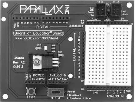
The robotic car used in this project is built from a Board of Education Robot (BOEBOT) kit, part number 32335, purchased from Parallax, Inc. They provide several kit versions supporting different microprocessor boards. This particular kit contains an Arduino Shield that allows for easy interface construction between the various drive components and the dev board, which is the controller for this project. Figure 4-1 shows the Arduino Shield, which mounts directly to the dev board.
Figure 4-1 Arduino Shield.
which is lacking on the dev board.
I also replaced the five-pack AA battery supply that is provided in the kit with a LiPo
battery/charger board with batteries, part number 28989, also available from Parallax. This battery board was initially discussed in Chapter 3 and is shown in Figure 4-2.
Figure 4-2 LiPo battery/charger board.
This particular battery board provides 7.4 V at a maximum of 2 A, which more than adequately meets the power source requirements for this project. The main power consumers are two continuous rotation servos that require about 250 ma each, when operating at full speed. The dev and shield boards each have their own voltage regulators that provide the proper voltages required for all board mounted components.
One minor problem in building this car by using the dev board is that the mounting-hole
Figure 4-3 Mounting plate adapter.
You will also need some additional spacers and 4-40 screws beyond what is contained in the original kit. I have described these additional parts in Table 4-1.
Table 4-1 Additional Hardware Required for the Robotic Car Assembly
You will need to follow the basic BOE_BOT assembly instructions, which are located on the Parallax website. I would recommend that you first mount the dev board to the LiPo board before you mount the LiPo board to the main chassis. You will need some free space to attach the mounting
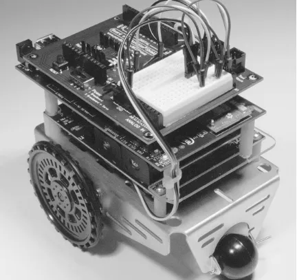
Figure 4-4 Assembled robot car.
You should note that at this point in the project there are no sensors attached to the car. I will add some in a later section, but at this stage, I just wanted to assemble and test a very basic car platform. Now it is appropriate to explain how an analog servo functions, as it will be hard to understand how the controlling sketch works without this background information.
How an Analog Servo Works
Figure 4-5 is a somewhat transparent view of the inner workings of a standard analog R/C servo motor. I would like to point out five components in this figure:
1. Brushed electric motor—left side 2. Gear set—just below the case top
3. Servo horn—attached to a shaft protruding above the case top
Figure 4-5 Inner view of a standard R/C servo motor.
The electric motor is just an inexpensive, ordinary motor that probably runs at approximately 12,000 r/min unloaded. It typically operates in the 2.5- to 5-V DC range and likely uses less than 200 ma, even when fully loaded. The servo torque advantage results from the motor spinning the gear set such that the resultant speed is reduced significantly, resulting in a very large torque increase, as compared to the motor’s ungeared rating. A typical motor used in this servo class might have a 0.1-oz-in torque rating, while the servo output torque could be about 42 0.1-oz-in, which is a 420 times increase in torque production. Of course, the speed would be reduced by the same proportional
amount, going from 12,000 r/min to about 30 r/min. This slow speed is still sufficiently fast enough to move the servo shaft to meet normal R/C requirements.
The feedback potentiometer attached to the bottom of the output shaft is a key element in
positioning the shaft in accordance with the pulses being received by the servo electronic control board. You may clearly see the feedback potentiometer in Figure 4-6, which is another image of a disassembled servo.
Figure 4-6 Disassembled servo showing the feedback potentiometer.
electronics board is the heart of the servo and controls how the servo functions. I will be describing an analog control version, since that is, by far, the most popular type used in low-cost servo motors.
Figure 4-7 shows a Hitec control board that is in place for its model HS-311, which is a very common and inexpensive analog servo.
Figure 4-7 Hitec HS-311 electronics board.
The main chip is labeled as HT7002, which is a Hitec private model number, as well as I could determine. I believe this chip functions the same as a commercially available chip manufactured by Mitsubishi with a model number of M51660L. I will use the M51660L as the basis of my discussion because it is used in a number of other manufacturer’s servo motors and would be representative of any chip that is used in this situation. The Mitsubishi chip is entitled a “Servo Motor Controller for Radio Control,” and its pin configuration is shown in Figure 4-8.
Figure 4-8 Mitsubishi M51660L pin configuration.
illustrates the key functional circuits incorporated into this chip.
Figure 4-9 M51660L Block Diagram.
I will next provide an analysis that will go hand-in-hand with the Figure 4-10 demonstration circuit that was provided in the manufacturer’s datasheet, as were the previous two figures.
Figure 4-10 Demonstration M51660L schematic.
This analysis should help you understand how an analog servo functions and why there are certain limitations inherent in its design.
1. The start of a positive pulse appearing on the input line (pin 5) turns on the R-S flip-flop and also starts the one-shot multivibrator running.
monostable, multivibrator circuit whose “on” time is proportional to the voltage appearing from the tap on the feedback potentiometer and the charging voltage from the timing capacitor attached to pin 2.
3. The control logic starts comparing the input pulse to the pulse being generated by the one-shot. 4. This ongoing comparison results in a new pulse called the error pulse, which is then fed to the
pulse stretcher, deadband, and trigger circuits.
5. The pulse stretcher output ultimately drives the motor control circuit that works in combination with the directional control inputs that originate from the R-S flip-flop. The trigger circuits enable the PNP transistor driver gates for a time period directly proportional to the error pulse.
6. The PNP transistor drive gate outputs are pins 4 and 12, which control two external PNP power transistors that can provide over 200 ma to power the motor. The M51660L chip can provide up to 20 ma without using these external transistors. That is too small a current flow to power the motor in the servo. The corresponding current sinks (return paths) for the
external transistors are pins 6 and 10.
7. The 560-kΩ resistor (Rf), connected between pin 2 and the junction of one of the motor leads and pin 6, feeds the motor’s back electromotive force (EMF) voltage into the one-shot. Back EMF is created within the motor stator winding when the motor is coasting or when no power pulses are being applied to the motor. This additional voltage input results in a servo damping effect, meaning that it moderates or lessens any servo overshoot or in-place dithering. I will also further discuss the Rf resistor when I cover the CR servo operation.
The above analysis, while a bit lengthy and detailed, was provided to give you an understanding of the complexity of what is constantly occurring within the servo case. This knowledge should help you determine what might be happening if one of your servos starts operating in an erratic manner.
There was the word “deadband” mentioned in step 3 that is worth some more explanation. Deadband used in this context refers to a slight voltage change in the control input that should not elicit an output. This is a deliberate design feature to prevent the servo from reacting to any slight input changes. Using a dead-band improves servo life and makes it less jittery during normal
operations. The deadband is fixed in the demonstration circuit by a 1-kΩ resistor connected between pins 9 and 11. This resistor forms another feedback loop between the pulse stretcher input and output.
The last servo parameter I will discuss is the pulse stretcher gain, which largely controls the error pulse length. This gain in the demonstration circuit is set by the values of the capacitor from pin 11 to ground and the resistor connected between pins 11 and 13. This gain would also be referred to as the proportional gain (Kp) in closed-loop control theory. It is important to have the gain set to what is sometimes jokingly called the “Goldie Locks region”, not too high nor too low, but just right. Too much gain makes the servo much too sensitive and possibly could lead to unstable oscillations. Too little gain makes it too insensitive and causes a very poor time response. Sometimes, experimenters will tweak the resistor and capacitor values in an effort to squeeze out a bit more performance from a servo; however, I believe the manufacturers have already set the component values for a good
balance between performance and stability.
Continuous Rotation (CR) Servos
Sometimes you will need a servo to act as a normal motor with the added advantage of being able to closely control both the speed and rotation direction. I have used continuous rotation (CR) servos for quite a long time in the robots I build for both classroom and personal use. You may easily purchase CR servos, or you can fairly easily convert a standard servo to a CR type. CR servos are almost identical in price to standard servos. I will explain the difference between the two, and you can decide if you want to convert or purchase.
The standard analog servo has a mechanical stop in place on a gear that is part of the main output shaft. This tab restricts the output shaft to a fixed range of motion, usually 180°. Figure 4-11 shows this mechanical stop on a standard servo gear train set.
Figure 4-11 Mechanical stop in a standard servo.
I would recommend trying to snap the tab off with a sharp diagonal cutter rather than filing it down. Be sure you disassemble the gear set before working on it because you don’t want any plastic shards or filings gumming up the gear train. Figure 4-12 shows the tab neatly removed and filed flat.
The next step in the conversion process is to remove the potentiometer by desoldering it from the circuit board. The potentiometer also has built-in stops, which would restrict the output shaft if it were not removed. The potentiometer must be replaced with a resistor divider circuit that supplies the mid-point voltage to the one-shot multivibrator. Figure 4-13 shows an altered demonstration schematic with two 2.2-kΩ resistors replacing the potentiometer.
Figure 4-13 Demonstration M51660L schematic altered for CR operation.
Now the control chip believes it is always at the center point; and when you supply an input pulse waveform with a width greater than 1.5 ms, the controller will drive the motor in a CW direction. Conversely, if the input pulse width is less than 1.5 ms, it will drive the motor in a CCW direction. Additionally, as you decrease or increase the pulse width, the motor will rotate faster in the
respective direction. This means 2.0 ms produces the maximum speed in the CW direction, while 1 ms produces the maximum speed in the CCW direction.
The only disadvantage is that the motor will tend to creep if your resistor divider doesn’t produce exactly the mid-point voltage. Exactly how much is hard to predict because the torque demands play a part in actually moving whatever object is being powered by the CR servos. A large robot would likely not even move due to the minute creep signal created. I would definitely use matched or precision resistors in order to divide the voltage as precisely as possible.
Another way to address this issue is to alter the value of the deadband resistor (the 1 kΩ) to help eliminate the undesired motion. It would be a trial and error process to determine the correct value.
There is one final precaution that you should know. It is entirely possible that the plus or minus 0.5 ms deviation from the center 1.5-ms pulse width will not produce the full rotation speed change that is possible. This is entirely due to having too large a value for the feedback resister Rf. The value set for this resistor in the demonstration circuit is 560 kΩ. This may have to be lowered to 120 kΩ to achieve the full speed capability for pulse widths that range from 1.0 to 2.0 ms.
Creating a sketch that controls CR servos requires an understanding of the Servo class write
write method with a CR servo.
Servo1 Sketch
I also want to mention why I used pins 3 and 9 to drive the servos in lieu of pins 12 and 13, which would normally be used for the sketch, since it was written for the Parallax kit using an Arduino Uno controller. The dev board does not appear to support analog servo control on any pins other than the pins I selected. I am unsure why this is the case, but I suspect it must be related to the underlying Edison GPIO pins that are brought out to the dev board shield pins. Just be aware that this is just another issue with using the dev board versus a real Arduino. And while addressing compatibility issues, I would also point out that the dev board does not appear to directly support the
writeMicroseconds(<number of microseconds>) method, which is part of the Servo class.
Again, this lack of functionality is likely related to the critical timing that I discussed earlier. Not being able to use the writeMicroseconds method just means that most of the example servo sketches
will not work with the dev board. They can be loaded into the board, but they will not function correctly.
The Servo write methods do appear to work correctly as I have demonstrated with my sample
Figure 4-14 Servo waveforms.
One pulse is 0.5 ms and the other is 2.5 ms, which, according to the API, will drive CR servos to maximum speeds in opposite rotational directions. This allows the robot car to move forward at its maximum speed, since the servos are mounted as mirror images.
Having now presented a working robot car, I will next show how to incorporate an obstacle sensor to provide a bit of autonomous operation to the car.
Autonomous Operation
Autonomous, or stand-alone, operation allows a robot to operate without direct user intervention. I will accomplish this by adding an ultrasonic sensor to the robot car that will be able to detect nearby obstacles and alert the robot controller, which is the dev board for this project. The ultrasonic sensor will be the same ping sensor discussed in Chapter 3. I will need to include a dedicated Arduino Uno to operate this sensor because the dev board does not operate it, as I discussed in Chapter 3. The Uno will be programmed to toggle a GPIO line if an obstacle is sensed within 10 inches or closer to the sensor transducers. The dev board is programmed to poll, or repeatedly test, this line to see if it has transitioned to a HIGH state. If it has, the sketch controlling the car will enter an obstacle avoidance routine, which, hopefully, will cause the robot to go on its way without a problem. This coding is actually a simple artificial intelligence (AI) approach that adds some autonomy to the robot’s behavior. Thus, the AI relieves a human operator from directly controlling the car, as would be the case for a typical radio-controlled (RC) vehicle.
Figure 4-15 Robot car wiring diagram.
Figure 4-16 Front view of the fully assembled robot car.
The ping sensor is plugged into a small, solderless breadboard, which is also mounted on an L-shaped piece of lightweight gauge aluminum stock. This bracket is attached to the car chassis by a pair of 3/8″ 4-40 machine screws and nuts.
Figure 4-17 Rear view of the car.
Operating the Robot Car
You start the car by simply sliding the shield slide switch from the 0 to the 1 position. You do not need to use the slide 2 position because the CR servos are connected to 5 V and not to Vin. After a delay of approximately 15 seconds, the car will move forward until it encounters an obstacle in its direct path. The car will then turn left about 45° and then attempt to go forward. If an obstacle is still detected, the car will turn further left another 45°. This should now normally provide a clear path forward for the car.
Summary
5
Connecting to Edison Linux with the
Command-Line Prompt
In this chapter, I will show you how to connect to an Edison module mounted on the Intel Edison
Breakout Board, which I will now simply refer to as the breakout board. I will be using a Macbook Pro running a terminal program as my client to the breakout board. I will also demonstrate some basic Linux commands sent to the Edison, which is running the default Poky Linux distribution.Intel Edison Breakout Board
I first showed you the breakout board in Chapter 1, but it did not have an Edison mounted on it. Figure 5-1 is a picture of the board with an Edison module mounted on it.
Figure 5-1 Intel Edison Breakout Board.
the breakout board: one for power and the other for USB serial communications. You are all set for a connection session, once you have the two cables connected between the breakout board and the laptop.
Setting Up Your First USB Communications Session
As mentioned earlier, I used a Macbook Pro as a client to connect with the Edison. The default
Terminal program on the Macbook served quite well as a client. If you are using a Windows or Linux computer, I would suggest using a free, open-source terminal program, such as TeraTerm. There are other similar applications available that I am sure would also function well as a client program.
FTDI Drivers
For your first connection, you will need to first install the FTDI drivers, which permit the client computer (the one running the terminal program) to connect to the host (the Edison). The host uses an FTDI chip to implement the USB communications, and these drivers establish virtual ports on the client. These virtual ports will be shown as Comm xx in the Windows Device Manager Ports section. The xx in the name will depend upon the number and type of comm ports already installed on the client computer. In a Mac computer, they will be identified as either tty.usbserial or
cu.usbserial followed by a long alphanumeric identifier. I discuss the Mac connection in more
detail in a following section.
These FTDI drivers may be downloaded from the Intel Edison downloads web page. As of the time of this writing, the driver is named CDM v2.10.00 and is approximately 2 MB in size.
Windows Drivers
Windows installations also require some additional drivers to implement RNDIS, CDC, and DFU. These drivers are also available on the Intel Edison downloads page. Just look for the selection entitled Windows Driver Setup. Click on this selection, and a file named
IntelEdisonDriverSetup1.0.0.exe will be downloaded to your computer. Just execute this file, and it will automatically complete the driver installations.
I have provided a brief description of these drivers below for those readers who might be interested.
• Remote Network Driver Interface Specification (RNDIS)—This driver creates a virtual Ethernet link over a physical USB connection. This link type is required to establish the initial USB communications with the Edison module.
• Composite Device Class (CDC)—This is a supporting class for RNDIS and is required for USB device recognition and communications.
• Device Firmware Upgrade (DFU)—This is an application that is used to update and upgrade the Edison’s firmware for Windows systems.
You will initially need to identify the logical device name that the Edison establishes when first connected. Use the following command to do this:
Figure 5-2 is a terminal screenshot for the results of this command. The name you will look for in a Mac OS X environment contains either cu.usbserial or tty.usbserial. The entry
/tty.usbserial-A502LTX2 was exactly what I needed.
Figure 5-2 Terminal screenshot displaying serial USB host names.
I next entered the following to establish the actual communications link:
The screen portion creates a session in the terminal application with the logically named device
tty.usbserial-A502LTX2 using a 115,200 baud rate. The -L at the end creates an automatic log file
that records all the session activity. This log file is very useful for troubleshooting problems that might arise with the communications link. I had to press the enter key twice to get the link working. This is due to an annoying problem with the Edison in which it will “go to sleep” after five seconds of inactivity on the USB serial line. Not a major issue; just an annoyance.
Figure 5-3 is a terminal screenshot of my second login with the Edison. I inadvertently terminated my first one by disrupting the power to the board
Figure 5-3 Terminal login screenshot.
You must enter root when prompted for a username and then simply press the return key when