Thermal performance of biomaterial wick loop heat pipes with
water-base Al
2
O
3
nano
fl
uids
Nandy Putra
a,*, Rosari Saleh
b, Wayan Nata Septiadi
a, Ashar Okta
a, Zein Hamid
a aHeat Transfer Laboratory, Department of Mechanical Engineering University of Indonesia, Kampus UI, Depok 16424, IndonesiabDepartemen Fisika, Fakultas MIPA-Universitas Indonesia, Kampus UI, Depok 16426, Indonesia
a r t i c l e
i n f o
Given the increase of heatflux generated by electronic equipment, particular components of a computer (e.g., the CPU) should always be accompanied with good cooling to achieve optimal operating capability and a high level of reliability. The use of loop heat pipes (LHPs) in the thermal management of electronic cooling is a major alternative solution. Before LHPs are implemented as an alternative cooling method for electronic devices, a quantity of reliability factors should be considered and evaluated, such as wick structure, material, and the type of workingfluid. In this case, the pore size distribution of a biomaterial (Collar) that is smaller and more homogeneous than pore size distribution of sintered powder was investigated. The purposes of this experimental study are to examine and analyze the application of a biomaterial (Collar) as a wick on a loop heat pipe and the use of the nanofluid Al2O3ewater as a working fluid. The performance of the biomaterial as a wick and nanofluid as a workingfluid in LHPs was also investigated in this experiment. The temperature differences between the evaporator and condenser sections with the biomaterial wick were less than that using a sintered copper powder wick, and the use of nanofluids over pure water also resulted in lower temperature differences; i.e., the thermal resistance of the LHP was lowered when using the biomaterial wick and nanofluids. These results make the biomaterial (Collar) and nanofluids attractive as wick and workingfluid, respectively, in LHP technology.
Ó2013 Elsevier Masson SAS. All rights reserved.
1. Introduction
Loop heat pipes (LHPs) are widely used in thermal management electronic cooling devices with high heatfluxes because of their high efficiency in heat transfer performance, small temperature differences, and because they contain no moving parts. An LHP is a two-phase device that has a very high and effective thermal con-ductivity that uses capillary forces inside the wicked evaporator to pump the workingfluid inside a closed loop[1]. LHPs have several excellent cooling capabilities and hold considerable promise for electronic cooling applications. Maydanik et al. [2] summarized some of the advantages of an LHP implementation in electronic cooling applications. LHPs have a higher capacity and a lower thermal resistance at comparable to other heatsinks, aflexibility in packaging, high heat transfer loads over considerable distances, and operate efficiently at any orientation in the gravitationalfield. There are many examples of LHP experimental developments and their implications in literature [1e6]. These studies indicate
that LHPs are nearly ready for commercial application. However, before LHPs are implemented as an alternative cooling method for electronic devices, several reliability parameters should be considered and investigated, such as wick structure and material and the type of workingfluid. The wick is the part of the heat pipe that circulatesfluid from the condenser to the evaporator. Hence, the wick has an important role both in conventional heat pipes and LHPs[7]. There are different types of capillary wick heat pipes, such as the screen mesh, sintered powder, groove, and the wire, all of which are made from metal, composites, and ceramics among other materials[7e14].
Many studies of wick characteristics have been conducted. For example, Li et al.[15]studied the ability of the wick to pump liquids (i.e., the capillarity of wick) on a sintered powder wick capillary. In their study, they found that the capillarity of the wick increases with an increasing porosity value of the wick. They also explained that in a typical real-time changing curve, there are three important parameters: the capillary pumping amount, the capillary pumping time and the capillary pumping rate. Leong and Liu [16] also studied the heat pipes capillary wick, which is made of a sintered powder concerning which the influence of sintering temperature (800C and 1000C). They also investigated sintering time on wick *Corresponding author.
E-mail address:[email protected](N. Putra).
Contents lists available atScienceDirect
International Journal of Thermal Sciences
j o u r n a l h o m e p a g e : w w w . e l s e v i e r . c o m / l o c a t e / i j t s
1290-0729/$esee front matterÓ2013 Elsevier Masson SAS. All rights reserved.
http://dx.doi.org/10.1016/j.ijthermalsci.2013.08.020
porosity. They concluded that a sintering temperature of 800C gave a better porosity value than a sintering temperature of 1000C. This was because the wick forms a solid stricter at 1000C. Consequently, less power capillarity will occur in the wick.
An assessment of wick sintered powder using nickel has been performed by Mishra et al.[17]. Their results showed that a sin-tering temperature of 775C produced the lowest porosity value, while at 550C produced the largest value. Zan et al.[18]analyzed the parameters of a loop heat pipe with a sintered powder wick and investigated the effect of wick porosity on the permeability of the wick to determine the amount of heat that can be absorbed by an LHP. An investigation on wick capillary action has also been per-formed by Tang et al.[19]using a thermal imaging method. In that study, they examined a groove wick, a sintered powder wick and a composite wick (sintered powder combined with the groove). The results indicate that the capillarity of the composite wick is higher than the capillarity of sintered powder wick and the groove wick.
Generally, sintered powder is used as a wick in heat pipe tech-nology. The wick structure determines the thermal performance of heat pipes because it provides the pumping force to return the
workingfluid to the evaporator. The secondary purpose of the wick is to distribute thefluid around the circumference of the tube to maximize the evaporator surface area[20]. Sintered porous struc-tures have attracted considerable attention over the last few de-cades because of their special properties, such as good permeability, high porosity andfine pore size[21]. Although sin-tered powder is generally very good and has many advantages over wire mesh and screen mesh, the manufacturing process is very difficult and time-consuming.
Collaria is a porous biomaterial that has a relatively small micropore size and a homogeneous pore size distribution. In its porous media, deposits of calcium carbonate are mainly produced by Collar in ordo scleractinia and sub-class Octocorallia. Collars usually form a colony that becomes a porous media with various dimensions. Given the homogeneous pore size distribution of its porous media, Collaria is expected to have a high permeability, porosity and capillary force, and the manufacturing process of us-ing biomaterials as a wick heat pipe is easier.
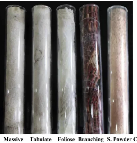
Many studies have been performed on LHPs, but there have not been any studies of LHP that use biomaterials as a wick. The pur-pose of this study was to investigate and characterize the applica-tion of biomaterials as a wick to improve the performance of LHP. Fig. 1.Samples of biomaterial and sintered powder capillary test.
Fig. 2.The method of capillary test.
Fig. 3.Capillary based on mass amount transported.
LHP wicks made from biomaterials and copper (Cu) metal powder sintering were tested under the same operational conditions. All of the wicks were of the same geometrical size, while the structural parameters depended on their characteristic. The performance of the nanofluid Al2O3ewater as a working fluid in LHP was also investigated in this experiment.
2. Research methodology
2.1. Design of capillary sample and testing
The maximum amount of workingfluid that can be pumped into a porous wick is called the capillary pumping amount, and it is one of the most important parameters of a porous wick. To know the capillary pumping amount of Collaria, samples were prepared in cylinder form, 13 mm in diameter and 100 mm in length. In this experiment, various Collaria types, such as Branching, Massive, Foliose and Tabulate, were tested. The sintered wick samples made of Cu powder of 200
m
m were prepared with varying of compaction pressures (4.6 MPa, 6.75 MPa, 9.38 MPa and 12 MPa). The sintering process was maintained at a temperature of 900C and the sin-tering time was 30 min. All samples were then inserted in a glass tube to ensure that the capillary action occurred only in axial di-rection, from the bottom to the top of the sample and easy to seethe motion of water in the samples. The use of difference tube material is predicted has no affect to the results.Fig. 1shows the samples of Collaria and sintered powder in glass tube.
In this study, we used Li et al.’s[15]method of measuring the capillary pumping parameter of a porous wick, the schematic dia-gram of which is shown inFig. 2. The method was performed by measuring the mass of liquid that can be transported in the porous media at a given time. To do this, a beaker is placed on an analytical balance and then pushed down the holder until the bottom of sample touched the surface of the workingfluid. When the porous wick reaches the surface of the workingfluid, it pumps working
fluid from the beaker due to capillarity. The reading of the elec-tronic analytical balance, which is connected to the computer, de-creases until the porous wick is saturated. The amount of working
fluid being pumped is equated to the reading reduction of the electronic analytical balance. The accuracy of the electronic balance used in this study is 0.1 mg. Capillarity measurement is carried out at atmospheric pressure.
The capillary pumping amount of the Collaria and sintered porous wicks are shown inFig. 3. It can be seen fromFig. 3that the capillary pumping amount of the sample Tabulate was the best, followed by Massive, Sintered, Foliose and Branching. Porous wicks with good capillary pumping amount are the best candidates for application in LHPs.
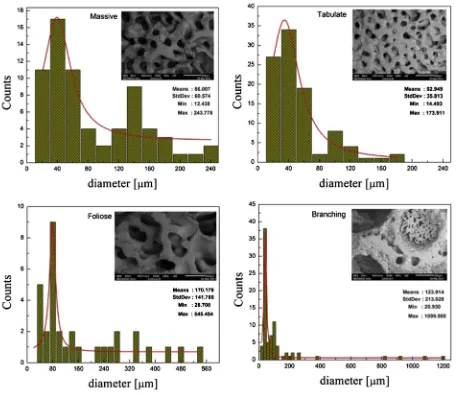
Fig. 4.SEM photograph and pore diameter distribution of biomaterial structure.
The micro-morphologies (SEM) of those samples, as shown in Fig. 4for types of coral samples andFig. 5for sintered wicks, were further studied to determine the causes of the pumping perfor-mances. It was found that the mean pore diameters of the Massive, Tabulate, Foliose and Branching were 83
m
m, 56m
m, 170m
m and 124m
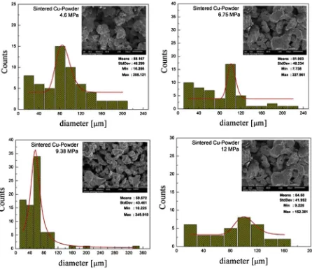
m, and the permeability of these samples was 510 15m2, 4.4010 15m2, 6.810 15m2and 7.810 15m2, respectively. The mean pore diameters of the sintered wick samples with vary-ing of compaction pressures 4.6 MPa, 6.75 MPa, 9.38 MPa and 12 MPa were 88m
m, 82m
m, 58.57m
m and 84.5m
m respectively.The porosity was determined based on Archimedes’principle as follows: the weight of the wicks in a dry state was measured, and then the pores were saturated with distilled water; finally, the
weights of the wicks saturated with water both in air andfloated in water were measured. The porosity (ε) of the wicks was calculated by the following:
PorosityðεÞ ¼ volume of pore wick
volume of porous media (1)
Fig. 5.SEM photograph and pore diameter distribution of sintered copper powder.
Table 1
Porosity of biomaterial wick and sintered powder.
No Wick material Porosity (ε) %
1 Tabulate 30.15
2 Massive 35.43
3 Foliose 49.75
4 Branching 63.32
5 S.P Cu 4.6 MPa; 900C; 30 min 47.49
6 S.P Cu 6.75 MPa; 900C; 30 min 44.47
7 S.P Cu 9.38 MPa; 900C; 30 min 39.95
8 S.P Cu 12 MPa; 900C; 30 min 15.82
Fig. 6.Loop heat pipe.
The porosity of the biomaterials and the sintered copper powder is shown inTable 1. The porosity of the wick depends on the pore radius of the porous media. The porosity of Massive Collaria was 35.43%, Tabulate was 30.15%, sintered copper powder at 9.38 MPa was 39.95% and sintered powder at 12 MPa was 15.82%. Based on the characteristic of corral wick and sintered copper powder wick, Tabulate and 9.38 MPa sintered copper powder were used as wick in LHP in this experiment.
High capillary forces which is favorable for a wicking materials are not only affected by their porous structure but also high surface wettability or a hydrophilic wick system plays also necessary roll to transport water in heat pipes. A water droplet will spreads on wick surface immediately and is pulled into their porous structure due to high capillary forces. But after exposure to room ambient air, they will gradually lose their hydrophilic property and eventually turn into hydrophobic surfaces. The reason for the loss of hydrophilicity in the heat pipe is oxidation.
2.2. Design of LHP
The LHPs consist of a copper tube of 8 mm in diameter. The evaporator side was manufactured using copper tube 20 mm in diameter and 100 mm in length. The jacket used as the condenser was 20 mm in diameter and 100 mm in length, with an annular gap through which the cooling liquidflow entered, after which it exited through two ends of the jacket, as shown inFig. 6. Theflow rates were considered constant. Three types of LHPs were made and tested: an LHP with a sintered Cu powder wick and biomaterial wick with length of wick are 50 mm and an LHP without a wick. The position of the wick can be seen inFig. 6. The wicks used were made of biomaterials of the Collaria Tabulate type, and the sintered copper powder was subjected to a compaction pressure of 9.38 MPa at sintering temperatures of 900C for 30 min, because their pore size distribution of biomaterial and the sintered powder in that condition is the smallest and most homogeneous compared to each type of wicks as shown inFigs. 4and5.
The workingfluids charged in the LHP were distilled water and nanofluids. In this investigation, aluminum oxide (Al2O3)
nano-particles 20 nm were dispersed in distilled water (H2O) as a base
fluid by ultrasonication at concentrations of 1%, 3%, and 5%. To consider the effects of nanofluid volume fraction, the concentra-tions were calculated using the following equation:
% volume fraction ¼
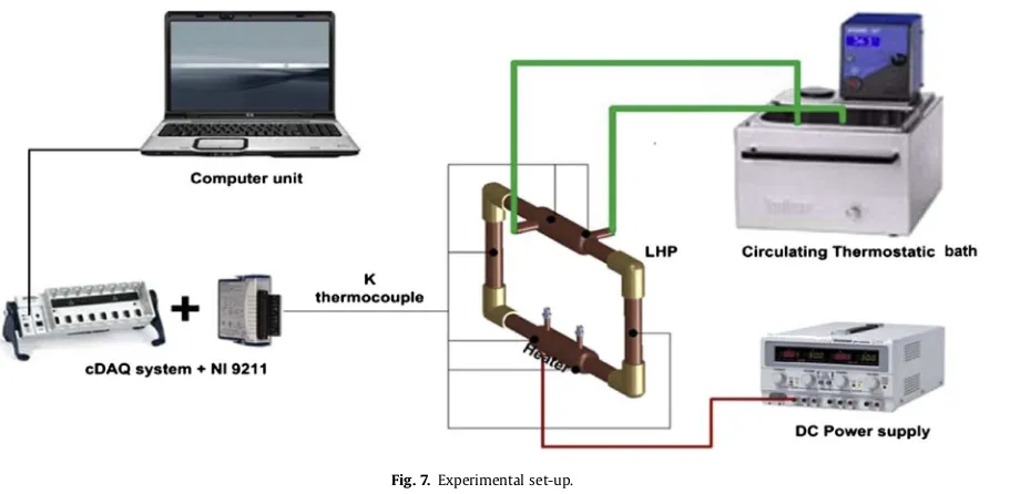
The experimental set-up for the liquid cooled LHP is shown in Fig. 7. The objective was to determine the thermal resistance of LHP as well as the temperature distribution along the LHP for differing heat loads, workingfluids and wick materials. To reproduce elec-tronic thermal activity, the evaporator heating source was powered by electric heaters controlled by an adjustable DC power supply, while heat removal was brought about by circulation of the cooling water through a coaxial liquid cooling heat exchanger. A recircu-lating thermostatic bath was used to provide a continuousflow of cooling water in the heat exchanger; the coolant tank’s tempera-ture stability was controlled with an accuracy rate of0.5C and was set at 25C. The temperature distribution along the LHP was monitored by six K-type thermocouples with an accuracy rate of 0.1C. All the measured temperatures were transmitted to the computer through a Data Acquisition System (NI) in real time and were recorded once every second for further analysis. The entire LHP remained thermally insulated for the duration of the tests. Water and nanofluid were used as the workingfluids.
The position of the thermocouples for every experiment can be seen in Fig. 6. The distance of each point from the origin was 40 mm, 80 mm, 210 mm, 310 mm, 430 mm and 530 mm. From the measurement of temperature distribution of LHP, the sum of the thermal resistances (R) between the evaporator and the condenser section are calculated and defined as
R¼ ðTe TcÞ
Q (3)
whereTe and Tc are the evaporator temperature and condenser temperature respectively [27].Te is calculated from the average value ofT1 andT2, whileTcis calculated from the average value of T4 and T5. The heating power input Q can be calculated by measuring the input electric power given by
Q ¼ V$I (4)
whereVandIare the supplied voltage (in V) and the electric cur-rent (in A) respectively.
Fig. 7.Experimental set-up.
4. Result and discussion
4.1. The influence of wick type and workingfluids on heat pipe performance
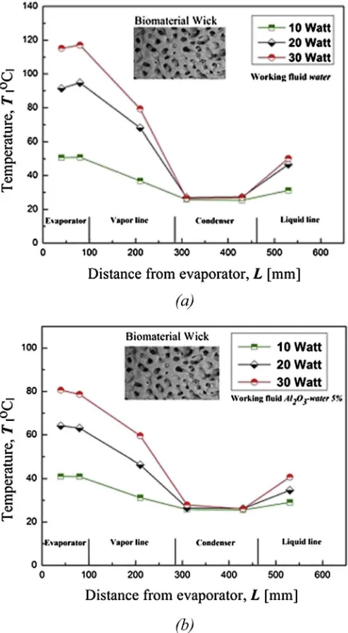
Fig. 8 shows the temperature distribution of LHP with a biomaterial wick and the variation of heat load on the evaporator. All cases showed a decrease in temperature from the evaporator section to the condenser section. The generated heat at the evap-orator section can be better absorbed using a biomaterial wick LHP charged with nanofluid Al2O3ewater at 5% volume fraction. The temperature at the evaporator section using nanofluid 5% vol. fraction decreases approximately 8C, 25C, and 35C more than the temperature decrease using only water for input power 10 W, 20 W and 30 W, respectively. The trend of temperature distribution using a sintered powder wick in the LHP was the same as that of the biomaterial wick. The temperature at the evaporator section also increased with power enhancement.
Fig. 9shows the temperature distribution of the sintered wick and the biomaterial wick LHP charged with water and Al2O3ewater nanofluids as the workingfluids. As seen in thefigure, the tem-perature range on the evaporator section was approximately 41e 51C when the biomaterial wick is applied in LHP. If the sintered wick is used, then the temperature range at the evaporator is be-tween 46C and 60C. This indicated that the use of a biomaterial can reduce temperature on the evaporator. One possible explana-tion for this is that the biomaterial wick, with its pore structure, can provide more capillary force to circulate the workingfluid.
The nanofluid with a 5% volume fraction could absorb more heat in the evaporator LHP than distilled water. The presence of nano-particles on the base fluids increases fluid momentum, and the interfacial contact area of the particles becomes larger, increasing the rate of heat transfer[22].
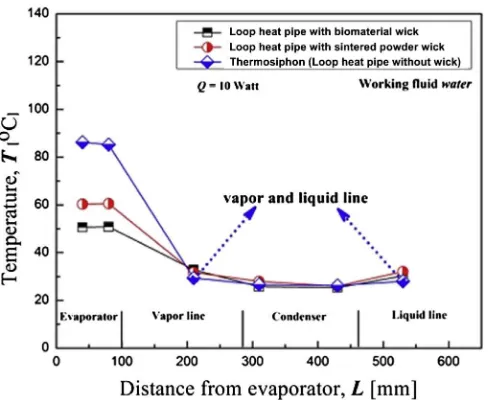
The comparison of LHPs with a sintered powder copper wick, a biomaterial wick and without a wick or thermosyphons is depicted
Fig. 8.Temperature distribution of biomaterial wick LHP (a) with water as working fluid, (b) nanofluids Al2O3ewater 5%.
Fig. 9.Temperature distribution of workingfluids water and nanofluids with (a) biomaterial wick and (b) sintered powder wick LHP.
inFig. 10. It can be seen that the temperature at the evaporator of the LHP with a biomaterial wick was the lowest. The highest temperature was in the LHP without a wick. The low temperature of the biomaterial wick condition occurs because the pore size dis-tribution of biomaterial is more homogeneous and smaller than that of the sintered powder. The better performance of the LHP with wick biomaterials is also due to the better capillarity and permeability of biomaterials. For an LHP without a wick or ther-mosyphons with the absence of a capillary pump in the condensate line, the condensate that flows from the condenser to the
evaporator will be inhibited by steamflowing from the evaporator to the condenser. Steam willflow not only in vapor line but also in liquid line. This condition leads to the dry-out of evaporator near the heated surface. The consequent reduction in temperature dif-ference and the rise in the temperature of the evaporator make the thermal resistance to increase.
Fig. 11andTable 2show the thermal resistance of an LHP of the evaporator and the adiabatic section. A heat pipe charged with Al2O3ewater nanofluid gave lower thermal resistance than that of water as a workingfluid for the same load level. These results were similar to those of Kang et al.[23,24], Liu et al.[25,26], and Do et al. [13]. The lowest thermal resistance of an LHP was produced by a biomaterial wick and Al2O3ewater workingfluid. A comparison of thermal resistance between the LHPs with a biomaterial wick, a sintered powder and no wick shows that the use of biomaterials had the smallest value of thermal resistance. The application of the biomaterial Tabulate as a wick can decrease the thermal resistance by approximately 56.3% more than a sintered powder wick.
4.2. Wick condition after using nanofluids
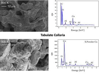
To examine the condition of the various types of wicks after charging Al2O3ewater nanofluids, the wicks were observed with SEM and energy dispersive X-ray analysis (EDAX). The condition of the wicks before and after the use of Al2O3ewater nanofluids is shown inFigs. 12and13. The EDS test inFig. 12shows the condition of the pore structure of biomaterials and sintered powder before the experiments. The majority of the biomaterial wick structure consists of the elements C (1.33%), O (69.51%) and Ca (29.26%), Fig. 10. Distribution temperature of LHPs with sintered powder wick, biomaterial wick
and without wick.
Fig. 11. Thermal resistance of LHPs with biomaterial and sintered powder wick.
Table 2
Thermal resistance of LHP with biomaterial, sintered powder wick and without wick.
Wick material Biomaterial
(tabulate)
S. Powder Cu Without wick
Thermal Resistance (Re-a)C/W
0.68 1.47 3.20
Fig. 12.Wick condition before experiment.
while the wick sintered powder consists of the elements O (0.70%), Si (0.05%) and Cu (99.25%). After the LHP is charged with Al2O3e water nanofluid, the condition of each wick can be analyzed by the thin layer of Al coating on the surface of biomaterials and the wick sintered powder. This is shown in the SEM photograph and EDS test inFig. 13. The amount of Al was 11.38% and 13.43% on the bioma-terial wick and the sintered powder wick, respectively.
5. Conclusion
An extensive experimental study was performed to investigate the influence of a variety of parameters and configurations of LHPs. The performance of the LHP was improved by using a biomaterial as wick: the total heat resistance of the heat pipe was lowest when using a biomaterial wick. The application of the biomaterial Tabu-late wick can decrease the thermal resistance by 56.3% when compared to a sintered powder wick. The use of nanofluids for any concentrations showed better thermal performance than the use of distilled water. The lowest thermal resistance of LHP was produced by a biomaterial wick with Al2O3ewater as the workingfluid.
Acknowledgments
The authors would like to thank Directorate of Higher Education Minister of National Education Republic of Indonesia and the DRPM University of Indonesia for funding this research.
References
[1] Yu.F. Maydanik, Loop heat pipes, Appl. Therm. Eng. 25 (2005) 635e657. [2] Yu.F. Maydanik, S.V. Vershinin, M.A. Korukov, J.M. Ochterbeck, Miniature loop
heat pipesea promising means for cooling electronics, IEEE Trans. Compon. Packag. Technol. 28 (2005) 290e296.
[3] V.G. Pastukhov, Yu.F. Maydanik, C.V. Vershinin, M.A. Korukov, Miniature loop heat pipes for electronics cooling, Appl. Therm. Eng. 23 (2003) 1125e1135. [4] L. Vasiliev, D. Lossouarn, C. Romestant, A. Alexandre, Y. Bertin, Y. Piatsiushyk,
V. Romanenkov, Loop heat pipe for cooling of high-power electronic com-ponents, Int. J. Heat Mass Transf. 52 (2009) 301e308.
[5] V.M. Kiseev, V.V. Vlassov, I. Muraoka, Experimental optimization of capillary structures for loop heat pipes and heat switches, Appl. Therm. Eng. 30 (2010) 1312e1319.
[6] J. Li, D. Wang, G.P. Peterson, Experimental studies on a high performance compact loop heat pipe with a squareflat evaporator, Appl. Therm. Eng. 30 (2010) 741e752.
[7] R.R. Riehl, T. Dutra, Development of an experimental loop heat pipe for application in future space missions, Appl. Therm. Eng. 25 (2005) 101e112. [8] R. Kempers, A.J. Robinson, D. Ewing, C.Y. Ching, Characterization of evaporator
and condenser thermal resistances of a screen mesh wicked heat pipe, Int. J. Heat Mass Transf. 51 (2008) 6039e6046.
[9] R. Kempers, D. Ewing, C.Y. Ching, Effect of number of mesh layers andfluid loading on the performance of screen mesh wicked heat pipes, Appl. Therm. Eng. 26 (2006) 589e595.
[10] N. Putra, W.N. Septiadi, H. Rahman, R. Irwansyah, Experimental study of screen mesh and sintering powder wick on heat pipe performance, Exp. Therm. Fluid Sci. 40 (2012) 10e17.
[11] F. Lefèvre, J.B. Conrardy, M. Raynaud, J. Bonjour, Experimental investigations offlat plate heat pipes with screen meshes or grooves covered with screen meshes as capillary structure, Appl. Therm. Eng. 37 (2012) 95e102. [12] Y.W. Chang, C.H. Cheng, J.C. Wang, S.L. Chen, Heat pipe for cooling of
elec-tronic equipment, Energy Convers. Manage. 49 (2008) 3398e3404. [13] K.H. Do, H.J. Ha, S.P. Jang, Thermal resistance of screen mesh wick heat pipes
using the water-based Al2O3nanofluids, Int. J. Heat Mass Transf. 53 (2010) 5888e5894.
[14] N. Putra, Saputra, M.I. Bimo, R. Irwansyah, W.N. Septiadi, Experimental study on sintered powder wick loop heat pipe, in: The 4th International Meeting of Advances in Thermofluids, Melaka, Malaysia, 3rde4th October, 2011. [15] J. Li, Y. Zou, L. Cheng, Experimental study on capillary pumping performance
of porous wicks for loop heat pipe, Exp. Therm. Fluid Sci. 34 (2010) 1403e 1408.
[16] K.C. Leong, C.Y. Liu, Characterization of sintered copper wicks used in heat pipes, J. Porous Mater. 4 (1997) 303e308.
[17] D.K. Mishra, T.T. Saravanan, G.P. Khanra, S. Girikumar, S.C. Sharma, K. Sreekumar, P.P. Sinha, Studies on the processing of nickel base porous wicks for capillary pumped loop for thermal management of spacecrafts, Adv. Powder Technol. 21 (2010) 658e662.
[18] K.J. Zan, C.J. Zan, Y.M. Chen, S.J. Wu, Analysis of the parameters of the sintered loop heat pipe, Heat Transf. Asian Res. 33 (2004) 515e526.
[19] Y. Tang, D. Deng, L. Lu, M. Pan, Q. Wang, Experimental investigation on capillary force of composite wick structure by IR thermal imaging camera, Exp. Therm. Fluid Sci. 34 (2010) 190e196.
[20] M.K. Russel, C. Young, J.S. Cotton, C.Y. Ching, The effect of orientation of U-shaped grooved and sintered wick heat pipes, Appl. Therm. Eng. 31 (2011) 69e76. [21] F.C. Lin, B.H. Liu, C.T. Huang, Y.M. Chen, Evaporative heat transfer model of a
loop heat pipe with bidisperse wick structure, Int. J. Heat Mass Transf. 54 (2011) 4621e4629.
Fig. 13.Wick condition after experiment.
[22] C.Y. Tsai, H.T. Chien, P.P. Ding, B. Chan, T.Y. Luh, P.H. Chen, Effect of structural character of gold nanoparticles in nanofluid on heat pipe thermal perfor-mance, Mater. Lett. 58 (2004) 1461e1465.
[23] S.W. Kang, W.C. Wei, S.H. Tsai, C.C. Huang, Experimental investigation of nanofluids on sintered heat pipe thermal performance, Appl. Therm. Eng. 29 (2009) 973e979.
[24] S.W. Kang, W.C. Wei, S.H. Tsai, S.Y. Yang, Experimental investigation of silver nano-fluid on heat pipe thermal performance, Appl. Therm. Eng. 26 (2006) 2377e2382.
[25] Z.H. Liu, Y.Y. Li, R. Bao, Thermal performance of inclined grooved heat pipes using nanofluids, Int. J. Therm. Sci. 49 (2010) 1680e1687.
[26] Z.H. Liu, Q.Z. Zhu, Application of aqueous nanofluids in a horizontal mesh heat pipe, Energy Convers. Manage. 52 (2011) 292e300.
[27] Yu.F. Maydanik, S. Vershinin, M. Chernysheva, S. Yushakova, Investigation of a compact copperewater loop heap pipe with aflat evaporator, Appl. Therm. Eng. 31 (2011) 3533e3541.