TE
AM
Java Enterprise
Design Patterns
MARK GRAND
John Wiley & Sons, Inc.
New York ● Chichester ● Weinheim ● Brisbane ● Singapore ● Toronto
Java
™
Enterprise
Design Patterns
Patterns in Java
TM, Volume 3
MARK GRAND
John Wiley & Sons, Inc.
Developmental Editor: Kathryn A. Malm Managing Editor: Angela Smith
New Media Editor: Brian Snapp Text Design & Composition:
Designations used by companies to distinguish their products are often claimed as trademarks. In all instances where John Wiley & Sons, Inc., is aware of a claim, the product names appear in initial capital or ALL CAPITAL LETTERS. Readers, how-ever, should contact the appropriate companies for more complete information regarding trademarks and registration.
This book is printed on acid-free paper. ●∞
Copyright © 2002 by Mark Grand. All rights reserved. Published by John Wiley & Sons, Inc., New York Published simultaneously in Canada.
No part of this publication may be reproduced, stored in a retrieval system or transmitted in any form or by any means, electronic, mechanical, photocopying, recording, scanning or otherwise, except as permitted under Sections 107 or 108 of the 1976 United States Copyright Act, without either the prior written permission of the Publisher, or authorization through payment of the appropriate per-copy fee to the Copyright Clearance Center, 222 Rosewood Drive, Danvers, MA 01923, (978) 750-8400, fax (978) 750-4744. Requests to the Publisher for permission should be addressed to the Permissions Department, John Wiley & Sons, Inc., 605 Third Avenue, New York, NY 10158-0012, (212) 850-6011, fax (212) 850-6008, E-Mail: PERMREQ @ WILEY.COM.
This publication is designed to provide accurate and authoritative information in regard to the subject matter covered. It is sold with the understanding that the publisher is not engaged in professional services. If professional advice or other expert assistance is required, the services of a competent professional person should be sought.
Library of Congress Cataloging-in-Publication Data: Grand, Mark.
Java Enterprise design patterns / Mark Grand. p. cm.
ISBN 0-471-33315-8 (pbk.: alk. paper)
1. Java (Computer program language) 2. Web servers. 3. Object-oriented programming (Computer science) I. Title.
QA76.73.J38 G72 2001
005. 13'3—dc21 2001045611
Acknowledgments vii
About the Author viii
Chapter 1 Introduction to Software Patterns 1
Description of Patterns 2
Pattern Name 3
Synopsis 3 Context 3 Forces 3 Solution 4 Consequences 4 Implementation 4
Known Uses 4
Code Example 4
Related Patterns 4
Chapter 2 Overview of UML 7
Class Diagram 8
Collaboration Diagram 18
Statechart Diagram 26
Deployment Diagram 28
Chapter 3 The Software Life Cycle 29
Chapter 4 Transaction Patterns 33
Acid Transaction 37
Composite Transaction 55
Two Phase Commit 65
Audit Trail 75
Chapter 5 Distributed Architecture Patterns 81
Shared Object 83
Object Request Broker 89
Object Replication 99
Redundant Independent Objects 109
Prompt Repair 115
Mobile Agent 119
Demilitarized Zone 129
Process Pairs 133
Chapter 6 Distributed Computing Patterns 137
Object Identifier 139
Registry 149
Protection Proxy 157
Publish-Subscribe 175
Retransmission 187
Mailbox 195
Heavyweight/Lightweight 203
Heartbeat 209
Connection Multiplexing 229
Chapter 7 Concurrency Patterns 275
Session Object 277
Lock File 285
Static Locking Order 291 Optimistic Concurrency 297
Thread Pool 303
Chapter 8 Temporal Patterns 347
Time Server 349
Versioned Object 355
Temporal Property 373
Chapter 9 Database Patterns 387
Persistence Layer 389
CRUD 407
Stale Object 413
Type Conversion 423
IsDirty 431
Lazy Retrieval 439
Appendix A Persistence Framework 445
Bibliography 475
This book would not have been possible without the inspiration, encour-agement and assistance of others.
I want to thank Brad Appleton for his diligent reviews and concern with form.
Wolfgang W. Keller provided extensive feedback on the transaction patterns chapter.
Frank Sauer provided excellent feedback on the database patterns chapter.
I also want to thank the members of the pattern discussion group at University of Illinois, Champaign-Urbana, for their invaluable comments on my manuscript: Joe Yoder, Brian Foote, Hiroaki Nakamura, Roger Whitney, Ralph Johnson, Brian Marick, Wanghong Yuan, Paul Rubel, Frederico Balaguer, Alejandra Garrido, Don Roberts, Zhijiang “John” Han, Weerasak Witthawuskul, Peter Hatch, Dragos Malolescu, and Les Tyrrell.
A
B
O
U
T
T
H
E
A
U
T
H
O
R
Mark Grandis a consultant specializing in distributed systems, object-oriented design, and Java. He is currently working on an open source framework for gluing components and programs into an application. Mark Grand is the author of a series of books titled Patterns in Java. He is a consultant who specializes in Distributed Systems, Object Oriented Design, and Java. He was the architect of the first commercial B2B e-commerce product for the Internet.
TE
AM
C
H
A
P
T
E
R
Introduction
to Software Patterns
1
Software patternsare reusable solutions to recurring problems that occur during software development. For purposes in this book, we refer to soft-ware patterns simply as patterns.
What makes a bright, experienced programmer so much more produc-tive than a bright but inexperienced programmer? Experience. Experience gives programmers wisdom. As programmers gain experience, they recog-nize the similarity between new problems and those problems that they have solved before. With even more experience, they recognize that the solutions for similar problems follow recurring patterns. Experienced programmers recognize the situations where these patterns apply and quickly draw on existing solutions without having to stop, analyze the problems, and then pose possible strategies.
When a programmer discovers a pattern, it’s just an insight. In most cases, to go from a nonverbalized insight to a well-thought-out idea that the programmer can clearly articulate is surprisingly difficult. It’s also an extremely valuable step. When we understand a pattern well enough to put it into words, we are able to intelligently combine it with other patterns. More important, once put into words, a pattern can be used in discussions among programmers who know the pattern. That allows programmers to more effectively collaborate and combine their wisdom. It can also help to
avoid the situation where programmers argue over various solutions to a problem only to find out later that they were really thinking of the same solution but expressing it in different ways.
Putting a pattern into words has an additional benefit for less experi-enced programmers who have not yet discovered the pattern. Once a pat-tern has been put into words, more experienced programmers can teach it to programmers who are new to the pattern.
This book provides experienced programmers with a common vocab-ulary to discuss patterns. It also allows programmers who have not yet dis-covered a pattern to learn about the pattern.
Though this book includes a substantial breadth of patterns, addi-tional patterns did not make it into this book. You, dear reader, may dis-cover some of these patterns for yourself. Some patterns you disdis-cover may be highly specialized and of interest to only a small number of people. Other patterns may be of very broad interest and worthy of inclusion in a future volume of this book. If you wish to communicate such a pattern to me, my e-mail is [email protected].
The patterns cataloged in this book convey constructive ways of orga-nizing parts of the software development cycle. Other patterns that recur in programs are not constructive. These types of patterns are called
AntiPatterns.Because AntiPatterns can cancel out the benefits of patterns, this book does not attempt to catalog them.
Description of Patterns
Patterns are usually described using a format that includes the following information:
•
A description of the problem that includes a concrete example and a solution specific to the concrete problem•
A summary of the forces that lead to the formulation of a general solution•
A general solution•
The consequences, good and bad, of using the given solution to solve a problem•
A list of related patternsPattern Name
The Pattern Name section consists of the name of the pattern and a bibliogra-phy reference that indicates where the pattern originated. Most patterns don’t have any additional text under this heading. For those that do, this section contains information about the derivation or general nature of the pattern.
The bibliography reference indicates where the ideas in the pattern were first written in the form of a pattern. Because patterns are based on established practices, in many cases there are other sources of the ideas in the pattern other than the bibliography reference. Usually, the author of a pattern is not the first person to discover the ideas that underlie the pat-tern. In particular, I do not claim to be the first person to discover the ideas presented in this book. Those patterns with a bibliographic reference to this book merely indicate that I know of no other place where that par-ticular set of ideas has been documented as a pattern. The bibliography entry next to a pattern name is provided to help you trace the development of the pattern itself, not the underlying ideas.
Synopsis
The Synopsis section provides a brief summary of the pattern—both the essence of the problem that the pattern aims to solve and the solution vided by the pattern. The synopsis is primarily directed at experienced pro-grammers who may recognize the pattern as one they already know, but may not have had a name for. After recognizing the pattern from its name and synopsis, it may be sufficient to skim over the rest of the pattern description.
Don’t be discouraged if you don’t recognize a pattern from its name and synopsis. Instead, read carefully through the rest of the pattern description to better understand it.
Context
The Context section describes the problem that the pattern addresses. For most patterns, the problem is introduced in terms of a concrete example. After presenting the problem in the example, the Context section suggests a design solution for that problem.
Forces
solution. The reasons for not using a solution are as important as the rea-sons for using a solution. Both are organized as bulleted points as follows:
⁄ Reasons to use a solution are bulleted with a happy face.
Ÿ Reasons not to use a solution are bulleted with a sad face.
Solution
The Solution section is the core of the pattern. It describes a general-purpose solution to the problem that the pattern addresses.
Consequences
The Consequences section explains the implications—good, bad, and neu-tral—for using the solution. Most consequences are organized into bul-leted points like this:
⁄ Good consequences are bulleted with a happy face.
•
Neutral consequences are bulleted with a dot.Ÿ Bad consequences are bulleted with a sad face.
Implementation
The Implementation section describes the important considerations to be aware of when executing the solution. It may also describe some common variations or simplifications of the solution. Some patterns may not have an Implementation section because these concerns are not relevant.
Known Uses
The Known Uses section highlights some well-known uses for the pattern.
Code Example
The Code Example section contains a code example showing a sample implementation for a design that uses the pattern. For some patterns, such as Graphical User Interface (GUI) design patterns, a code example is not relevant.
Related Patterns
A Very Brief History of Patterns
The idea of software patterns originally came from the field of architec-ture. An architect named Christopher Alexander wrote some revolutionary books that describe patterns in building architecture and urban planning:
•
A Pattern Language: Towns, Buildings, Construction(Oxford University Press, 1977)•
The Timeless Way of Building(Oxford University Press, 1979)The ideas presented in these books are applicable to a number of fields outside of architecture, including software.
In 1987, Ward Cunningham and Kent Beck used some of Alexander’s ideas to develop five patterns for user-interface design. They published a paper on the UI patterns at OOPSLA-87: Using Pattern Languages for Object-Oriented Programs.
In the early 1990s, four authors—Erich Gamma, Richard Helm, John Vlissides, and Ralph Johnson—began work on one of the most influential computer books of this decade: Design Patterns.Published in 1994, the book popularized the idea of patterns. Design Patternsis often called the Gang of Four, or GoF, book.
This book you are reading represents an evolution of patterns and objects since the GoF book was published. The GoF book used C++and
SmallTalk for its examples. I use Java and take a rather Java-centric view of most things. When the GoF book was written, the Unified Modeling Language (UML) did not exist. It’s now widely accepted as the preferred notation for object-oriented analysis and design. Therefore, that is the notation I use in this book.
Organization of This Book
This book follows my previous two works on Patterns in Java.The first vol-ume focused exclusively on general-purpose design patterns. The second volume moved away from design patterns to include a variety of patterns used to assign responsibilities to classes, design GUIs, write code, and test software.
This third volume contains design and architectural patterns for use in distributed and enterprise applications. The topics include patterns related to transaction design, distributed computing, concurrency, time, and using databases with object-oriented programs.
3, containing an overview of the software life cycle, provides the context in which the patterns are used. Chapter 3 also offers a case study that includes examples for using the patterns. The remaining chapters describe different types of patterns.
The CD-ROM that accompanies this book contains all of the code examples. In some cases, the examples on the CD-ROM are more complete than those that appear in this book. The CD-ROM also contains trial ver-sions of software related to the patterns.
C
H
A
P
T
E
R
Overview of UML
7
The Unified Modeling Language (UML) is a notation that you can use for object-oriented analysis and design. This chapter contains a brief introduc-tion to the UML and to the subset and extensions of the UML that are used in this book. For a complete description of the UML, see www.omg.org.
Books on UML define the pieces of information stored in instances of a class as attributes;they define a class’s encapsulations of behavior as oper-ations.Those terms, like UML, are not specific to any implementation lan-guage. However, this book is not language neutral. It assumes that you are using Java as your implementation language. This book also uses mostly Java-specific terms rather than terms that are language neutral but less familiar to Java programmers. For example, I use the words attributeand
variableinterchangeably, preferring the Java-specific term, variable.I use the words operationandmethodinterchangeably, preferring the Java-specific term, method.
UML defines a number of different kinds of diagrams. The rest of this chapter is organized into sections that describe each of those diagrams and the elements that appear in them.
If you are experienced with object-oriented design, you will find most of the concepts that underlie the UML notation to be familiar. If you find many of the concepts unfamiliar, read only as much of this chapter as you
feel comfortable with. In later chapters, if a UML diagram contains some-thing you want explained, return to Chapter 2 and find a diagram that con-tains a similar UML element.
Class Diagram
Aclass diagramis a diagram that shows classes, interfaces, and their relationships. The most basic element of a class diagram is a class. Figure 2.1 shows many of the features that a class can have within a class diagram.
Classes are drawn as rectangles. The rectangles can be divided into two or three compartments. The class rectangle shown in Figure 2.1 has three compartments. The top compartment contains the name of the class. The middle compartment lists the class’s variables. The bottom compart-ment lists the class’s methods.
The symbols that precede each variable and method are visibility indi-cators.The possible visibility indicators and their meanings are as follows:
+Public #Protected
-Private
The variables in the middle compartment are shown as follows:
visibilityIndicator name : type
Therefore, the two variables shown in the class in Figure 2.1 are pri-vate variables. The name of the first variable is instanceand its type is AudioClipManager. The name of the second variable is prevClipand its type is AudioClip.
AudioClipManager
-instance:AudioClipManager -prevClip:Audioclip
«constructor» -AudioClipManager( ) «misc»
+getInstance( ):AudioClipManager +play(:AudioClip)
+loop(:AudioClip) +stop( ) ...
Though not shown in Figure 2.1, an initial value can be indicated for a variable by following the variable’s type with an equal sign followed by the value like this:
ShutDown:boolean = false
You will notice that the first variable shown in the class is underlined. If a variable is underlined, that means it is a static variable. This applies to methods, too. Underlined methods are static methods.
The methods in the bottom compartment are shown as follows:
visibilityIndicator name ( formalParameters ) : returnType
ThegetInstancemethod shown in the class in Figure 2.1 returns an
AudioClipManagerobject.
The UML indicates a void method by leaving out the ": returnType"
from a method to indicate that it does not return anything. Therefore, the
stopmethod shown in the class in Figure 2.1 does not return any result. A method’s formal parameters consists of a name and type like this:
setLength(length:int)
If a method has multiple parameters, commas separate them:
setPosition(x:int, y:int)
Two of the methods in the class shown in Figure 2.1 are preceded by a word in guillemets:
<<constructor>>
In UML, drawing a word in guillemets is called a stereotype.A stereo-type is used like an adjective to modify what comes after it. The con-structorstereotype indicates that the methods that follow it are constructors. The miscstereotype indicates that the methods that come after it are regular methods. Additional uses for stereotypes are described later in this chapter.
One last element that appears in the class shown in Figure 2.1 is an ellipsis ( . . . ). If an ellipsis appears in the bottom compartment of a class, it means that the class has additional methods not shown in the diagram. If an ellipsis appears in the middle compartment of a class, the class has additional variables not shown in the diagram.
Often, it is not necessary or helpful to show as many details of a class as are shown in Figure 2.1. Figure 2.2 shows a class that is drawn with only two compartments:
compart-10
■ CHAPTER TWOAudioClipManager
«constructor» -AudioClipManager( ) «misc»
+getInstance( ):AudioClipManager +play(:AudioClip)
+loop(:AudioClip) +stop( ) ...
FIGURE 2.2 A two-compartment class.
AudioClipManager
instance:AudioClipManager prevClip:Audioclip
‹‹constructor›› AudioClipManager ‹‹misc››
getInstance play loop stop ...
FIGURE 2.3 Simplified class.
ment shows its methods. If a class is drawn with only two compartments, it simply means that its variables are not shown. It does not mean that it has no variables.
The visibility indicators may be omitted from methods and variables. When a method or variable is shown without a visibility indicator, that means only that there is no indication of the method’s or variable’s visibil-ity. It does not imply that the methods or variables are public, protected, or private.
A method’s parameters may be omitted if their return values are also omitted. For example, the visibility indicators and method parameters are omitted from the class shown in Figure 2.3.
The simplest form of a class contains only one compartment with the class name, as shown in Figure 2.4.
A one-compartment representation of a class merely identifies the class. It provides no indication about what variables or methods the class has.
Interfaces are drawn in a manner similar to classes. The difference is that the name in the top compartment is preceded by an interface
stereotype. Figure 2.5 is an example of an interface.
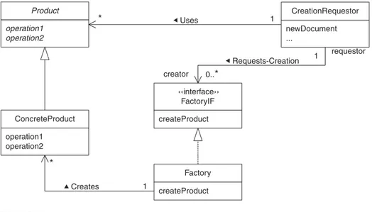
Classes and interfaces are important elements of class diagrams. The other elements of a class diagram show the relationships between classes and interfaces. Figure 2.6 is a typical class diagram.
The lines in Figure 2.6 indicate the relationship between the classes and interface. A solid line with a closed, hollow head such as the one in
TE
AM
Figure 2.7 indicates the relationship of a subclass that inherits from a superclass.
The class diagram in Figure 2.6 shows the abstract class Productas the superclass of the ConcreteProductclass. You can tell that it is abstract because its name is italicized. You can tell that its methods are abstract because they are also italicized.
A similar sort of line is used to indicate that a class implements an interface. It is a dotted or dashed line with a closed head, as shown in Figure 2.8.
The class diagram in Figure 2.6 shows that the Factoryclass imple-ments the FactoryIFinterface.
The other lines show the other types of relationships between the classes and interface. UML calls these other types of relationships associa-tions.A number of things can appear with associations to provide informa-tion about the nature of an associainforma-tion. The following items are opinforma-tional, but this book consistently uses them wherever it makes sense.
Association name. Somewhere around the middle of an associa-tion there may be an association name.The name of an associa-tion is always capitalized. There may be a triangle at one end of the association name. The triangle indicates the direction in which you should read the association.
Looking at Figure 2.6, you will see that the association between the FactoryandConcreteProductclasses has the nameCreates.
Navigation arrows. Arrowheads that may appear at the ends of an association are called navigation arrows.Navigation arrows indi-cate the direction in which you may navigate an association.
AudioClipManager
FIGURE 2.4 A one-compartment class.
‹‹interface›› AddressIF
getAddress1 setAddress1 getAddress2 setAddress2 getCity setCity getState setState getPostalCode setPostalCode
Looking at the association named Createsin Figure 2.6, you will see that it has a navigation arrow pointing from the
Factoryclass to the ConcreteProductclass. Because of the nature of creation, it seems clear that this means the
Factoryclass is responsible for creating instances of the
ConcreteProductclass.
The nature of some associations is less obvious. To make the nature of such associations clear, it may be necessary to sup-ply additional information about the association. One common way to clarify the nature of an association is to name the role that each class plays in the association.
Role name. To clarify the nature of an association, the name of the role that each class plays in the association can appear at each end of an association next to the corresponding class. Role names are always lowercase. That makes them easier to distin-guish from association names, which are always capitalized.
In Figure 2.6, the CreationRequestorclass and the
FactoryIFinterface participate in an association named
Requests-Creation. The CreationRequestorclass partici-pates in that association in a role called requestor. The
FactoryIFinterface participates in that association in a role calledcreator.
Product
operation1 operation2
ConcreteProduct
operation1 operation2
CreationRequestor
newDocument ...
Uses
* 1
‹‹interface›› FactoryIF
createProduct
Requests-Creation 1
requestor
creator
Factory
createProduct Creates
*
1
0..*
FIGURE 2.6 Class diagram.
Multiplicity indicator. Another detail of an association that is usu-ally supplied is how many instances of each class participate in an occurrence of an association. A multiplicity indicator may appear at each end of an association to provide that informa-tion. A multiplicity indicator can be a simple number like 0 or 1. It can be a range of numbers indicated like this:
0..2
An asterisk as the high value of a range means an unlim-ited number of occurrences. The multiplicity indicator 1..*
means at least one instance; 0..*means any number of instances. A simple *is equivalent to 0..*.
Looking at the multiplicity indicators in Figure 2.6, you will see that each one of the associations in the drawing is a one-to-many relationship.
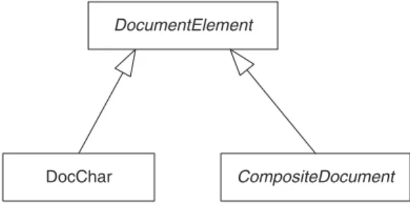
Figure 2.9 is a class diagram that shows a class with multi-ple subclasses.
Although the drawing in Figure 2.9 is perfectly valid, the UML allows a more aesthetically pleasing way to draw a class with multiple subclasses. You can combine the arrowheads as shown in Figure 2.10. The diagram in Figure 2.10 is identical in meaning to the diagram in Figure 2.9.
Sometimes there is a need to convey more structure than is implied by a simple one-to-many relationship. The type of one-to-many relation-ship where one object contains a collection of other objects is called an
aggregation.A hollow diamond at the end of the association indicates aggregation. The hollow diamond appears at the end of the association attached to the class that contains instances of the other class. The class diagram in Figure 2.11 shows an aggregation.
FIGURE 2.8 Implements an interface.
DocChar CompositeDocument DocumentElement
The class diagram in Figure 2.11 shows a class named MessageMan-ager. Each of its instances contains zero or more instances of a class namedMIMEMsg.
UML has another notation to indicate a stronger relationship than aggregation. That relationship is called composite aggregation.For an aggregation to be composite, two conditions must be satisfied:
•
Aggregated instances must belong to only one composite at a time.•
Some operations must propagate from the composite to itsaggre-gated instances. For example, when a composite object is cloned, its clone method will typically clone the aggregated instances so that the cloned composite will own clones of the original aggregated instances.
Figure 2.12 is a class diagram that contains a composite aggregation. The class diagram in Figure 2.12 shows a Documentclass.Document
objects can contain Paragraphobjects.Paragraphobjects can contain
DocCharobjects. Because of the composite aggregation, you know that
Paragraphobjects do not share DocCharobjects and Documentobjects do not share Paragraphobjects.
Some associations are indirect. Instead of classes directly associ-ated with each other, they are associassoci-ated indirectly through a third class. Consider the class diagram in Figure 2.13. The association in Figure 2.13 shows that instances of the Cacheclass refer to instances of the Object
class through an instance of the OjbectIDclass.
There is another use for ellipsis in a class diagram. Some class dia-grams need to show that a class has a large or open-ended set of subclasses
DocChar CompositeDocument
DocumentElement
FIGURE 2.10 Single inheritance arrow.
MessageManager Manages
0..* MIMEMsg
▲
while showing only a few subclasses as examples. The class diagram in Figure 2.14 shows how ellipsis can be used to show just that.
The class diagram in Figure 2.14 shows a class named DataQuery
that has subclasses named JDBCQuery,OracleQuery,SybaseQuery, and an indefinite number of other classes that are indicated by the ellipsis.
An association between classes or interfaces implies a dependency that involves an object reference that connects two objects. Other types of depen-dencies are possible. A dashed line is used to indicate a dependency in the more general sense. Figure 2.15 shows an example of such a dependency.
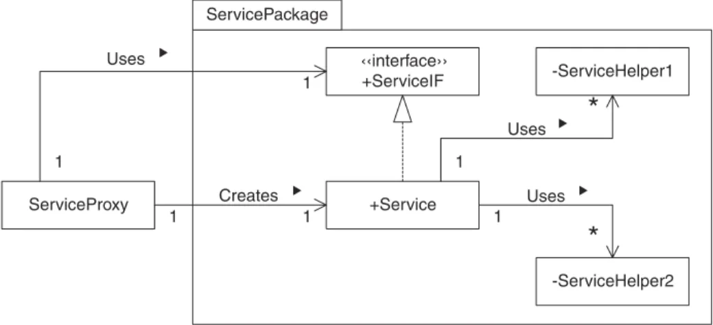
The classes in a class diagram can be organized intopackages.
Packages are drawn as a large rectangle with a small rectangle above the large one. The small rectangle contains the name of the package. The small and large rectangles are arranged to have an overall shape similar to a manila folder. The class diagram in Figure 2.16 contains a package namedServicePackage. A visibility indicator can precede the name of classes and interfaces that appear within a package. Public classes are accessible to classes outside of the package; private classes are not.
Document
Paragraph
DocChar 0..* 0..*
FIGURE 2.12 Composite aggregation.
ObjectID
Cache
addObject( Object ) fetchObject( ObjectID )
Object 1
0..* Caches
There may be aspects of a design you cannot make sufficiently clear without adding a comment to a diagram. Comments in the UML are drawn as a rectangle with its upper right corner turned down. Comments are connected to the diagram element to which they relate by a dashed line. The class diagram in Figure 2.17 contains a comment.
Figure 2.17 shows the static class MilestoneMemento, which is a pri-vate member of the GameModelclass. There is no standard way in the UML to represent a static private member class. The diagram uses a stereotype as an extension to the UML to indicate that the MilestoneMementoclass is static. It uses an association to indicate that the MilestoneMementois a private member of the GameModelclass. To make the relationship even more clear, there is a comment about it in Figure 2.17.
Class diagrams can include objects. Most of the objects in the dia-grams in this book are drawn as shown in Figure 2.18.
The object shown in Figure 2.18 is an instance of a class named Area. The underline tells you that it is an object. A name may appear to the left of the colon (:). The only significance of the name is that if you can use it to identify the individual object.
Some diagrams indicate an object as just an empty rectangle with nothing inside it. Obviously, blank objects cannot be used to identify any
BusinessClass1
«interface» BusinessClass1PersisterIF
persists
FIGURE 2.15 Dependency.
DataQuery
...
JDBCQuery OracleQuery SybaseQuery
particular kind of object. However, they can be used in a diagram that shows a structure in which objects of unspecified type are connected. The class diagram in Figure 2.19 shows such a structure.
The lines that connect two objects are not associations. The lines that connect objects are called links.Links are connections between objects, whereas associations are relationships between classes. A link is
+Service -ServiceHelper1 Uses -ServiceHelper2 Uses ‹‹interface›› +ServiceIF ServiceProxy Uses Creates 1 1 1 1 1 1
*
*
ServicePackage ▲ ▲ ▲ ▲FIGURE 2.16 Package.
«interface» Serializable Requests Milestone Memento Creation Notifies of Milestones 1 1 1 1 «static» MilestoneMemento MilestoneMementoManager snapshotMilestone(description:String) getMilestoneMementos( ):MilestoneMementoIF restoreFromMemento(:MilestoneMementoIF) GameModel createMemento(description:String):MilestoneMementolF setMemento(:MilestoneMementoIF) Is a Private Member Class of member class declaring class
MilestoneMemento is a private static class member of the GameModel class.
an occurrence of an association, just as an object is an instance of a class. Links can have association names, navigation arrows, and most of the other embellishments that associations can have. However, since a link is a connection between two objects, links may not have multiplicity indica-tors or aggregation diamonds.
Some diagrams consist only of objects and links. Such diagrams are considered a kind of class diagram. However, there is a special name for that kind of diagram—an object diagram.Figure 2.20 is an example of an object diagram.
Collaboration Diagram
Class and object diagrams show relationships between classes and objects. They also provide information about the interactions that occur between classes. They do not show the sequence in which the interactions occur or any concurrency that they may have.
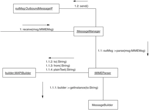
Collaboration diagrams show objects, the links that connect them, and the interactions that occur over each link. They also show the
sequence and concurrency requirements for each interaction. Figure 2.21 is a simple example of a collaboration diagram.
Any number of interactions can be associated with a link. Each inter-action involves a method call. Next to each interinter-action or group of interac-tions is an arrow that points to the object whose method is called by the interaction. The entire set of objects and interactions shown in a collabo-ration diagram is collectively called a collaboration.
:Area
FIGURE 2.18 Object.
Facade
Each of the interactions shown in Figure 2.21 begins with a sequence number and a colon. Sequence numbers indicate the order in which method calls occur. An interaction with the number 1 must come before an interaction with the number 2 and so on.
Multilevel sequence numbers consist of two or more numbers sepa-rated by a period. Notice that most of the sequence numbers in Figure 2.21
:ConcreteComposite1
:ConcreteComponent2 :ConcreteComposite2 :ConcreteComponent1 Contains
Contains
:ConcreteComponent2
:ConcreteComponent1
:ConcreteComponent2 Contains
Contains
Contains Contains
FIGURE 2.20 Object diagram.
:MessageManager 1: receive(msg:MIMEMsg)
:MIMEParser
1.1: outMsg := parse(msg:MIMEMsg)
MessageBuilder 1.1.1: builder := getInstance(to:String)
builder:MAPIBuilder
1.1.2: to(:String) 1.1.3: from(:String) 1.1.4: plainText(:String) outMsg:OutboundMessageIF 1.2: send()
are multilevel sequence numbers. Multilevel sequence numbers corre-spond to multiple levels of method calls. The portion of a multilevel sequence number to the left of its rightmost period is called its prefix.For example, the prefix of 1.3.4 is 1.3.
Interactions numbered with a multilevel sequence number occur dur-ing another interaction’s method call. The other method call is determined by the interaction’s prefix. The method calls of the interactions numbered 1.1 and 1.2 are made during the method call of interaction 1. Similarly, interactions numbered 1.1.1, 1.1.2, 1.1.3, . . . occur during the method call of interaction 1.1.
Among interactions numbered with the same prefix, their methods are called in the order determined by the last number in their sequence numbers. Therefore, the methods of interactions numbered 1.1.1, 1.1.2, 1.1.3, . . . are called in that order.
As mentioned earlier, links represent a connection between two objects. Because of that, links may not have any multiplicity indicators. That works well for links that represent an occurrence of an association between a definite number of objects. Associations that have a star multi-plicity indicator on either end involve an indefinite number of objects. There is no way to draw an indefinite number of links to an indefinite number of objects. UML provides a symbol that allows us to draw links that connect an indefinite number of objects. That symbol is called a mul-tiobject.It represents an indefinite number of objects. It looks like a rect-angle behind a rectrect-angle. The collaboration diagram in Figure 2.22 contains a multiobject.
The collaboration diagram in Figure 2.22 shows an ObservableIF
object calling a Multicasterobject’s notifymethod. The Multicaster
object’s implementation of the notifymethod calls notifymethod of an
indefinite number of ObserverIFobjects linked to the Multicaster
object.
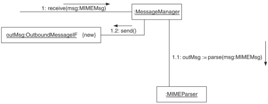
Objects created as a result of a collaboration may be marked with the property{new}. Temporary objects that exist only during a collaboration
may be marked with the property {transient}.* The collaboration dia-gram in Figure 2.23 shows a collaboration that creates an object.
20
■ CHAPTER TWOo:ObservableIF 1: notify(o) :Multicaster 1.1: notify(o) :ObserverIF
FIGURE 2.22 Multiobject.
* The UML and Java use the word transientin very different ways. Java uses transientto mean that a variable is not part of an object’s persistent state. UML uses it to mean that an object has a bounded lifetime.
TE
AM
Some interactions occur concurrently rather than sequentially. A let-ter at the end of a sequence number indicates concurrent inlet-teractions. For example, the methods of interactions numbered 2.2a and 2.2b would be called concurrently and each call would run in a separate thread. Consider the collaboration diagram in Figure 2.24. The top-level interaction is num-bered 1. During that interaction, first interaction 1.1 is invoked. Then interactions 1.2a and 1.2b are simultaneously invoked. After that, interac-tions 1.3 and 1.4 are invoked, in that order.
An asterisk after a sequence number indicates a repeated interaction. Consider the collaboration diagram in Figure 2.25.
The collaboration in Figure 2.25 begins by calling the TollBooth
object’s startmethod. That method repeatedly calls the object’s
collectNextTollmethod. The collectNextTollmethod calls the
:MessageManager 1: receive(msg:MIMEMsg)
:MIMEParser
1.1: outMsg := parse(msg:MIMEMsg) outMsg:OutboundMessageIF {new} 1.2: send()
FIGURE 2.23 New object.
:EMailEncrypter
:Logger
1: encryptMsg(plainText:MimeMsg)
1.1: logMessageReceipt(plainText:MimeMsg) 1.4: logMessageSent(e:'EncryptedMsg)
:MimeParser
1.2a: validateMIMEStructure() :KeyManager
1.2b: getKey(to:String) :EMailSender 1.3: sendMsg(e:encryptedMsg)
TollBasketobject’s collectTollmethod and the TollGateobject’s
raiseGatemethod.
One other thing to notice about the collaboration diagram in Figure 2.25 is the <<self>>stereotype that appears next to the link for interac-tion 1.1. It serves to clarify the fact that the link is a self-reference.
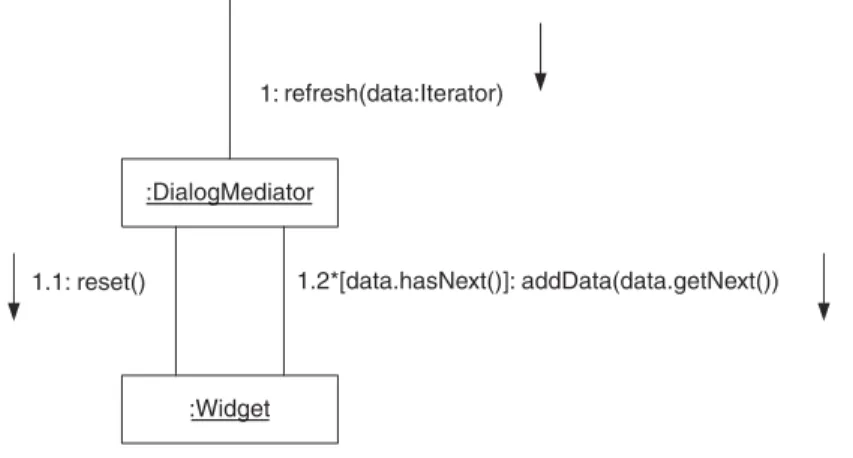
Unlike the example in Figure 2.25, most repetitive interactions occur conditionally. UML allows a condition to be associated with a repetitive interaction by putting it after the asterisk inside of square brackets. The collaboration diagram in Figure 2.26 shows an example of a conditional repetitive interaction.
Figure 2.26 shows an Iteratorobject being passed to a
DialogMediatorobject’s refreshmethod. Its refreshmethod in turn calls a Widgetobject’s resetmethod and then repeatedly calls its addData
method while the Iteratorobject’s hasNextmethod returns true.
1: start() 1.1*: collectNextToll()
:TollBooth ‹‹self››
:TollBasket :TollGate 1.1.1: collectToll() 1.1.2: raiseGate()
FIGURE 2.25 Tollbooth.
:DialogMediator
1: refresh(data:Iterator)
:Widget
1.1: reset() 1.2*[data.hasNext()]: addData(data.getNext())
It is important to note that the UML specification does not define the meaning of conditions associated with repetitive interactions very pre-cisely. In particular, the UML spec says that what appears between the square brackets can “be expressed in pseudocode or an actual program-ming language.” This book consistently uses Java for that purpose.
When dealing with multiple threads, something that often needs to be specified about methods is what happens when two threads try to call the same method at the same time. UML allows that to be specified by placing one of the following constructs after a method:
{concurrency = sequential}. This means that only one thread at
a time should call a method. No guarantee is made about the correctness of the method’s behavior if the method is called by multiple threads at a time.
{concurrency = concurrent}. This means that if multiple
threads call a method at the same time they will all execute it concurrently and correctly.
{concurrency = guarded}. This means that if multiple threads
call a method at the same time, only one thread at a time will be allowed to execute the method. While one thread executes the method, other threads will be forced to wait until it is their turn. This is similar to the behavior of synchronized Java methods.
The collaboration diagram in Figure 2.27 shows an example of a syn-chronized method.
There are refinements to thread synchronization used in this book for which there is no standard representation in UML. This book uses some extensions to the {concurrency=guarded}construct to represent those refinements.
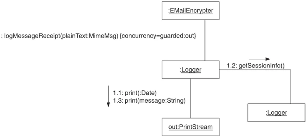
Sometimes the object that the threads need to synchronize on is not the same object whose method is called by an interaction. Consider the collaboration diagram in Figure 2.28.
:EMailEncrypter
:Logger 1: logMessageReceipt(plainText:MimeMsg) {concurrency=guarded}
In Figure 2.28, {concurrency=guarded:out}refers to the object labeledout. Before the method call can actually take place, the thread that controls the call must own the lock associated with the outobject. This is identical to Java’s semantics for a synchronized statement.
Sometimes there are preconditions beyond acquiring ownership of a lock that must be met before a thread may proceed with a method call. Such preconditions are indicated by a vertical bar followed by the precon-dition. The collaboration diagram in Figure 2.29 shows such preconditions followingguardedand a vertical bar.
The collaboration diagram in Figure 2.29 shows two asynchronous interactions. One interaction calls a PrintQueueobject’s addPrintJob
method to add a print job to the PrintQueueobject. In the other interac-tion, a PrintDriverobject calls the PrintQueueobject’s getPrintJob
method to get a print job from the PrintQueueobject. Both interactions have synchronization preconditions. If the print queue is full, then the interaction that calls the addPrintJobmethod will wait until the print queue is not full before proceeding to make the call to the addPrintJob
:EMailEncrypter
:Logger 1: logMessageReceipt(plainText:MimeMsg) {concurrency=guarded:out}
out:PrintStream 1.1: print(:Date)
1.3: print(message:String)
:Logger 1.2: getSessionInfo()
FIGURE 2.28 Synchronization using a third object.
pq:PrintQueue 1A: addPrintJob(:PrintJob) {concurrency=guarded|!pq.isFull()}
:PrintDriver 1B: getPrintJob( ) {concurrency=guarded|!pq.isEmpty()}
method. If the print queue is empty, then the interaction that calls the
getPrintJobmethod will wait until the print queue is not empty before proceeding to make the call to the getPrintJobmethod.
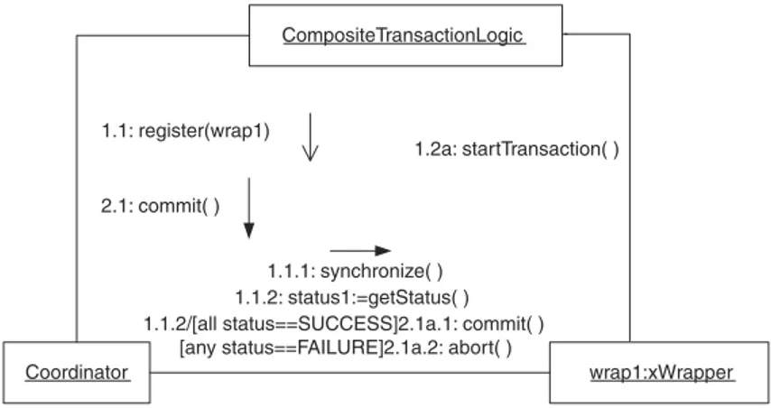
A type of precondition that is not usually indicated with an expression is a requirement that an interaction not start until two or more other inter-actions finish. All interinter-actions have an implicit precondition that they can-not start before the directly preceding interaction finishes. An interaction numbered 1.2.4 cannot start until the interaction numbered 1.2.3 completes.
Some interactions are required to wait for additional interactions to complete before they can start. Such additional predecessor interactions are indicated by listing them at the left side of the interaction followed by a slash (/) and the rest of the interaction. The collaboration diagram in Figure 2.30 contains an example.
In Figure 2.30, the interaction labeled 2.1a.1 cannot start until inter-action 1.1.2 finishes. If an interinter-action must wait for more than one addi-tional interaction to finish before it starts, they all appear before the slash, separated by commas.
The mechanisms discussed so far determine when the methods of a collaboration are called. They do not say anything about when method calls return. The arrows that point at the objects whose methods are called provide information about when the methods may return.
Most of the arrows in Figure 2.30 have a closed head, which indicates that the calls are synchronous. The method calls do not return until the method has completed doing whatever it does.
An open arrowhead indicates an asynchronous method call.An asyn-chronous method call returns to its caller immediately, while the method does its work asynchronously in a separate thread. The collaboration dia-gram in Figure 2.31 shows an asynchronous method call.
CompositeTransactionLogic
wrap1:xWrapper Coordinator
1.1: register(wrap1)
2.1: commit( )
1.1.1: synchronize( ) 1.1.2: status1:=getStatus( ) 1.1.2/[all status==SUCCESS]2.1a.1: commit( )
[any status==FAILURE]2.1a.2: abort( )
1.2a: startTransaction( )
The UML defines arrowheads only for synchronous and asyn-chronous calls. As extensions to the UML, the UML allows other types of arrows to indicate different types of method calls. To indicate a balking call, this book uses a bent-back arrow, as shown in Figure 2.32.
When a balking call is made to an object’s method and no other thread is executing that object’s method, then the method returns when it is finished doing what it does. However, when a balking call is made and another thread is currently executing that object’s method, the method returns immediately without doing anything.
You may have noticed that the object making the top-level call that initiates a collaboration is not shown in all of the preceding collaboration diagrams, which means the object that initiates the collaboration is not considered to be a part of the collaboration.
Up to this point, the objects you have seen how to model in the UML are passive in nature. They do nothing until one of their methods is called.
Some objects are active. A thread associated with them allows them to initiate operations asynchronously and independently of whatever else is going on in a program. Active objects are indicated with a thick border. Figure 2.33 contains an example of an active object.
Figure 2.33 shows an active Sensorobject that calls a Sensor-Observerobject’s method without another object first calling one of its methods.
Statechart Diagram
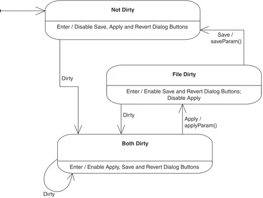
Statechart diagrams are used to model a class’s behavior as a state machine. Figure 2.34 is an example of a simple state diagram.
A statechart diagram shows each state as a rounded rectangle. All of the states in Figure 2.34 are divided into two compartments. The upper compartment contains the name of the state. The lower compartment con-tains a list of events to which the object responds while in that state without
:Client 1: write(:String) :IOManager
FIGURE 2.31 Asynchronous method call.
:ToiletController 1: flush()
changing state. Each event in the list is followed by a slash and the action it performs in response to the event. UML predefines two such events:
•
Theenterevent occurs when an object enters a state.•
Theexitevent occurs when an object leaves a state.If there are no events that a state responds to without changing state, then its rectangle is not divided into two compartments. Such a state is drawn as a simple rounded rectangle that contains only the state’s name.
s:Sensor
:SensorObserver 1: notify(s)
1
1
FIGURE 2.33 Active sensor.
Enter / Disable Save, Apply and Revert Dialog Buttons
Not Dirty
`
Enter / Enable Save and Revert Dialog Buttons; Disable Apply
File Dirty
`
Save / saveParam()
Enter / Enable Apply, Save and Revert Dialog Buttons
Both Dirty
`
Apply / applyParam() Dirty
Dirty
Dirty
Every state machine has an initial state that is the state an object is in before the first transition occurs. The initial state is drawn as a small solid circle.
Transitions between states are shown in statechart diagrams as lines between states. Normally, transition lines are required to have a label indi-cating the event that triggers the transition. The event may be followed by a slash and the action that occurs when the transition takes place.
If a statechart includes a final state, the final state is drawn as a small solid circle inside a larger circle.
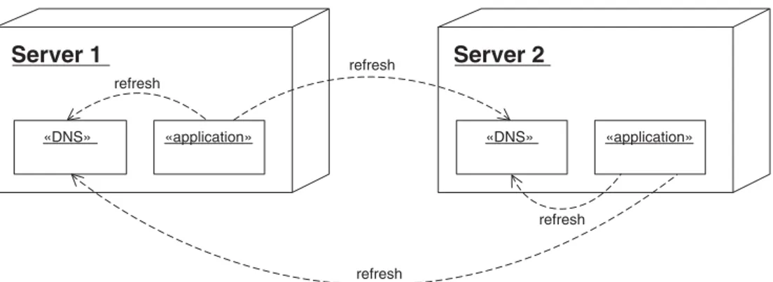
Deployment Diagram
Deployment diagrams show how software is deployed onto computing ele-ments. Figure 2.35 is an example of a deployment diagram.
Figure 2.35 shows two computing elements labeled Server1and
Server2. The UML terminology for computing element is node.Because this book uses nodeto mean other things, the term computing elementis used instead.
The smaller boxes inside the computing elements are software com-ponents. A component is a collection of objects that are deployed together. Each of the computing elements in the diagram contains two components: a DNS component and an application component.
Communication between components is indicated by dashed lines. The dashed lines in Figure 2.35 indicate that the applicationcomponents send messages to the DNScomponents. The dashed lines are labeled refresh.
Server 2
«DNS» «application»
refresh Server 1
«DNS» «application» refresh
refresh
refresh
C
H
A
P
T
E
R
The Software Life Cycle
29
As stated previously, this book is devoted to patterns used during the object-oriented design phase of the software life cycle. In order to provide some perspective on how object-oriented design fits into the process of building and maintaining software systems, this chapter presents a very brief overview of the software life cycle.
A variety of activities take place during the lifetime of a piece of software. Figure 3.1 shows some of the activities that lead to software deployment.
Figure 3.1 is not intended to show all of the activities that occur during a software project, merely the more common ones. This is a typical context for using the patterns discussed in this work. Other books I’ve written on Java patterns describe recurring patterns that occur during the portion of the software life cycle labeled “Build” in Figure 3.1.
Figure 3.1 shows very clear boundaries between each activity. In practice, the boundaries are not so clear. Sometimes it is difficult to say if a particular activity belongs in one box or another. The precise boundaries are not important. What isimportant is to understand the relationships between these activities.
Earlier activities, such as defining requirements and object-oriented analysis, determine the course of activities that follow them, such as
fining essential use cases or object-oriented design. However, in the course of those later activities, deficiencies in the products of earlier activities emerge. For example, in the course of defining a use case, an ambiguous or conflicting requirement may become apparent. It may be necessary to mod-ify existing use cases or to write new ones. You must expect such iterations. As long as the trend is for later iterations to produce fewer changes than earlier iterations, consider them part of the normal development process.
Following are brief descriptions of some of the activities shown in Figure 3.1. These descriptions provide only enough information to explain how the patterns discussed in this work apply to a relevant activity.
Business planning. This typically starts with a proposal to build or modify a piece of software. The proposal evolves into a business case.A business case is a document that describes the pros and cons of the software project and includes estimates of the resources required to complete the project. If a decision is made to proceed with the project, then a preliminary schedule and budget are prepared.
Define requirements. The purpose of this activity is to produce a requirements specification that says what the software produced by the project will and will not do. This typically begins with goals and high-level requirements from the business case. Addi-tional requirements are obtained from appropriate sources to produce an initial requirements specification.
30
■ CHAPTER THREEBuild
Business planning: business case, budget
Detailed planning
Usability testing
Object-oriented analysis: low-level essential use cases, conceptual model, sequence diagrams
Design user interface
Object-oriented design: class diagrams, collaboration diagrams,
state diagrams
Logical database design documentationWrite and help Define requirements: requirements specification
Define high-level essential use cases
Create prototype Define high-level system architecture
Coding Physical database design
Testing
Deployment
FIGURE 3.1 Activities leading to software deployment.
TE
AM
As the requirements specification is used in subsequent ac-tivities, necessary refinements to the requirements are discovered. The refinements are incorporated into the requirements specifi-cation. The products of subsequent activities are then modified to reflect the changes to the requirements specification.
Define essential use cases. Ause casedescribes the sequence of events that occurs in a specific circumstance between a system and other entities. The other entities are called actors. Develop-ing use cases improves our understandDevelop-ing of the requirements, analysis, or design on which the use case is based. As we develop a better understanding of requirements, analysis, and design, we are able to refine them.
Essential use casesdescribe events in terms of the problem domain. Use cases that describe events in terms of the internal organization of software are called real uses cases.
The use cases most appropriate for refining requirements are high-level essential use cases. They are high level in that they explore the implications on which they are based on, but they do not try to add additional details.
Create prototype. Create a prototype of the proposed software. A prototype can be used to get reactions to a proposed project. Re-actions to a prototype can be used to refine requirements and essential use cases.
Define high-level system architecture. Determine the major com-ponents of the system that are obvious from the original pro-posal. Also, determine their relationships.
Object-oriented analysis. The purpose of this activity is to understand what the software produced by the project will do and how it will interact with other entities in its environment. The goal of analysis is to create a model of what the software is going to do, but not how to do it. The products of object-oriented analysis model the situation in which the software will operate from the perspective of an outside observer. The analysis does not concern itself with what goes on inside the software.
Object-oriented design. The purpose of this activity is to deter-mine the internal organization of the software. The products of the design effort identify the classes that will comprise the inter-nal logic of the software. They also determine the interinter-nal struc-ture of the classes and their interrelationships.
includes more patterns that apply to object-oriented design than to any other activity.
Coding. The purpose of this activity is to write the code that will make the software work.
C
H
A
P
T
E
R
Transaction Patterns
33
Acid Transaction(37)Composite Transaction(55)
Two Phase Commit(65)
Audit Trail(75)
Atransactionis a sequence of operations that change the state of an object or collection of objects in a well-defined way that guarantees a con-sistent outcome. A transaction is useful because it satisfies constraints about the state of an object before, during, or after that transaction. For example, a particular type of transaction may satisfy a constraint that an object’s attribute must be greater after the transaction than it was before the transaction. Sometimes, the constraints are unrelated to the objects that the transactions operate on. For example, a transaction may be required to take place in less than a certain amount of time.
Transactions play an important part in many different types of appli-cations. Here are just a few examples:
•
Transactions are important for automatic teller machines. They must never dispense money without deducting it from a customer’saccount or, conversely, deduct money from a customer’s account without dispensing cash.
•
A program that assigns network addresses to computers must never assign the same address to two different computers. A transaction can be used to ensure this.•
A number of computer manufacturers have programs that allow cus-tomers to order computers in custom configurations. When process-ing such an order, the program must generate a transaction that allocates exactly the right quantity of each part that is needed.The patterns in this chapter provide guidance in selecting and com-bining constraints for common types of transactions. Figure 4.1 shows how the patterns in this chapter build on each other.*
The first and most fundamental pattern to read is the ACID Transaction pattern. It describes how to design transactions that never have inconsistent or unexpected outcomes. The Composite Transaction pattern describes how to compose a complex transaction from simpler transactions. The Two-Phase Commit pattern describes how to ensure that a composite transaction is atomic. The Audit Trail pattern describes how to maintain a historical record of ACID transactions.
In addition to being related to transactions, the patterns in this chap-ter also share the fact that they are usually implemented using software that you buy rather than build. For this reason, the focus of these patterns is the use of the solutions that they describe rather than their implementa-tion.
You may notice the lack of code examples in this chapter. It is the author’s opinion that the patterns in this chapter are too high level for con-crete code examples to be useful. The application of these
transaction-FIGURE 4.1 Transaction pattern map.
* Figure 4.1 is not a UML diagram.
Composite Transaction
ACID Transaction
Two Phase
related patterns is readily understood at the design level. However, there is generally no clear relationship between individual pieces of code and the fact that they are part of a transaction. In many cases, objects are unaware of the transactions they participate in.
Throughout this chapter, what is done to a partially completed trans-action that cannot complete is called aborting.Within the context of databases, it is more common to refer to this as rolling backa transaction. Because these patterns are presented in a broader context that includes application-level transactions, the term abortis used instead of roll back.
SYNOPSIS
Ensure that a transaction will never have an unexpected or inconsistent outcome. This is accomplished by ensuring that the transaction has the ACID properties: atomicity, consistency, isolation, and durability.
CONTEXT
Suppose you are developing software for a barter exchange business. It works as a clearinghouse for an indirect barter. For example, a hotel chain offers vouchers for a stay in one of its rooms in exchange for new mat-tresses. The clearinghouse matches the hotel with a mattress manufacturer that spends a lot of money on business trips. The clearinghouse also facili-tates the exchange of the vouchers for the mattresses.
Every transaction that the system handles consists of an exchange of goods or services. Each transaction must correctly update the system’s model of who is supposed to exchange what goods and services with whom. The system must not lose any transactions. The system must not duplicate any transactions. The system must ensure that two different clients do not make a deal for the same goods or service.
FORCES
⁄ You want the result of a transaction to be well-defined and pre-dictable. Given only the initial state of the objects in a transaction and the operations to perform on the objects, you should be able to determine the final state of the objects. For example, given an amount of money in a bank account and an amount of money to be deposited, the outcome of a transaction to deposit the money should result in the account balance being increased by the amount of the deposit. Even if the nature of the transaction is nondeterministic (that is a simulated roll of dice), given the initial state of the object involved you should be able to enumerate the possible outcomes.
⁄ Once started, a transaction may succeed. It is also possible for a transaction to fail or abort. There are many possible causes for a transaction to fail. Many causes may be unanticipated. Even if a
transaction fails, you don’t want it to leave objects in an unpre-dictable state that compromises their integrity.
⁄ A transaction can fail at any point. If there is a failure at a random point in the transaction, additional operations may be required to bring the objects involved into a predictable state. Determining what operations to perform may be difficult or impossible if a failed trans-action can put objects in a state that violates their integrity.
⁄ You want the outcome of transactions to depend only on two things:
•
Initial state of the objects the transaction acts on•
Specific operations in the transactionYou do not want the outcome of a transaction to depend on anything else. In particular, if transactions are performed concurrently, you do not want their concurrency to affect the result of the transactions.
⁄ If the results of a transaction are stored in volatile (nonpersistent) memory, then the observed results of the transaction are less pre-dictable. The contents of volatile memory can change unpredictably. More generally, the observed results of a transaction are unpre-dictable if they do not persist as long as objects that are interested in the results or until another transaction changes the state of the affected objects.
Ÿ The requirements for some applications imply that the progress of some of their transactions can be observed by some other transac-tions. This is often true for long-lived transactransac-tions. For example, an inventory application for a chain of retail stores may support a trans-action to order additional merchandise from a warehouse. The appli-cation may also require that users can query the state of the
transaction:
•
Does the warehouse have it in stock?•
Is it in transit?•
When will it be shipped?•
When will it arrive?Satisfying all of the forces listed in this section may add complexity and overhead to the implementation of a transaction. The nature of some transactions ensures a satisfactory outcome without having to address all of the forces. For example, if there will be no concurrent transactions, then there is no need to address the possibility that concurrent transactions could interfere with each other. Also, if the outcome is the same whether a transaction is performed once or more than once, then recovery from cata-strophic failure can be simplified.
SOLUTION
You can ensure that a transaction has a predictable result by ensuring that it has the ACID properties:
Atomic. The changes a transaction makes to the state of objects on which it operates are atomic. This means that either all of the changes happen exactly once or none of the changes happen. These changes include internal state changes, database changes, transmission of messages, and visible side effects on other pro-grams.
If a transaction is not atomic, then the transaction’s side effects could happen more than once. For example, an auto-matic teller machine (ATM) that does not process transactions atomically may sometimes process that same withdrawal twice. It would be possible for you to make a withdrawal, get your cash, and then a power surge could cause the ATM to process the withdrawal again after you were no longer there.
Consistent. A transaction is a correct transformation of an object’s state. At the beginning of a transaction, the objects on which a transaction operates are consistent with their integrity constraints. At the end of the transaction, regardless of whether it succeeds or fails, the objects are again in a state consistent with their integrity constraints. If all of the transac-tion’s preconditions are met before the transaction begins, all of its postconditions are met after the transaction successfully completes.
Suppose that the software that runs an ATM does not guar-antee the consistency of its transactions. When you make a withdrawal, the amount of cash the machine dispenses might not be the same as the amount deducted from your account.
Isolated. Even though transactions execute concurrently, it appears to each transaction, T, that other transactions execute either before T or after T but not both. That means that if an object that is involved in a transaction fetches an attribute of an object, it does not matter when it does so. Throughout the lifetime of a transaction, the objects on which the transaction operates will not notice any changes in the state of other objects as the result of concurrent transactions.
result would be that the account balance would reflect one with-drawal or the other, but not both.
Durable. Once a transaction completes successfully (commits), the changes it has made to the state of the object(s) become rela-tively persistent. They will persist at least as long as any object can observe the changes.
If transactions from an ATM are not processed in a way that ensures that they are durable, then it might be possible for a withdrawal to be forgotten.
Because most database managers ensure that transactions performed under their control have these properties, many people think of ACID properties only in connection with database transactions. It is important to understand that the ACID properties are valuable for all kinds of trans-actions, including application-level transactions. For example, consider an application that is responsible for changing the price of gasoline at a gas station. When the price is changed it must be changed in three places: in the database that tells the cash registers how much to charge for gas, on the price displayed on the gas pumps, and on the electronic sign that advertises the price. If the price-change transaction does not exhibit the ACID properties, then the price can become inconsistent in all three places, subjecting the gas station to fines.
The point of this solution is to design transactions so that the trans-action as a whole has the ACID properties. Use a transtrans-action manager to manage as much of the transaction as you can. Database engines are the most common transaction managers in business applications.
Using a transaction manager is not enough if portions of a transac-tion are not under its control. For example, if an ATM does not functransac-tion under the control of a transaction manager, it must be integrated with por-tions of a transaction that are under the control of a transaction manager to ensure that the actions of the ATM are atomic.
CONSEQUENCES
⁄ Use of the ACID transaction pattern makes the outcome of
transac-tions predictable.
Ÿ Use of the ACID transaction pattern can substantially increase that
amount of storage required by a transaction. The additional storage requirement arises from a need to store the initial state of every object involved in a transaction so that if the transaction fails it is possible to restore the initial state of the objects it acted on.
Maintaining the isolation of a transaction may require the copying of objects to allow a high level of concurrency. The purpose of the
40
■ CHAPTER FOURTE
AM
copies is to allow the original object to be modified while an unchanging copy of the original is visible to other transactions. Without the copies, it would be necessary to prevent transactions that need to see the original version of a row from running concurrently with transactions that update the row.
•
ACID transactions are often implemented by transaction logic that manipulates objects indirectly through a mechanism that enforces ACID properties for transactions, such as a database manager. In cases where a transaction’s logic is also responsible for maintaining the transaction’s ACID properties, the complexity of the transaction logic may be greatly increased. Using a separate mechanism that enforces the ACID properties makes it much easier to correctly imple-ment the logic that drives a transaction.IMPLEMENTATION
The simplest way to ensure the ACID properties of a transaction is for the transaction logic to manipulate the state of objects through a tool such as a database manager that automatically enforces the ACID properties. If a program works with transactions that will not involve persistent data or objects, the performance penalty introduced by a database manager that persists data may be undesirable. Such applications may be able to take advantage of in-memory databases, which do not incur the overhead of saving data to disk.
Sometimes it is not possible to use any tool to enforce ACID proper-ties. The common reasons for this are performance requirements and a need to keep the size of an embedded application small. Adding logic to an application to enforce the ACID properties for its transaction can introduce a lot of complexity i