UNIVAC
SYSTEM DESCRIPTION
IIO~CESSOR
This manual describes a UNIVAC system. It is as complete and accurate at the time of publication as is feasible by current documentation techniques. The Univac Division w ill issue com plete revis io ns of this m 2.nua 1 when necessa ry. The Univac Division reserves the right to make such additions, corrections, and/or deletions as, in the judgment of the Univac Division, are required by the development of its systems. To assure that you have the current version of this manual and for the current status of the system, contact your local Univac Representative.
UNIVAC is a registered trademark of Sperry Rand Corporation.
Other trademarks of Sperry Rand Corporation appearing in th e text of this publication are:
UNISERVO FASTRAND UNISCOPE PAGEWRITER
~~V:j046~,
___
U._N_I_V_A_C_l_10_8_SY_S_T_E_M_D_E_S_C_R_1_P_T_I._O_N _ _ _
-'-_ _ _ _
---II~Sc_Eo_Cn_T~_:_~t_:S_...II
....
F>_A_G_E_:1 _
CONTENTS
1. INTRODUCTION
2. SYSTEM [)ESCRIPTION
2.
1.
G ENE R A L2.2. SYSTEM COMPON ENTS
2.2.1.
Central Processor 2.2.2. Input/Output Controller2.2.3.
M ai n Sto rage2.2.4.
Auxiliary Storage2.2.5. Interconnection Components
2.2.5.1.
Shared Peripheral Interface2.2.5.2.
Multi-Module Access Unit2.2.5.3. Availability Control Unit
2.2.6.
Display Console2.3.
CONFIGURATIONS2.4.
U N I V A CAR RAY PRO C E S SO R3. MAIN STORAGE
3.1.
GENI:RAL3.2. STORAGE MODULE
3.3.
MULTI-MODULE ACCESS UNIT (MMA)3.4.
PACKAGING3.5. STORAGE CAPACITY
3.6. ADDHESSING
:l.6.1.
Overlapping3.6.2.
Interleaving3.7. STORAGE PROTECTION 3.7.1. Storage Protection Modes 3.7.1.1. Privileged Mode
3.7.1.2.
User Program Mode3.8. RELATIVE ADDRESSING
CONTENTS
1
to
61-1
to
1-12-1
to
2-122-1 2-1 2-2 2-2
2-3
2-3
2-4
2-4
2-7
2-7
2-8
2-9
2-123-1
to
3-5UP-4046 Rev. 3
4.
UNIVAC 1108 SYSTEM DESCRIPTION
1108 PROCESSOR
4,1. GENERAL
4.2. PRINCIPAL SECTIONS
4.3. INSTRUCTION WORD FORMAT 4.3.l. Fun cti on Code - f Fi el d
4.3.2. Partial-Word or Immediate-Operand Designator - j Field 4.3.3. Control Register Designator - a Field
4.3.4. Index Register Designator - x Field 4.3.5. Index Modification Designator - h Field 4,3.6. Indirect Address Designator - i Field 4.3.7. Address Field - u Field
4.4. CONTROL REGISTERS 4.4.1. Index R egi sters
4.4.2. Arithmetic Accumulators 4.4.3. Access Con tro I Regi ste rs 4.4.4. R Registers
4.4.4.1. RO - Real Time Clock 4.4.4.2. R1 - Repeat Counter 4.4.4.3. R2 -Mask Register
4.5. ARITHMETIC SECTION 4.5.l. Th e Adder
4.5.2. Arithmeti c Accumu lators 4.5.3. Partial-Word Transfers 4.5.4. Split-Word Arithmetic 4.5.5. Shifting
4.5.6. Double-Precision Fixed Point Arithmetic 4,5.7. Floating-Point Arithmetic
4.6. EXECUTIVE SYSTEM CONTROL FEATURES 4.6.l. Processor State Register
4.6.2. Interrupts 4.6.3. Guard Mode
4.7. IN STRU CTION REP ERTOI RE 4.7.lo Data Transfer Instructions 4.7.2. Fixed-Point Arithmetic 4.7.3. Floating-Point Arithmetic 4.7.4. Index Register Instructions 4.7.5. Logical Instructions 4.7.6. Sh i ft Ins t ru c t ion s
4.7.7. Repeated Search In stru cti on s 4.7.8. Unconditional Jump Instructions 4.7.9. Conditional Jump Instructions 4.7.10. Test(or Skip) Instructions
4.7.11. Executive System Control Instructions 4.7.12. Input/Output Instructions
4.7 .13. Oth er In stru cti on s
Contents
SECTION: P AGE:
4-1 to 4-21
Rev. 3 UNIVAC 1108 SYSTEM DESCRIPTION SECTION: Contents
3
P AGE:
UP·, 4046
~
---~---5. SHARED PROCESSING SYSTEM
5.1. GENERAL
5.2. SYSTEM COMPONENTS 5.2.1. Input/Output Processor 5.2.2. Computational Processor 5.2.3. Main Storage
5.2.4. Au xi Ii ary Sto rage 5.2.5. Peri ph era I Su bsy stem s
6. PROCESSOR INPUT/OUTPUT CONTROL SECTION
6.1. GEN ERAL DESCRIPTION
6.2. PERIPHERAL CONTROL
6.3. INTERNALLY SPECIFIED INDEX MODE
6.4. EXTERNALLY SPECIFIED INDEX MODE
6.5. BU FFER MODE DATA TRANSFERS
6.6. INPUT/OUTPUT IN FORMATION WORDS 6.6.1. Data Wo rds
6.6.2. Function Words 6.6.3. Identifier Words 6.6.4. Statu s Wo rds
6.7. PRIORITY CONTROL
6.8. INPUT/OUTPUT INSTRUCTIONS 6.8.1. Monitored Instructions
7. THE INPUT/OUTPUT CONTROLLER
7.1. GENERAL DESCRIPTION
7.2. POINTER REGISTERS
7.3. ESI AND lSI
7.4. COMMAND AND CONTROL WORDS 7.4.1. IOC Command Word
7.4.2. Data Chaining
7.4.3. External Function Access Control Word 7.4.4. Data Access Control Word
8. PERIPHERAL SUBSYSTEMS
8.1. AVAILABLE PERIPHERAL EQUIPMENT
8.2. TH E FLYING HEAD DRUMS
8.2.1. FH-432/FH-1782 Magnetic Drum Subsystems 8.2.2. FH-432 Magnetic Drum Subsystem
8.2.3. FH-1782 Magnetic Drum Subsystem 8.2.4. FH-880 Magnetic Drum Subsystem
5-1 to 5-4
5-1 5-2 5-2 5-2 5-2 5-3 5-3
6-1 to 6-7
6-1 6-1 6-1 6-2 6-4 6-4 6-5 6-5 6-5 6-5 6-5 6-6 6-7
7-1 to 7-~
7-1 7-1 7-3 7-3 7-4 7-4 7-5 7-5
8-1 to 8-25
UP-4046
Rev. 3 UNIVAC 1108 SYSTEM DESCRIPTION
8.3. MASS STORAGE SUBSYSTEMS
8.3.1. FASTRAN 0 Mass Storage Subsystems
8.3.2.
UNIVAC8414
Disc Subsystem8A.
UNISERVO MAGNETIC TAPE SUBSYSTEM8.4.1.
UNISERVO VI-C Magnetic Tape Subsystem8.4,2.
UNISERVO VIII-C Magnetic Tape Subsystem8.4.3. UNISERVO
12
Magnetic Tape Subsystem8,4.4. UNISERVO
16
Magnetic Tape Subsystem8,5.
UNIVAC HIGH SPEED PRINTER SUBSYSTEM8.6.
PUNCHED CARD SUBSYSTEM8.6.1.
UNIVAC Card Reader8.6.2.
UN I V AC Card Pu n ch8.7.
UNITIZED CHANNEL STORAGE SUBSYSTEMDATA COMMUNICATIONS
9.1. GENERAL
9,2.
UNIVAC1108
COMMUNICATIONS SUBSYSTEM9.3. SYNCHRONOUS DATA TERMINALS 9.3.1. Word Terminal Synchronous
9.3.2.
Communication Terminal Synchronous9.4.
UNIVAC DATA COMMUNICATION TERMINAL (OCT)2000
9.5. UNIVAC DATA COMMUNICATION TERMINAL (OCT)
1000
9.6.
UNIVAC COMMUNICATION TERMINAL (OCT)500
9.7. UNISCOPE
300
VISUAL COMMUNICATION TERMINAL SUBSYSTEM9.7.
1.
The K ey boa r d9.7.2. CRT Display
9.7.3. Subsystem Configurations 9.7.4. Rei i a b iii ty
9.7.5. Special Features
9,8.
UNISCOPE100
VISUAL COMMUNICATION TERMINAL SUBSYSTEM9,9.
UNIVAC9200/9300
ONSITE/REMOTE SUBSYSTEMS9.10.
THE UNIVAC DATA COMMUNICATION SUBSYSTEM (DCS-1)Contents SECTION:
8-8
8-8
8-11
8-13
8-14
8-16
8-18
8-19
8-21
8-23
8-23
8-24
8-25
P AGE:
9-1
to9-19
Rev. 3
UNIVAC 1108 SYSTEM DESCRIPTION
SECTION: Contents5
P AG E:
UP-4046
l
---,---
.,---.---~---~~---~---10. PROGRAMMED SYSTEMS SUPPORT
10.1.
AVAILABLE SOFTWARE10.2.
TH E EX EC U TIV E SY STEM10.2.1.
Multiple Modes of Operation10.2.1.1.
Batch P rocessi ng10.2.1.2.
Demand" Processing (Time-Sharing)10.2.L3.
Real Time10.2.1.4.
Multiprogramming10.2.2.
Techniques for Utilization of Mass Storage10.2.3.
The Primary Functional Areas of the Executive System10.2.3.1.
Executive Control Language10.2.3.2.
Th e Supe rvi so r10.2.3.3.
Time Slicing10.2.3.4.
Storage Compacting10.2.3.5.
Facilities Assignment10.2.3.6.
The File-Control System10.2.3.7.
Operator Communications1O.2.3.S.
Diagnostic System10.2.3.9.
Input/Output Device Handlers10.2.3.10.
Auxiliary Processors10.2.3.11.
Utilities10.2.3.12.
Processor Interface Routines10.2.3.13.
System Setup10.
3. THE. ASS EM B L E R10.3.1.
Symbolic Coding Format10.3.2.
Assembler Directives10.3.3.
Additional Features10.4.
FORTRAN V10.4.1.
Language Extensions and Enhancements10.4.2.
Compi ler Organization10.5.
CON VE RSATION AL FO RTRAN' V10.5.1.
System Featu res10.5.2.
System Concepts1l0.5.3.
Conversational FORTRAN Processor and the Executive System10.5.4.
Conversational FORTRAN Language10.6.
LIFT, FORTRAN II TO FORTRAN V TRANSLATOR10.7.
COBOL10.7.1.
FD ANSI COBOL10.7.1.1.
ANSI Standard COBOL Features1lO.7.1.2.
Extensions to FD ANSI Standard CO BOL10.7.2.
DOD COBOLII
0.7.
2.1. DO 0 COB 0 L Fe a tu res10.7.2.2.
Extensions and Special Features of DOD COBOL10.7.3.
Operational Characteristics10.S.
ALGO L1,0.9.
SO Rl/M ERG E10.10.
MATHEMATICAL FUNCTION PROGRAMS10-1
to10-29
10-1
10-2
10-2
10-2
10-2
10-2
10-3
10-3
10-3
10-3
10-4
10-4
10-4
10-5
10-5
10-5
10-6
10-6
10-6
10-6
10-6
10-6
10-6
10 .... 7
1O~7
10-7
10-7
lO-S
10 .... 12
UP-4046
Rev. 3
UNIVAC 1108 SYSTEM DESCRIPTION10.11.
APPLICATION PROGRAMS10.11.1.
Linear Programming System10.11.2.
APT III10.11.3.
PERT10.12.
MATH-PACK10.13.
STAT-PACK10.14.
G EN ERAL PU RPO SE SYST EM SIMU LA TOR10.15.
SIMULA10.16.
FUNCTIONAL MATHEMATICAL PROGRAMMING SYSTEM (FMPS)APPENDIXES
A. NOTATIONAL CONVENTIONS
B. SUMMARY 0 F WORD FO RMA TS
C. INSTRUCTION REP ERTOI RE BY FUNCTION CODE
D. MATH.PACK ROUTINES
E. STAT.PACK ROUTINES
FIGURES
1-1.
The Central Processor and Operator's Console2-1.
The Input/Output Controller2-2.
Shared Peripheral Interface (SPI), Single-Channel Subsystem2-3.
Shared Peripheral Interface (SPI), Dual-Channel Subsystem2-4.
Multi-Module Access Unit2-5.
Unit Processor System with Noninterleaved Storage2-6.
Single Processor with I/O Controller and Interleaved Storage2-7.
Mu Iti-Processor System4-1.
Control Register Address Assignments4-2.
j-Determined Partial-Word Operation4-3.
Processor State Register Format5-1.
UNIVAC1108
Shared Processing System7-1.
The Input/Output Controller9-1.
CTMC SubsystemTABLES
4-1.
Fixed-Address Assignments9-1.
OCT2000
Field-Installable OptionsContents SECTION:
10-21
10-21
10-22
10-22
10-23
10-24
10-24
10-25
10-26
PAGE:A-I
toA-2
B-1 to B-2
C-l
toC-9
0-1
to0-4
E-l
toE-4
UP··4046
Rev. 3 UI~IVAC
1108 SYSTEM DESCRIPTION
SECTION:1
1
PA G E: ---~~.-- ...
--
... ~...
--
...
~...
~...
----
...
1. INTRODUCTION
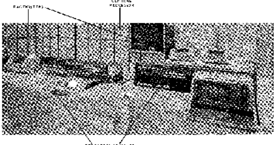
Figure 7 -7. The Central Processor and Operator's Console
The UNIVAC 1108 Multi-Processor System - the logical, program compatible successor to the UNIVAC 1107 Thin-Film Computer - is an integration of system-oriented hardware design, imaginati ve development, and programming technology, The result is a system that effecti vely knows no application boundaries, It is equally effectual in real-time, scientific, or data processing environments, and is capable of adjusting dynamically to anyone or a mixture of these environments,
2
1
Rev. 3 Ut4lVAC 1108 SYSTEM DESCRIPTION SECTION: P AGE:
UP-4046
.l
---
,---.---~---~---~---2. SYSTEM DESCRIPTION
2.1. GENERAL
The UNIVAC 1108 Multi-Processor System is a general purpose, high performance unit and multiprocessor system, incorporating the latest advances in computer design, systems organization, and programming technology. Its modular structure permits the selection of systems components to fulfill most efficiently the speed and capacity requi rem ents for applications ranging from a basic j ob- shop sy stem to the comp reh en si v e public utility computing complex.
As the workload increases, this modularity also enables the addition of input/output subsystems and main storage and even additional processors to provide the full multi-processor system. Among the principal features of the UNIVAC 1108 System are:
• Common resource system s organization
• Equality among multiple UNIVAC 1108 Central Processors • M ultip 1 e input/output controll ers
• Large, modular, parity-checked, high-speed main storage
• Overlapped and interleaved main storage access (for multimodule storage) • Redundancy among system s components
• Program address reI oc ation • Storage protection
• Partial-word addressability in 6, 9, 12, and 18-bit portions as well as full-word (36 bits and double-word (72 bits) addressing
• High speed, random access, auxiliary storage • Privileged mode for the Executive system • Guard mode for user program s
2.2. SYSTEM COMPONENTS
The UNIVAC 1108 System is organized to allow multiple processors to perform a number of tasks simultaneously under the direction of a common Executive control system. A multiprocessor system requires a much higher degree of modularity in organization than does a unit-processor system. It must be divisible into individual logical components with the following properties:
• Each system component must have more than one access path. • Priority logic must resolve possible access conflicts.
• The failure of any individual component must not prevent continued operation of the system.
uP- 4046 Rev. 3
2
UNIVAC 1108 SYSTEM DESCRIPTION SECTION: PA G E:
The system is constructed of six types of components:
• Central Processor Units (CPU) • Input/O utpu t Controllers (10 C) • Main Storage Modules
• Auxiliary Storage Subsystems • Sy stem s I nterconnection Component s • Peripheral Subsystems
A shared-p rocesso r system inco rpo rates two processors (computational and inpu t/ ou tpu t) which offer a considerably greater capacity than the unit processor.
2,2.1, Central Processor
Each processor can perform all functions required for the execution of instructions including arithmetic, input/output, and Executive control. In a multiprocessor con-figuration, all processors are equal - the test of a true multiprocessor system. Included in each processor is its own set of 12S-nanosecond integrated circuit control registers providing multiple accumulators, index registers, input/output access control registers, and special-use registers.
In the shared processor system, the computational processor has only control and arithmetic sections for computation. The I/O processor consists of an I/O section for data transfer, and arithmetic and control sections for computations during idle input! output cycles. This increases throughput and provides a balanced system under direction of the Executive without special programming by the user. It can be expanded to a multiprocessor system without changes to software.
2.2.2, Input/Output Controller
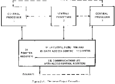
The I nput/O utput Controller (F igu re 2-1) is an indep enden t processo r utili zed in mul tip roc esso r sy stem s to expand th e input/output capab ilitie s of the syst em. It includes:
• Up to 16 high- speed i nput/ output chann el s • Independent access to main storage • Data chaining
• Sixteen pointer registers
• Sixty-four external function and lSI data access control regi sters • 192 communications access control registers
• An optional 256 additional communications access control registers
2
3
SECTION: P A GEl
UP .. ·4046
~
Rev. 3 , _ _ _ _ ~_~
UNIVAC 1108 SYSTEM DESCRIPTION
_ _ ~~~ _ _ _ _ _ _ _ _ _ _ _ _ _ _ _ _ _ _ _ _ _ _ _ _ ~ _ _ _ _ _ _ _ _ ~~ _ _ _ _ _ _ _ _ _ M _ _ _ _ _ _ _r - - - ,
t
CENTRAL PROCESSOR
1
~---~
CENTRAL PROCESSOR
2
16 POINTER REGISTERS
CHANNEL
64 EXTERNAL FUNCTION AND lSI DATA ACCESS CONTROL REGISTERS
192 COMMUNICATIONS (ESI) DATA ACCESS CONTROL REGISTERS
l
_ _ _ _ - - - -15
Figure 2-7. The Input/Output Controller
2.2.3. Main Storage
t
CENTRAL PROCESSOR
3
The main storage of the UNIVAC 1108 System is expandable in 65,536-word incre-ments up to a maximum of 262,144 thirty-six bit wordso The main storage read/restore cycle time is 750 nanosecondso Up to four logical banks for instruction/data reference overlapping provide the capability for an effective cycle time of 375 nanosecondso In addition, two-way interleaving of storage modules is provided to reduce the probability of access conflictso
2.2.4. Auxiliary Sto rage
The auxiliary magnetic drum storage subsystems are an integral part of each UNIV AC 1108 System" Up to eight FH-432, FH-1782, or FH-880 magnetic drums, or any com-bination of the FH-432 and FH-1782 types, may be attached to one or two control uni tso Both the FH -432 and FH -1782 typ es of drum can transfer data at 1,440,000 cha racters per secondo The type FH -880 transfer ra te is 360,000 cha ra cters per secondo The average acces s tim e of th e FH -432 is 4.3 milli second s; th e access tim e of the FH-1782 and FH-880 is 17 millisecondso
UP-4046
Rev. 3 UNIVAC 1108 SYSTEM DESCRIPTION SECTION: 2 P AGE:
2.2.5. Interconnection Components
It is an essential characteristic of multiprocessor systems that there must be provision for sharing all of the main storage and all of the I/O subsystems by all processors in the system, This sharing must be on the basis of both established p.riorities and reactive priorities that may change du~ing processing, In the 1108 System, Multi-Module Access Units (MMA) provide this access to the storage modules by several processors, and the Shared Peripheral Interface (SPI) similarly enables the sharing of I/O subsystem s among processors,
2.2.5.1. Shared Peripheral Interface
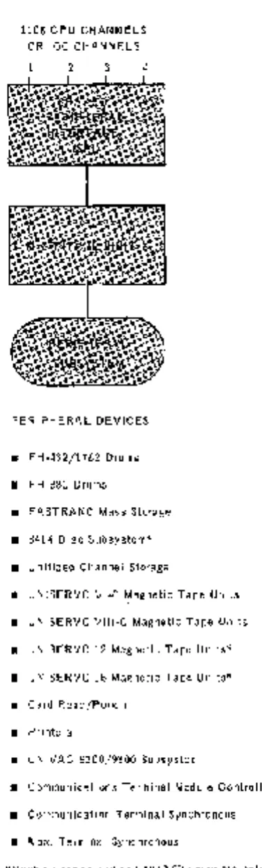
The Shared Peripheral Interface (SPI) controls the access of up to four input/output channels to units in a shared peripheral subsystem (see Figure 2-2), Access to shared peripheral subsystems is determined primarily by time of request,
If two requests are made simultaneously, the Central Processor or Input/Output Controller on the lower numbered SPI input/output channel receives priority. In case of a busy condition, or a priority conflict, the Executive automatically stacks the request until the SPI channel is available, First-level queuing is handled in the SPI itself. The Executive stacks longer queues and keeps track of the num ber of I/O function requests outstanding,
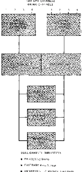
Input/output subsystem s may be either single- or dual-channel as is illustrated in Figures 2-2 and 2-3, Single-channel subsystems perform one I/O operation at a time and therefore require one control unit, one I/O channel, and, in multiprocessor systems, only one SPL Dual channel subsystems can execute two operations simultaneously using different peripheral units in the subsystem, Both of these operations may originate in the same processor or they may come from different processors,
Different processors can be connected to such a dual-channel subsystem through two SPI units, Two input/output channels from each Central Processor or Input/Output Controller take separate paths, The failure of an SPI or one of the pair of control units affects only one of the two paths to a peripheral subsystem. Therefore, all peripheral units are still accessible through the second SPI and control unit.
__ U_P_-_4_0_4_6_
Rev. 3
--L--_
1. _________________________________________ U~IIVAC1108 SYSTEM DESCRIPTION
~
________~
_____ SECTION:2 ____
~
________
PAGE:5
1108 CPU CHANNELS OR IOC CHANNELS
2 3 4
PERIPHERAL DEVICES
• FH-432/1782 Drums • FH-880 Drums
• FASTRAND Mass Storage • 8414 Disc Subsystem* • Unitized Channel Storage
• UNISERVO VI-C Magnetic Tape Units • UNISERVO VIIIQC Magnetic Tape Units • UNISERVO 12 Magnetic Tape Units* • UNISERVO 16 Magnetic Tape Units* • Card Read/Punch
• Pr inters
• UNIVAC 9200/9300 Subsystem
• Communications Terminal Module Controller • Communication Terminal Synchronous • Word Terminal Synchronous
*Must be connected to CPU I/O channels only
UP-4046
Rev. 3 UNIVAC 1108 SYSTEM DESCRIPTION
2 3
1108 CPU CHAN NE LS OR IOC CHAN NELS
4 2
DUAL-CHANNEL SUBSYSTEMS
• F H .432/1 782 Dr u m s
• FASTRAND Mass Storage
3
• UNISERVO VIII~C Magnetic Tape Units
• UNISERVO 12 Magnetic Tape Units
• UNISERVO 16 Magnetic Tape Units
• 8414 Disc
2
SECTION:
4
Figure 2-3. Shared Peripheral Interface (SPI), Dual-Channel Subsystem
6
2
7
UNIVAC 1108 SYSTEM DESCRIPTION
P AG E:. UP··4046
~
REV. 3 SECTION:
---
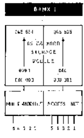
---~~---~~~---~---BANK 1
065 534 065 535
1
65;~~R:~:D
1
MODULE
even odd
000 000 000 001
MUL TI-MODULE ACCESS UNIT
5 4 3 2 1 5 4 3 2 1
Figure 2-4. Multi-Module Access Unit
2.2,5,2, Multi-Module Access Unit
The Multi-Module Access Units (MMA) allow the sharing of individual storage modules by up to three Central P roceSSQrs and two Input/Output Controllers on a fixed priority basis, (See Figure 2-4,)
The MMA recognizes the storage access requests on a priority basis with the lower channel retaining the higher priority, Input/Output Controllers which require higher p rio ri ty are therefo re connected to the lower num bered in terfaces, Upon reco gni tion of a storage access request, the MMA connects the address lines, the CPU or IOC data lines, and the write control signals to the storage module, The MMA then sends the storage acknowledgement back to the recognized processor and provides the drive necessary to transfer the data to the processor requesting iL
2.2.5.3. AVclilability Control Unit
Because of the system availability requirement, the multiprocessor system must have a means for partitioning the system for specific jobs or for maintenance purposes, The Availability Control Unit (ACU) performs this and related functions as follows:
• Partitions the multiprocessor system hardware into independent systems; • Takes units offline for maintenance without disrupting operation of the rest of
the system;
• Prot ect s main stora ge in event of a powe r failure in the CP U 0 r 10 C;
UP - 4046 Rev. 3
2
UNIVAC 1108 SYSTEM DESCRIPTION SECTION:
The ACU partitions the hardware into specific configurations by disabling and enabling the interface between units, It can set up as many as three logically independent configurations which run concurrently under control of the Executi ve system" The po ssibl e configurations can be presp ecified for a given sit e, A t the same time the ACU can take units offline for maintenance,
P AGE:
The ACU is an independent unit with its own power supply which is logically situated between the peripheral su bsy stems, the central processors, inpu t/ outpu t controllers, an d main storage, (See Figure 2-7,) It can interface with th ree Central Processors through one I/O channel of each processor, two IOC's, four banks of main
storage, and six m ul tip Ie-access p eriph eral subsy stem s, A ddi tion al pe ripheral su b-systems, to a maximum of 24, can be added in groups of six, The ACU includes a control panel, physically located at the operator1s console, that indicates all
parti-tioning curren tly in effect and al so show s which un its a re off line, It al so ha s man ual controls to switch units on or off line,
The automatic recovery sequence is based on a resettable system timer in the ACU, The period of this timer can be set to times varying from one to fifteen seconds, Unless the Executive system resets this timer within its period, the ACU assumes that a catastrophic malfunction has occurred and it initiates an automatic recovery sequence, The processor can interrogate the ACU to determine which units are online and available for use,
2.2.6. Display Console
The UNIVAC 1108 Display Console Subsystem is a freestanding input/output device for directing and monitoring the operation of the CPU. A multiprocessor configuration includes one console subsystem for each CPU. The various activities of the system can be apportioned among the available consoles so that the total system will be utili zed to b est a dvan ta ge. The con sole is al ways connected to input/output ch annel 15 of the CPU,
The basic Display Console includes the following components:
• Keyboard and CRT Display
The keyboard and CRT display enable the operator to monitor the performance of the system, The keyboard is a standard four-bank keybo ard which can generate 63 Fieldata codes, A row of eight interrupt keys is located immediately above it. Th e CRT can di spl ay 16 lines of 64 characters each"
• UNIVAC P AGEWRITER Printer
The UNIVAC PAGEWRITER printer provides a hard copy of all messages for a permanent record of all completed transactions between the operator and the Executive system, The PAGEWRITER printer prints lines of up to 80 characters each at a rate of 25 characters per second.
• Day Clock
The day clock on the operator's control panel display s the time of day in hours, minutes, and hundredths of minutes. It furnishes the time of day to the CPU every 600 milliseconds and sends a day clock interrupt signal to the CPU every 6 seconds, The day c lock may be manually di sabled from the ope rator' s control paneL
On a multi processo r sy stem, anyone day clock may be s elected to be active either externally or by program,
2
9Rev. 3 U~IIVAC 1108 SYSTEM DESCRIPTION SECTION: PAGE:
UP-4046
~
,---~---~~---• Operator's Control Panel
The operator's control panel includes fault, disable, and mode indicators for its CP U and a ssociat ed main storage modules. A vailabl e to the op erator are display s and controls associated with selecting and releasing jumps and stops. Also displayed is the Program Address Counter, Memory Select Register, and the time display of the day clock. Accessible to the operator are system controls associated with the CPU and subsystems logically connected to the CPU.
• A ddi tional Features
A n auxiliary righ t- or I eft-w ing console to accommodat e control! di splay panel sis included when using the Communications Terminal Module Controller (CTMC) subsystems.
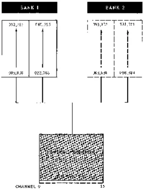
2.3. CONFIGURATIONS
The introduction of the UNIVAC 1108 System with its many components provides a most flexible system. The many configurations of individual components are almost Ii mitl ess. Figures 2-5, 2-6, and 2-7 illustrate typical po ssibiliti es.
BANK 1
032,767
000,000 032,768
CHANNEL 0
BANK 2
.. ---T---,
I
098,303I
131,071I
I
t
I
•
I
I
I
I
I
I
I
I
II
II
I
I
I
I
I
I
I
I
I
I
I
I
I
I
I
II
II
L065,53~1_.::.98,3~..J
15
UP - 4046
Rev. 3 UNIVAC 1108 SYSTEM DESCRIPTION
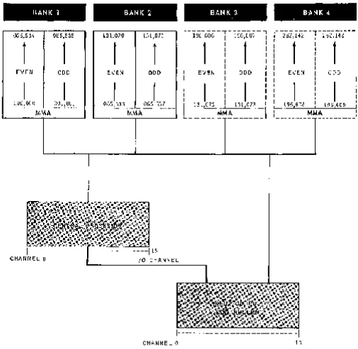
BANK 1 BANK 2 BANK 3
065,534 065,535 131,070 131,071
r---.---,
196,606 196,6071
t
1
t
1
1
EVEN ODD EVEN ODD EVEN ODD
I
I
OOOpOOO 000,001 131
1°72 131,073
MMA
' - - -
-~--- - --- 15
CHANNEL
°
I/O HANNEL2
SECTION: P AGE:
BANK 4
.-
-.---
-,.---262,142 262,143
1
1
EVEN ODD
196,608 1962609
MMA
- - - -
-1- --- - --- -I
CHANNEL
°
15Figure 2-6. Single Processor with I/O Controller and Interleaved Storage
2
11
Rev. 3
,
UNIVAC 1108 SYSTEM DESCRIPTION
SECTION: 1= AGE:, UP-4046
~
----,---
,---~---~---a
CCJ
CCJ
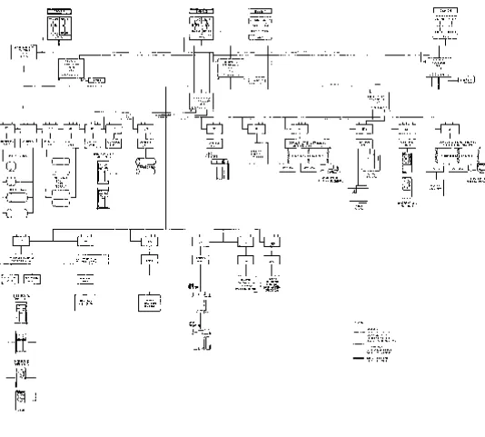
Figure 2-7. Multi-Processor System
up·
4046 Rev. 32
UNIVAC 1108 SYSTEM DESCRIPTION SECTION: P AGE:
2.4. UNIVAC ARRAY PROCESSOR
The UNIVAC Array Processor (UAP) is a special purpose processor used to manipulate large arrays of data such as seismic, geologic, geodetic, weather, medical, and so forth. The U AP is designed to operate as a subsystem with the 1108 Operating System,
12
thus relieving the 1108 processor of the burden of the repetitive manipulation and summations of large arrays. UAP is interfaced by means of an I/O channel and accesses main storage by means of Multi-Module Access (MMA) Units or Shared Memory Interface (SPI).
The UAP is designed to provide a balance between hardwar.e complexity and a maximum of efficiency and flexibility of use. Its design is specifically structured for the specialized tasks of convolution, spectrum analysis, and other array manipulations. The features of the U AP include a 36-bit floating-point capability; fixed-point capabilities include both 36- and 12-bit words.
The U AP has its own arithmetic and indexing registers. It includes 20 hardware instructions for the rapid processing of arithmetic operations associated with matrices or vector
processing. The most important commands are convolution, Fast Fourier Transform (FFT), and interpolation.
The instruction repertoire can have many variations depending upon its function. For example, all add operations can be subtract operations. Control bits (stacking or summing bits) allow the contents of the corresponding destinatio,n addresses to be added to the operation results before sto rage back at the destination.
Several 1108 P roce sso r/ Array configu ration s are po ssible. Th e minim urn configu ration is an Array Processor and one 1108 p rocesso r with 131K main storage capacity. The la rgest configura tion co nsi sts of an Array P rocesso r and two 1108 processo rs with a total storage capacity of 262K main storage.
up-
4.046~
Rev. 3
,---.---~---~---~---3 1
U.HVAC 1108 SYSTEM DESCRIPTION
SECTION: P AGE:3. MAIN STORAGE
3.1. GENERAL
The main storage of the UNIVAC 1108 Multi-P rocessor System is a high performance, fast access repository for instructions and data, Its design fully supports the concepts of multi pro grammin g, m ultip rocessing, modularity, and reliability around which the entire UNIV AC 1108 Multi-Processor System is constructed, Basic featu res of the 1108 m ai n sto rage are:
• 750 nanosecond read/restore cycle time;
• 65,536,131,072,196,608, or 262,144, 36-bit words; • Parity checking on all storage references;
.' Access by up to three central processors and two IOC 's;
• ModuLar expansion of two, four, six, or eight 32,768-word modules (one, two, three, or four 65,536-word module pairs or banks) in multi-module storage;
• Hardware storage protection - lockout boundaries establishable in 512-word increments • ReI aU ve a ddressing an d dynam ic program relocatability th rough program base registers; • Online serviceability - module pairs may be removed for servicing without stopping
the entire system;
• 0 ver] apping/in terleaved main storage acces s in m ul ti-mo dul e storage to boo st p roc esso performance and to minimize access conflicts among processors.
While these features are all discussed generally as storage features, many of them such as rela ti ve addres sing, sto rag e protection, overlappi ng/int erl eav ing are actually function s of each p roc essor. With prop er multiprocessor system 0 rganization, main sto rage b ecom es
a set of components of the system which are alloca'table in the same manner as peripheral devices, In realizing this objective, the design departs from the traditional close inte-gration of the processor and the storage elements in the following ways:
• Main sto rage is com po sed of independen tly acc essi ble mo dul es; yet it present s a continuous addressing structure to the processors,
• In order to service more than one processor, a method of establishing priority among processors (CPU's and IOC's) at each module is provided in case two or more pro-cessors attempt to reference the same module simultaneously,
UP-4046
Rev. 3
3
UNIVAC 1108 SYSTEM DESCRIPTION SECTION:
With these considerations in mind, the main storage modules (by means of the MMA) become passive components which perform the following functions:
• Grant storage access to a number of processors on a priority basis; • Accept an address from any processor;
• Store or retrieve a word at that address;
P AGE:
• Issue an acknowledgem ent signifying that a storage reference has been completed; • Generate or check parity on all data and deliver an interrupt signal to the processor
requesting access should a parity error occur.
This processor/module relationship has significant advantages for the immediate as well as th e fu ture needs of the sy stem. A ddi tion of processors 0 r bank s of sto rage is
simplified. It becomes a simple matter to add processors or storage elements, or to replace them with improved equipment, module by module, as technology advances.
3.2. STORAGE MODULE
The basic sto rage module of m ulti-mo dul e storage incl udes 32,768 words 0 f ferri te
core array. Each word is 36 bits long and carries two additional parity bits in nonaddressable levels, one bit for each half-word. The main components of each type of module are a IS-bit address register, a 36-bit read/restore register, parity checking circuits, and request/acknowledge circuits.
The IS-bit address register of each storage mo dule provides addressing for 32,768 words. Since an I8-bit address is generated within the processor for each storage reference, three bits are available for selection of one of the eight possible storage modules.
Parity is checked on reading or calculated on writing for each storage access. If a parity error is detected, the storage module sends a parity error interrupt signal to the processor which it is currently serving, and rewrites the word in its incorrect form to ensure subsequent data errors when the word is again referenced. Preservation of the error in this way facilitates fault location, since the Executive can determine whether the failure is transient or is associated with a marginal or complete failure of the module.
3.3. MULTI-MODUL E ACCESS UNIT eMMA)
In a multiprocessor system, an MMA unit is connected between each pair of main storage modules and the processors which may reference it. The MMA unit furnishes five
priority-ordered processor connection paths (one for each CPU and one for each IOC) to each of the modules of the pair. Should an access conflict occur among processors, the MMA grants storage access to the processor having the highest priority, then the next, and so on. Communications between a processor and a single storage module can, therefore, be asynchronous; if the storage module is busy servicing one processor, a passi ve w ai t cycle is induc ed in others 0 flower p rio rity that may be req uestin g acce ss.
B ecau se a delay in honoring an inpu
t/
ou tpu t transfer can result in an un desi rabl e2
"go-around" on drum, reread or rewrite on tape, or actual loss of data in the case of real-time input, Input/Output Controllers are ordinarily attached to the higher priority inputs of
3
3
UNIVAC 1108 SYSTEM DESCRIPTION
SEC1'ION: P AG EIUPM
4046
~
Rev, 3
---
,---~---~~---~---3.4. PACKAGING
Two 32,768-word storage modules (module pair) within a single cabinet: constitute a bank. An adjacent cabinet contains dc power supplies for operation of the bank and the associated MMA.
3.5. STORAGE CAPACITY
A vailable storage capacity ranges from 65,536 words to the system maximum of 262,144 words, in steps of 65,536 words, according to the following:
• 65,536 wo rds (two modul es) - Minimum fo r unit pro cessor sy stem
• 131,072 words (four modules)- Minimum for multiprocessor system
• 196,608 words (six modules)
• 262,144 words (eight modules)
3.6. ADDRESSING
Two special techniques for referencing the main storage modules are used to increase pro cesso r p erfo rm ance an d to reduce th e occurrence of m ultiprocesso r acce ss confli cts. The first, called overlapping, enables th e CPU to retrieve the current operand and the next instruction simultaneously; the second, called interleaving, enables two processors (CPU's, IOC's, or CPU and IOC) to access a pair of modules with minimum access con-flicts.
3.6" 1. Overlapping
The CPU can determine whether its curren t operand and next instruction lie in
different storage modules, and if they do, the CPU retrieves the two words in parallel from main storage at an effective 100 percent performance increase.
The overlapping feature permits the separation of the instruction and data of a pro-gram into separate physical banks. Furthermore, the base register of the CPU allows either the instruction or data area of a program to be relocated independently-a significant advantage in sto rage com pacting to overcom e pro gram fra gmentation.
3.6.2. Interleaving
UP-4046 Rev. 3
3
UNIVAC 1108 SYSTEM DESCRIPTION SECTION: PA G E:
For a practical example, substitute the letters A, B, C, D for the modules contained in two banks, and assume data is being stored sequentially by a program. (The same assumption may be made for instructions being executed sequentially by the same program.) With the overlapping feature, assume processor number 1 starts executing instructions and retrieving data, with the instruction area in bank 1 and the data area in bank 2. For simplicity, assume the starting instruction and data addresses are at even numbered locations. The processor will then reference module A-B-A-B . . . for sequential instructions, and
c-o-c-o ...
for sequential data locations. In any single storage interval, either modules A-C or B-D will be busy while their alternates will be idle. If another processor starts an identical process, but references an odd address to begin with, both processors may run concurrently without one impeding the operation of the other.Assuming that both processors in the above example started at even addresses, the processor with lower priority passively waits one storage cycle after which the two are again in sy nch roni zation and may operate sim ultan eo u sly.
3.7. STORAGE PROTECTION
---35
To prevent inadvertent program reference to out-of-range storage addresses, the 1108 processor includes a hardware storage protection feature. The controlling elem ent in this feature is the Storage Limits Register, the contents of which are as follows:
INSTRUCTION AREA DATA AREA
---
---
---
----UPPER LOWER UPPER LOWER
BOUNDARY BOUNDARY BOUNDARY BOUNDARY
27 26 18 17 9 8 0
The Storage Limits Register (SLR) can be loaded by the Executive system to establish allowable operating areas for the program currently in execution. These areas are termed the program instruction (I) and data (D) areas. Before control is given to a
particular program, the Executive loads the SLR with the appropriate I and 0 boundaries.
Before each main storage reference, the processor performs a limits check on the address, comparing it against the limits of either the lor 0 field of the SLR. An out-of-limits address generates a guard mode interrupt, thereby allowing the Executive to regain control and take appropriate action.
3.7.1. Storage Protection Modes
Th e Ex ecutiv e system can establish two diff eren t mod es of stora ge protection by IT! ean s of control fields in the P rocesso r State R egi ster (P SR) described in Section 4. Normally, the Executive itself operates in open mode; that is, the SLR may be loaded but the PSR is set to disregard this, and the Executive' can reference any location in main storage.
UP·4046
~
Rev. 3- - - - , _ _ _ _ _ _ _ _ _ _ _ _ _ _ _ _ _ _ _ _ _ _ _ _ _ _ _ _ _ _ _ _ _ _ _ _ _ _ _ _ _ _ _ _ _ _ ~~ _ _ _ _ _ _ _ _ _ _ L _ _ _ _ _ _ _ _ _ _ _ _ ~ _ _ _ _ _ _ __
3 5
UNIVAC 1108 SYSTEM DESCRIPTION
SECTION: PAGE:3.7.1.1. Privileged Mode
Another mode can be established in the PSR for privileged programs. This privileged mode protects against out-of-bounds writes. Privileged programs (such as real-time program s 0 r Execu ti v e-controll ed sub rou tines) may enter nonalterabl e (re-en tran t)
subroutines, which are p art of th e E xecu tive. Thoughth ese privileged program s are as sum ed to be thorough ly ch eck ed out, th e sy stem is still fully protected again st unexpected occurrences since write protection is in effect.
3.7.1. 2. User Program Mode
In the user program mode, read, write, and jump storage protection is in effect. Therefore, user programs are limited to those areas assigned by the Executive. If the user program reads, writes, or jumps to an out-of-limits address, an interrupt returns control to the Executive for remedial action.
Read/jump protection allows the Executive to stop the program at the point of error, terminate it, and provide diagnostic information to the programmer, thereby minimizing wasted time and smoothing the checkout process.
A particular advantage of read/jump protection is that classified (confidential)
programs can be confidently run together; they are fully protected from audit (inadvertent or othe rw ise) by other program s.
3.8. RELATIVE ADDRESSING
Relati ve addressing is a feature of great significance in multiprogramming, time-sharing, and real-time operations, for it allows storage assignments for one program (th e on e goin g into execution) to be changed dynamically by the E xecu ti ve to provide continuous storage for operation of another program, and it permits programs to dynamically request additional main storage according to processing needs. An additional advantage is that system s program s stored In auxiliary sto rage may be
brought in for operation in any available area wi thout complicated relocation algorithms.
4
1
SECTION: PA GE:UP·4046
~
Rev. 3
UNIVAC 1108 SYSTEM DESCRIPTION
,---.---~---~---4. 110B PROCESSOR
4.1. GENEF~AL
The UNIVAC 1108 Central Processor Unit (CPU) is the principal component of the UNIVAC 1108 M ul ti-P roces sor Sy stem and, generally, the one by which th e entire sy stem is identi-fied. It can operate under Executive or user program modes of control; it performs both arithmetic and logical operations; and it accommodates and supervises up to 16 input/ output channels.
4.2. PRINCIPAL SECTIONS
The processor is logically divided into six interacting sections, each of which is identified and briefly described below.
• Control Registers - The CPU has 128 program-addressable control registers used fo r arithm etic op erations, indexing, and input/output a·~cess control. • Arithmetic Section - This section contains the adder registers and control
ci rcui ts nec essary for pe rforming fixed and flo atin g-poin t ari thm etic, partial-wo rd selection, shifting, logical operations, and tests.
• Control Section - This section provides the basic control and logic for instruc-tion decoding and execuinstruc-tion. It inclu des th e Pro gram A ddress Counter used
for the sequential accession of instructions; the Program Control Register in which instructions are staticized for execution; and the Processor State Register (PSR), which determines various processor operating modes. The Control Section also services interrupts.
• Input/Output Section - This section controls and multiplexes data flow between main storage and 16 input/output channels. It includes an interrupt priority network and path s to periph eral subsystems fo r both .cont rol signal san d data. • Indexing Section - This section contains parallel index adders and threshold
test circuitry. It is used generally for processor control functions, operand add ress d evelopm ent, program reloca tio n, and inp uti ou tpu t tran sfer controL • Storage C las s Control Section - The Sto rage Class Cont rol sec tion recei ve s
UP-4046 Rev. 3
4
UNIVAC 1108 SYSTEM DESCRIPTION
SECTION: P AG E:4.3. INSTRUCTION WORD FORMAT
The format of the 1108 instruction word is illustrated below followed by an explanation of each field, Some fields have more than one meaning depending on the class of
instruction~
f
a
x
u
4.3.1. Function Code - f Field
These six bits specify the operation to be performed. For function codes above 708, the f and j fields are combined to produce a 10-bit function code. An illegal function code generates an interrupL
4.3.2. P artial-Wo rd or I m media te-O perand Designato r - j Fi eld
For function codes I ess than 708, the j designato r sp ecifi es partial-word 0 r imm
ediate-operand selection, (See Figure 4-2 for specific partial-word selections.)
4.3.3. Control Register Designator - a Field
The four-bit a field designates which control register, within a group selected by the function code, is involved in the operation, For some operations, the a field refers to an arithmetic register; for others, it refers to either an index register or some other control register. In input/output instructions, it specifies the channel and its associated input or output access control register. For function code 708' the a and j fields together address one of the 128 control registers,
4.3.4. Index Register Designator - x Field
The x field specifies one of the 15 index registers to be used in address modification. When the x field is set to 008, indexing is suppressed,
4.3.5. Index Modification Designator - h Field
Theh field controls modification of the index value (Xm) by the increment field (Xi) after indexing (see 4.4.1), If h
=
1, the right half of the index register is modi-fied by the contents of its left half; if h=
0, modification is suppressed.4.3.6. Indirect Address Designator - i Field
The i field controls the use of indirect addressing during instruction execution, If i
=
0, the instruction functions normally, If i=
1, the 22 least significant bit positions of the instruction (x, h, i, and u fields) are replaced in the instruction register with the contents of the 22 least significant bit positions of (U). Indirect addressing continues as long as i=
1 with full indexing capability at each leveL 4. 3. 7. Add re s s Fie I d - u Fie I dTh e u fi eld no rmally specifi es th e operand address, However, fo r certain instru ctions it holds constants, For example, the shift instructions use the seven least signif-icant bit positions to hold the shift count. In all instructions, the value in the u field may be modified by the contents of an index register.
Rev. 3
UNIVAC 1108 SYSTEM DESCRIPTION
SECTION: 43
P AG E: UP-4046
~
---
,---~---~---~---4.4. CONTROL REGISTERS
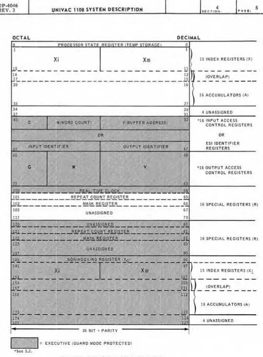
The 128 program-addressable control registers are grouped to provide multiple index registers, accumulators, input/output access control registers, and special registers (see Figure 4-1).
The control registers are 36-bit integrated-circuit registers, with a basic cycle time of 125 nanoseconds. Two parity bits are included with each control register.
Effective use of multiple accumulators and index registers for the development and use of constants, index values, and operands substantially improves performance. UNIVAC 1108 compilers, for example, perform significantly better through multiple register usage and can produce highly efficient code.
In the following descriptions only programmable registers are discussed. The Executive, th rough mo des establi sh ed by th e P rocesso r State Register, has excl usi ve use of th e duplicate set of control registers as well as the access control registers indicated by the shaded areas in Figure 4-1.
4.4.1. Index Registers
Control register locations 18 - 178 are Index Registers and have. the following format:
[
X.
35
MODIFIERINCREM~NT
OR DECREMENTXm
INDEX MODIFIER
18 17
a
The Xm portion of the index register is an 18-bit modifier to be added to the base operand address of the instruction. The Xi portion of the index word updates the Xm portion, after ba se operand address modification.
Index regi ster modification is specified by a 1 bit in the h field of the instruction, while indexing itself is specified by a nonzero value in the x field. Both functions take place within the basic iristruction execution cycle.
When ea scaded indirect a ddres si ng is used ina programme d op eration, full indexing capabilities are provided at each level. Indirect addressing replaces the x, h, i, and u portions of the instruction register, beginning with a new indexing cycle for each cascaded sequence. This process continues until the i field is zero.
UP-4046 Rev. 3
4
4
UNIVAC 1108 SYSTEM DESCRIPTION
SECTION: PAGE:4.4.2. Arithmetic Accumulators
Control register locations (14S - 33S) are arithmetic accumulators for programmed storage of arithmetic operands and results. The computation is performed in other registers
within the arithmetic section.
Depending upon the instruction, the accumulators are used to hold a variety of word formats. Double-precision instructions and a number of logical instructions reference two contiguous accumulators, that is, A and A
+
1. In arithmetic operations, A+
1 always holds the least significant part of an operand or result. Some instructions, such assingle precision floating-point operations, call on a one-word operand from main storage but produce a two-word result in the specified A and A
+
1 registers.4.4.3. A ccess Co ntro 1 Registers
Control register locations (40S - 77S) are Input and Output Access Control Regi sters (ACR's). They are guard mode protected and may be referenced only by the Executive. Form ats of the access control words are detailed in Section 5.
The word-by-word transmis$ion of data over an I/O channel is governed by the con-tents of the ACR's. Two ACR's, one for input and one fo·r output, are assigned to each of the sixteen channels. Input ACR' s (locations 40S ~ 57S) 'control input data transfers while output ACR's (locations 60S - 77S) govern the transmission of output data and function words.
When an input/ output operation is ini ti ated, the pro gramm ed acc ess control word (ACW) is loaded into the ACR corresponding to the channel associated with the specified peripheral unit.
4.4.4. R Registers
The sixteen controJ register locations (100S - 117S) are R registers. The fi rst three of these (RO, R1, R2) have specified ·functions and formats as described below. The remaining R registers are not specifically assigned; typically they are used as loop counters, transient registers, or storage for intermediate values or constants.
4.4.4.1. RO - Real Time Clock
UNASSIGNED CLOCK COUNT
This register is initially loaded by the program. The contents are then decrem ented once each 200 microseconds. A real-time clock interrupt occurs when the clock count goes through zero. Thus, if the clock is initially loaded with the value 5000
5
P AGE:
UP·4046
~
4REV. 3 UNIVAC 1108 SYSTEM DESCRIPTION SECTION:
---
,---~---~~~~----~---OCTAL DECIMAL
Xm
12
lL ____________________________
.l.5
36 BIT + PARITY
= EXECUTIVE (GUARD MODE PROTECTED) *See 5.2.
Figure 4-7. Control Register Address Assignments
15 INDEX REGISTERS (X)
(OVERLAP)
16 ACCUMULATORS (A)
4 UNASSIGN ED *16 INPUT ACCESS
CONTROL REGISTERS OR
ESI IDENTIFIER REGISTERS
*16 OUTRUT ACCESS CONTROL REGISTERS
16 SPECIAL REGISTERS (R)
16 SPECIAL REGISTERS (R)
15 INDEX REGISTERS (XL
(OVERLAP)
16 ACCUMULATORS (A)
UP - 4046 Rev. 3
4
UNIVAC 1108 SYSTEM DESCRIPTION SEC TION: P AGE:
4.4.4.2. R1 - Repeat Counter
UNASSIGNED REPEAT COUNT (k)
The repeat counter controls repeated operations such as Block Transfer and search instructions. To execute a repeated instruction k times, the repeat counter is loaded with k prior to the execution of the "instruction.
4.4.4.3. R2 - Mask Register
The mask register functions as a filter in determining which portions of words are to be tested in repeated masked search operations or in logical comparisons. (U) is compared to (A) only with respect to those positions which contain one's in the mask register. In repeated masked search operations, both the mask register and the repeat counter are loaded prior to executing the search command.
LS. ARITHMETIC SECTION
6
In the UNIVAC 1108 System the manipulation of data (addition, subtraction,multiplication; di vision, shiftin g) tak es place in the ari thm eti c section of the central p roc esso r. During the execution of an arithmetic instruction, storage registers within the arithmetic section itself are used for actual computation. The arithmetic section has the following characteristics:
• On fixed-point single precision instructions, the j designator selects all or a portion of one of the operands (half, third, quarter 0 r sixth word) for use in the arithmetic
operation.
• Special split-word arithmetic instructions provide for simultaneous addition or sub-traction of corresponding half or third words of the two operands.
• When a ~hift matrix is u sed, a m ultipo sition shift requires th e sam e tim e as a one place shifL Right and left shifts of single or double length operands can be speci-fied. Left shifting is logical (zeros are filled to the right) or circular (end-around)· Right shifts may be either logical, algebraic (sign bits are filled to the left), or circular.
• Sixteen arithmetic registers in the control register section, acting as sixteen accumulators, allow parallel and cumulative computation. Full double-precision floating point arithmetic is provided.
• When the results of arithmetic operations are in double-length form, they are au tom aticall y stored in consecutive control regi sters an dare available for retrieval as doubl e-Iength results.
4
7Rev. 3 UNIVAC 1108 SYSTEM DESCRIPTION SECTION: P AGE:
UP·A046
~
---
---~---~---4.5.1. The Adder
The adder in the 1108 Processor is a ones complement subtractive adder for 36-bit or 72-bit operations. F or purposes 0 f analysi s and debugging, the pro g ramm er may
manually simulate the computer operation by simple binary or octal addition.
Two special internal designators associated with the arithmetic adder are the
overflow designator and the carry designator. The fixed-point addition and subtraction instructions, single and double precision, are the only instructions which affect these two designators.
Before the execution of one of these instructions both designators are cleared. The overflow designator is set upon generation of a significant bit in the sign position. Thus a positive result from two negative quantities or a negative result from two posi ti ve quantities sets the overflow designator. The carry designator is set when-ever an end-around carry is generated.
After the instruction has been performed, the designators remain either set or clear until another of the designated arithmetic instructions is initiated. Both designators are set in tim e to be tested immedi ately afte r th e sp ecifi ed instruction has been executed.
When an interrupt occurs, the hardware stores the settings of the carry and overflow designators in th e p roc essorState Re gi ster (s ee 4.6.1) and con t rol pas ses to the Ex ecuti ve sys tern. Thi s info rm ation is autom atically returned to the desi gna to rs when the Executive returns control to the interrupted program.
4.5.2. Arithmetic Accumulators
The si xteen arithmetic accum ulato rs can be addres sed directly by th e pro gramm er and are available for storing operands and results of arithmetic computations. These arithmetic accumulators should not be confused with the nonaddressable transient registers contained within the arithmetic section itself used in actual computation.
With the Add To X and Add Negative To X instructions, the index registers also act as accumulators in the same manner as the arithmetic registers.
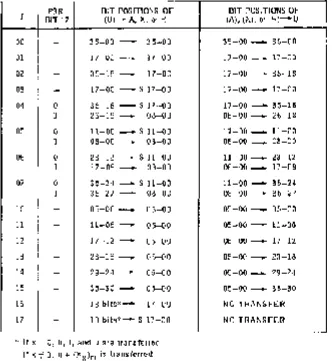
4.5.3. Partial-Word Transfers
To minim iz e sh ifti ng an d m askin g and to allow com pu tation based on sel ected portions of words, the 1108 System permits the transfer of partial words into and out of the arithmetic section in a varying pattern (see Figure 4-2).
uP- 4046
Rev. 3
UNIVAC 1108 SYSTEM DESCRIPTION
PSR BIT POSITIONS OF J BIT 17 (U)-A, X, or R
00
-
35-00-
35-0001
-
17-00-
17-0002
-
35-18-
17-0003 - 17-00 - S 17-00
04 0 35-18 - S 17-00
1 26-18 - 08-00
05 0 11-00 - S 11-00
1 08-00 _ 08-00
06 0 23-12 - S 11-00
1 17-09 - 08-00
07 0 35-24 - S 11-00
1 35-27 - 08-00
10 - 05-00 _ 05-00
11 - 11-06
-
05-0012
-
17-12-
05-0013 - 23-18 - 05-00
14
-
29-24 - 05-0015
-
35-30 - 05-0016 - 18 bits*- 17-00
17
-
18 bits*- S 17-00* I f x = 0, h, i, and u are t ran s fe r red If x =I 0, u + (Xx)m is transferred
4
SECTION:
BIT POSITIONS OF (A), (X), or (R)-U
35-00 - 35-00
17-00 _ 17-00
17 -00 - 35-18
17-00 - 17-00
17-00 - 35-18
08-00 _ 26-18
11-00 _ 11-00
08-00 _ 08-00
11-00 _ 23-12
08-00 _ 17-09
11-00 - 35-24
08-00 - 35-27
05-00 - 05-00
05-00 - 11-06
05-00 - 17-12
05-00 - 23-18
05-00 _ 29-24
05-00 - 35-30
NO TRANSFER NO TRANSFER
S
=
Sign Extension, where the sign is that of the j-determined final contents of A.Figure 4-2. i-Determined Partial-Word Operation
4.5.4. Split-Word Arithmetic
P AGE:
The System can perform addition and subtraction of half-words or third- words simultaneously. The right hal ves of two operands, for example, are added and the sum is stored in the right half of the selected accumulator. At the same time, the left halves of the same two operands are added and the result is stored in the left half of the same accumulator. There is no carry interaction between the halves. The same holds true for thirds of words. Each partial word operates as an inde-pendent arithmetic register with its own end-around carry.
4.5.5. Shifting
The System can perform both single-length shifting (36 bits) or double-length shifting (72 bits), treating the latter as if operating with a single 72-bit register. A high speed shift matrix makes execution time independent of the number of places in-volved in the shift, which means that an operand can be shifted from 0 to 72 positions in one main storage cycle time.
4
9
SECTION: F' AGE:
UP~4046
~
Rev. 3
UNIVAC 1108 SYSTEM DESCRIPTION
---
,----~.~---~---~---~---~---Six types of shift operations are provided:
I Right Circular - bits shifted out at the right reappear at the left. • Left Circular - bits shifted out at the left reappear at the right.
• Right Logical - zeros replace bits shifted out of the most significant positions. • Left Logical - zeros replace bits shifted out of the least significant positions.
• Right Algebraic - sign bits replace bits shifted out of the most significant positions.
• Scale-Factor Shift - a single or double accumulator left shift which positions the word and simultaneously counts the number of shifts required until
(A 35 ) j:. (A34)·
4.5.6. Double-Precision Fixed Point Arithmetic
The System provides 72-bit, double-precision fixed point addition and subtraction. Operands are processed as if they occupied a single 72-bit register. Bit 71, the high order bit, is the sign bit.
In addition, several arithmetic instructions produce two-word results. With fixed point multiplication, a double-length product is stored in two arithmetic registers for integer and fractional operations. Integer and fractional division is performed upon a double-length dividend with the quotient retained in A and the remainder retained in A
+
1.4.5.7. Floating-Point Arithmetic
13~134
The System is equipped with an extensive hardware repertoire of floating-point instructions. If the arithmetic is single precision, the range is from 1038 to 10-38 with eight-digit precision. The word formats are given below.
Source 0 perund Fa rm at
EXPONENT
2L
FIXED POINT PARTResult Format
Il4
EXPONENT2L
FIXED POINT PARTWORD 1
~
EXPONENT2L
4
FIXED POINT PART
UP-4046 Rev. 3
~
G N 35 34
4
UNIVAC
1108 SYSTEM
DESCRIPTION SECTION:In a single-precision floating point operation word 1 is the more significant portion of the result. Word
2
contains the less significant portion. Mathematical error tracing can determine how much accuracy is being lost in calculations using this format. The least significant word is displaced 27 bits to the right of the binary point in the significant word. Hence, its exponent is al ways adjusted by -27. The two-word result of this single-precision operation is stored in two contiguous Arithmetic Registers.If the arithmetic is double precision, the range is from 10 307 to 10-308 with 18-digit precision. The values are expressed in two adjacent words, as shown in the following format.
Source and Result Format
)
EXPONENT
}
24 23
P AGE:
Full double-precision operations do not require a repeated sign and exponent in the 36 least significant bits.
In any of the floating-point formats the exponent can assume a range of values as follows:
Single precision: (8 bits) Double precision: (11 bits)
000-255
0000-2047
To express negative exponents, the hardware biases or floats the exponent on a midval ue. The sign bit of the floating-point word applies to the fixed-point part. The true and biased ranges of the exponent are as follows:
True Biased
Single precision: -12810 to +12710
o -
25510 Double precision: -1024 10 to +102310o -
204710A positive fixed-point part is normally assumed to be in range Y2 to 1. Such a value places a 1 bit in the most significant bit position. When this condition exists, the floating-point number is said to be normalized. A negative fixed-point part causes the entire floating-point word to be complemented, and a 0 appears in this posi