nae2007
The 5th International Conference on Numerical Analysis in Engineering
Static and Dynamic Problem
3 - 24
EXACT AND NUMERICAL SOLUTION OF
PURE TORSION
SHAFT
Ismail Thamrin and Hasan Basri
Department of Mechanical Engineering, Sriwijaya University
Kampus Unsri Inderalaya Jalan Raya Palembang-Prabumulih km.32 Inderalaya, Ogan Ilir Phone : (0711-580272)
E-mail: [email protected] ; [email protected]; [email protected]
Abstract
Exact analysis on complex structure often meets with problems since it needs a long complicated mathematical defferential solution. Instead of using this, another method called finite element method is introduced i.e. a numerical solution undergone by discretion structure of infinite in to finite element that continuously build mesh. Application of pure torsion on prismatic can be done to a certain part of cross sectional of shaft loaded by torque subject to couple transmission, therefore in its manufacturing and fabrication process, stress analysis is significant factor to take into consideration since one of shaft failures may be caused by excessive stress distribution on some area. The comparison of exact and numeric solution ( FEM ) on pure torsion shaft which holds torsion 2,5 Nm and whose dimension is major axis ( a ) and minor axis ( b ) is 1,2375 x 10⁻² m and 1,05 x 10⁻² m respectively, and prismatic length ( l ) = 9,845 x 10-2 m. Mechanical Properties i.e. shear modulus ( G ), Young modulus ( E ), yield point ( Yield ), each 8,02 x 10¹¹ Pa ; 2,07 x 10 11 Pa ; 4,14 x 10⁸Pa, respectively and Poisson and Hardening ratio ; ( = 0,29 ) and 800. Exact and Finite Element analysis have the same characteristic of maximum shear stress on boundary cross sectional that is closest from centre point of torsion (Gravity Centre). Comparative exact result to FEM has divergent deviation to maximum shear stress
Keywords: FEM, Pure torsion shaft, Exact solution, Fast
1.
Introduction
Exact analysis on complex structure often meets with problems since it needs a long complicated mathematical deferential solution. Instead of using this, another method called finite element method is introduced i.e. a numerical solution undergone by discretion structure of infinite in to finite element that continuously build mesh.
Application of pure torsion on prismatic can be done to a certain part of cross sectional of shaft loaded by torque subject to couple transmission, therefore in its manufacturing and fabrication process, stress analysis is significant factor to take into consideration
since one of shaft failures may be caused by excessive stress distribution on some area.
2. Elasticity of Torsion
Elasticity of single crystal is unequal in the different direction and random. To achieve a usable homogenous assumption at high accuration, the elasticity of geometric element to be average property of crystal and when the direction of the single crystal is different, the material can be considered as isotropic material.
nae2007
The 5th International Conference on Numerical Analysis in Engineering
Static and Dynamic Problem
3 - 25
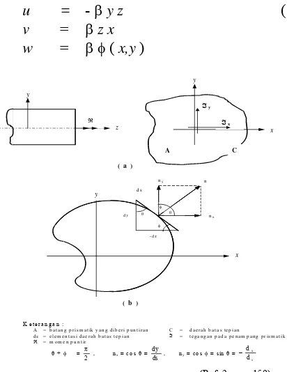
approach by A.J.C. Barre Venant – Saint (figure 1).
Eulerian and Lagrangian illustration of linearization characteristic of strained component to displacement value ( ) and
Linearization of Lagrangian rotation tensor on rotation component is
i,j =
Considering stress and elasticity constant of material on pure torque is determined by strain component, hence only influential shear stress existed perpendicular to prismatic axis. This is possible in consideration of both strain to displacement value and occurred shear strain can be neglected
xx = yy = zz = xy = 0
Without considering weight force aspect of prismatic and then eliminating stress function on element equilibrium hence boundary condition on cross section area ( A ) and cross sectional boundary ( C ).
2 = 0 (4)
n . =
dn
d
Relationship between twisting moment and twist angle is
=
x y
dAA yz xz
(5)= D
3. Exact Analysis
Based on the definition of stress function with complex variable.
F ( z ) = + i
(6) Hence shear strain becomesxz =
nae2007
The 5th International Conference on Numerical Analysis in Engineering
Static and Dynamic Problem
3 - 26
Hence boundary condition of cross sectional area ( A ) and boundary of cross sectional (C)
2 = -2 (9)
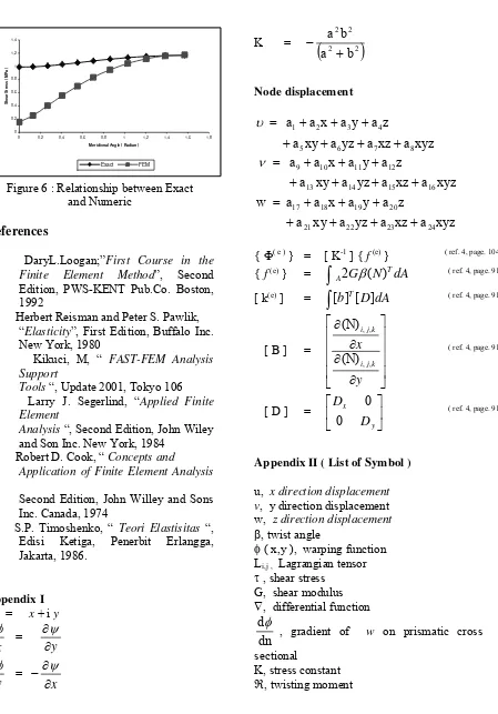
= K
Stiffness torsion of elliptical cross sectional
D = dA
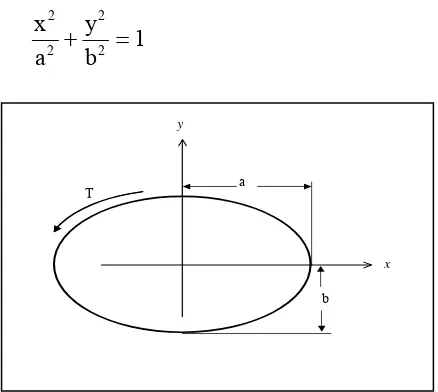
While for stress analysis of elliptical prismatic ( figure 2 ) with boundary cross sectional area
1
Fig. 2 : Cross Sectional of Elliptical Prismatic
Stress function on elliptical cross sectional boundary according to Ludwig Pradath
c =
Elliptical cross sectional stiffness torsion
D = 2 2
Hence it is found that coordinated tangential stress on cross sectional boundary (C) is the result of the Pythagoras sum of both occurred shear stresses in square root, and its resultant angle is as equal as the result of both shear stresses
=
4. FEM Analysis
Finite element technique involves element-modeling discretion, which is defined through a displacement function of each node.
F
k
DModeling used is rectangular trilinear element ( fig. 3 ) which has 27 nodes. AS the result, when the pure torsion is occurred to the prismatic, then the out coming strain and stiffness matrix are
{ ( e ) } = [ N1 N2 . . . Nn ] { ( e ) }
Next, we can determine the possible out coming stress by
{ (e) } = [ B ] { (e) }
Finite element analysis is supported by FAST Software and structure analysis, by FEM 3dat.C. The boundary conditions of prismatic, both are clamped and are torque. This loading
T
a
b
nae2007
The 5th International Conference on Numerical Analysis in Engineering
Static and Dynamic Problem
3 - 27
characteristic torsion is transformed into concentrated forces; where each has equal torsion on each node, therefore result desirable resultant torsion (figure 3)
Fig. 3: Boundary Condition of Elliptical Prismatic
Table 1 is the comparison of exact and numeric solution (FEM) on elliptical prismatic which holds torsion 2,5 Nm and whose dimension is major axis (a) and minor axis (b) : 1,2375 x 10⁻² m and 1,05 x 10⁻² m
respectively, and prismatic length (l) = 9,845 x 10-2 m. Mechanical Properties i.e. shear
modulus (G), Young modulus (E), yield point
(Yield), each 8,02 x 10¹¹ Pa ; 2,07 x 10 11 Pa ;
4,14 x 10⁸Pa, respectively and Poisson and Hardening ratio ; ( = 0,29) and 800.
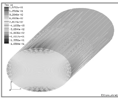
Fig. 4 : Shear Stress of yz Direction (yz )
Fig. 5: Shear Stress of xz Direction (xz )
Table 1 Comparison of Exact and Finite Element result
MERIDIONAL
ANGLE( o )
SHEAR STRESS ( MPa )
EXACT FEM
yz xy
0,000000 0,989787 -0,020708 0,1554892 0,156862
7,469698 0,993678 -0,202317 0,1575184 0,256407
15,413007 1,008002 -0,378269 0,1450308 0,405119
23,380027 1,028703 -0,544416 0,1193671 0,557348
31,652126 1,054208 -0,696980 0,0830607 0,701912
40,314084 1,081777 -0,832578 0,0393264 0,833506
49,427157 1,108660 -0,948171 -0,0082670 0,948207
59,014652 1,132364 -1,041099 -0,0559881 1,042600
69,046075 1,150829 -1,109095 -0,0999039 1,113590
79,426391 1,162527 -1,150319 -0,1357099 1,158300
90,000000 1,166535 -1,163527 -0,1589426 1,174330
Appendix III shows the example of exact solution and appendix IV numeric of Finite Element analysis supported by FAST software.
Conclusions
nae2007
The 5th International Conference on Numerical Analysis in Engineering
Static and Dynamic Problem
3 - 28
Meridional Angle ( Radian )
S
Exact FEM
Figure 6 : Relationship between Exact and Numeric
References
[1] DaryL.Loogan;”First Course in the Finite Element Method”, Second Edition, PWS-KENT Pub.Co. Boston, 1992
[2] Herbert Reisman and Peter S. Pawlik, “Elasticity”, First Edition, Buffalo Inc. New York, 1980
[3] Kikuci, M, “ FAST-FEM Analysis Support
Tools “, Update 2001, Tokyo 106 [4] Larry J. Segerlind, “Applied Finite
Element
Analysis “, Second Edition, John Wiley and Son Inc. New York, 1984
[5] Robert D. Cook, “ Concepts and
Application of Finite Element Analysis
“,
Second Edition, John Willey and Sons Inc. Canada, 1974
[6] S.P. Timoshenko, “ Teori Elastisitas “, Edisi Ketiga, Penerbit Erlangga, Jakarta, 1986.
Appendix I z = x + i y
Node displacement
xyz
u, x direction displacement v, y direction displacement w, z direction displacement
, twist angle
( x,y ), warping function
Li,j , Lagrangian tensor
, shear stress G, shear modulus , differential function
dn
d
, gradient of w on prismatic cross
sectional
nae2007
The 5th International Conference on Numerical Analysis in Engineering
Static and Dynamic Problem
3 - 29
D, torsion stiffness of prismatic cross sectional
a, major axes
Appendix III (Example of exact analysis)