Czeslaw T. Kowalski, Robert Wierzbicki, Marcin Wolkiewicz
Stator and Rotor Faults Monitoring of the Inverter-Fed Induction
Motor Drive using State Estimators
DOI UDK IFAC 10.7305/automatika.54-3.167 681.5.09.015.44.03:621.313.33-253-226.1 2.1.4; 1.1
Original scientific paper
The paper deals with the application of the Extended Kalman Filter and the Extended Luenberger Observer algorithms for the stator and rotor fault detection of the induction motor fed by PWM inverter. The induction motor conditions are analyzed using estimated rotor and stator-winding resistance. Mathematical models of the extended state estimators are presented, in which the stator and rotor resistances are added as additional electromagnetic state variables. Experimental results for the inverter-fed induction motor, with shorted stator-turns and broken rotor bars, are presented and analysed.
Key words: induction machines, diagnostics, fault detection, Kalman filter, Luenberger observer
Nadgledanje statorskih i rotorskih pogrešaka asinkronog motora napajanog inverterom koriste´ci estima-tore stanja. Ovaj radi prouˇcava primjenu algoritama proširenog Kalmanovog filtra i proširenog Luenbergerovog observera za detekciju pogreške statora i rotora asinkronog motora napajanog PWM inverterom. Stanja asinkronog motora analizirana su korištenjem estimiranog otpora statorskih i rotorskih namota. Prikazani su matematiˇcki mod-eli proširenih estimatora stanja u kojima su otpori statora i rotora dodani kao dodatne varijable stanja. Prikazani su i analizirani eksperimentalni rezultati za asinkroni motor napajan inverterom s kratko spojenim statorskim namotima i prekinutim rotoskim polugama.
Kljuˇcne rijeˇci: asinkroni stroj, dijagnostika, detekcija pogreške, Kalmanov filtar, Luenbergerov observer
1 INTRODUCTION
Induction motor (IM) drives are widely used nowa-days in many industrial processes and thus problems of their maintenance and fault detection become more impor-tant. The failure of the motor can cause substantial finan-cial losses and even damage of the whole drive system. Needs of the analysis of an actual technical condition of IMs caused in the last years the great development of diag-nostic methods and techniques, which could be used in the fault detection of IMs drives [1], [2].
Stator and rotor faults are responsible respectively for 37% and 13% of the IM failures and, after the bearing faults, are the most frequent reasons of the IM damages. In monitoring and diagnosis of IM drives mostly the stator current and mechanical vibrations are used as diagnostic signals.
Due to simplicity of measurements, the stator current signals are more widely used for this purpose and thus dif-ferent analysis methods have been developed, based on detection of sidebands harmonics at certain frequencies. Such methods like Fast Fourier Transform (FFT), Short
Time Fourier Transform (STFT), the Wavelet Transform (WT) and the high order transformation (HOT) are more and more often applied [1]-[3].
In the case of IMs supplied from frequency inverters such analysis is much more complicated due to additional harmonics generated by the inverter supply, which overlaps with harmonics caused by the stator or rotor faults. There-fore, the usual techniques, based on spectral analysis of the stator current signal are not well adapted in adjustable speed motor drives and some authors have proposed the methods based on an on-line estimation of motor param-eters changes due to motor failures [4]. In normal opera-tion condiopera-tions, estimated parameters have nominal values, which change in the limited range (due to a temperature rise). If the motor fault occurs, these changes are growing or decreasing much faster, so the analysis of the estimated parameter changes enables the detection of the failure.
In this paper, the diagnostic technique of the stator and rotor faults of the inverter-supplied IM by on-line parame-ter identification is presented, using the Extended Kalman Filter algorithm (EKF) and Extended Luenberger Observer
(ELO). Analysis of the changes of the estimated rotor and stator resistances is used for fault detection of the PWM inverter-fed IM. The main goal of this paper is to show the practical digital realization the EKF and ELO algorithms in the fault detection task of the IM and to prove the earlier theoretical results presented in [5].
2 MATHEMATICAL MODEL OF THE INDUC-TION MOTOR
Using well-known simplifying assumptions, the IM mathematical model can be described by the space vector equations in the stationary (α−β) reference frame as in [5, 6].
– the state equation:
˙
x(t) =A(ωm)·x(t) +B·u(t) (1)
– the output equation:
y(t) =C·x(t) (2) where:
– the state vector (of electromagnetic state variables): x(t) = isα isβ ψrα ψrβ
T
(3) – the input and output vectors:
u(t) = usα usβ T (4) y(t) = isα isβ T (5) – the state matrix:
A(ωm) = a 0 b c 0 a −c b d 0 −e −ωmΩb 0 d ωmΩb −e (6)
– the inputBand outputCmatrices:
B= " Ω b σ·xs 0 0 0 0 Ωb σ·xs 0 0 #T (7) C= 1 0 0 0 0 1 0 0 (8) where: a=− 1 xsσ rsΩb− 1−σ xrσ rrΩb, b= krrrΩb xrxsσ c= ωmkrΩb xsσ , d= xM xr rrΩb, e= rrΩb xr , kr= xM xr
and:usα,usβ,isα,isβ,ψsα,ψsβ - coordinates of the
sta-tor voltage and current vecsta-tor, and the rosta-tor flux vecsta-tor, re-spectively,rs,rr,xs,xr,xM -stator and rotor resistances,
stator and rotor reactances, mutual reactance, respectively, σ- total leakage coefficient,ωm- rotor speed,Ωb-
refer-ence angular pulsation.
3 EXTENDED KALMAN FILTER ALGORITHM
In According to the Kalman filter theory [7], IM model (1)-(8), must be written in the discrete form:
xR(k+ 1) =AR(k)xR(k) +BR(k)uR(k) +w(k) yR(k) =CR(k)xR(k) +v(k) (9)
wherewandv are matrices of the process and measure-ment noises, and matrices AR,BR,CR and vector uR
are filled respectively with zeros in last rows or columns comparing to (6)-(8) and (4).
Estimation of state vector is realized in the following steps:
• step 1- the state vector predictorxˆR(k+1)in the step
(k+1) is calculated using inputu(k)and state vector
predictor in the previous stepˆxR(k):
ˆ
xR(k+ 1/k) =AR(ωm(k))·xˆR(k/k) +BR·u(k)
(10)
• step 2- the covariance matrix of the prediction error is estimated:
P(k+ 1/k) =FR(k)P(k)FR(k)T +Q(k) (11)
whereFR(k) = ∂f(xR∂x(k/kR(k/k),u)(k),k)|xR=ˆxR(k/k),
Q- the state noise covariance matrix,
• step 3 - the Kalman filter gain matrix is calculated using following equations:
K(k+ 1) =P(k+ 1/k)·CR(k+ 1)T· ·[CR(k+ 1)·P(k+ 1/k)·CR(k+ 1) +R]−1
(12) whereR- the output (measurement) noise covariance
matrix,
• step 4- the correction of the state vector estimate (ac-cording to the general form of Kalman filter model) is calculated:
ˆ
xR(k+ 1/k+ 1) = ˆxR(k+ 1/k) +K(k+ 1)· ·[y(k+ 1)−CR(k+ 1)·xˆR(k+ 1/k)]
• step 5- the filter covariance matrix of the state esti-mation error is updated:
P(k+ 1/k+ 1) = [I−K(k+ 1)·CR(k+ 1)]·
·P(k+ 1/k) (14)
• step 6- return to the first step.
The convergence and dynamical behavior of the Kalman filter algorithm depends strongly on the suitable chosen covariance matricesQandR[5].
Stator and rotor resistance are selected as additional state variables, so two new extended state vectors for stator and rotor fault diagnosis are defined as follows:
xsR(t) = isα isβ ψrα ψrβ rs T (15) xrR(t) = isα isβ ψsα ψsβ rr T (16) where: ψsα,ψsβ - components of the stator flux vector,
calculated based on the well-known algebraic equations, using stator current and rotor flux vector components.
4 EXTENEDED LUENBERGER OBSERVER AL-GORITHM
4.1 Rotor resistance estimation
For the estimation of the rotor winding resistance, the state vector (3) of the mathematical model (1)-(8) has been extended with this parameter as follows:
ˆ xrR= ˆ isα ˆisβ ψˆrα ψˆrβ rˆr T . (17) According to the Luenberger theory [7], [8] the ex-tended full-order state observer can be developed in the form: dxˆr R dt = ˆA r R(ˆxrR) ˆxrR+BRu+GrR(ˆis−is) (18)
where the input vector as in (4), and:
• the extended state matrix as in (19):,
ˆ ArR(ˆrr, ωm) = − 1 xsσrsΩb+ 1−σ xrσrˆrΩb 0 krˆrrΩb xrxsσ ωmkrΩb xsσ 0 0 − 1 xsσrsΩb+ 1−σ xrσˆrrΩb −ωmkrΩb xsσ krˆrrΩb xrxsσ 0 xm xrrˆrΩb 0 − ˆ rrΩb xr −ωmΩb 0 0 xm xrrˆrΩb ωmΩb − ˆ rrΩb xr 0 0 0 0 0 0 (19)
• the extended input matrix:
BR= " Ω b σ·xs 0 0 0 0 0 Ωb σ·xs 0 0 0 #T (20)
• the extended observer gain matrix:
GrR= g1 g2 g3 g4 kor ˆ ψrα−xmˆisα −g2 g1 −g4 g3 kor ˆ ψrβ−xmˆisβ T (21) where: g1=−(ko−1)( rs σxs + 1 σTr ), g2= (ko−1)ωm, g4=−c(ko−1)ωm, g3= (ko2−1)(−c( rs σxs +1−σ σTr ) +xm Tr )+ +c(ko−1)( rs σxs + 1 σTr ) ˆ
rr - estimated rotor resistance in the previous numerical
step,ko,kor - positive constants.
4.2 Stator resistance estimation
For the estimation of the stator winding resistance, the state vector of the mathematical model (1)-(8) has been extended with this parameter as follows:
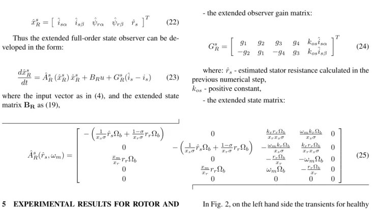
ˆ xs R= ˆ isα ˆisβ ψˆrα ψˆrβ rˆs T (22) Thus the extended full-order state observer can be de-veloped in the form:
dxˆsR dt = ˆA
s
R(ˆxsR) ˆxsR+BRu+GsR(ˆis−is) (23)
where the input vector as in (4), and the extended state matrixBRas (19),
- the extended observer gain matrix:
Gs R= g1 g2 g3 g4 kosˆisα −g2 g1 −g4 g3 kosˆisβ T (24) where:ˆrs- estimated stator resistance calculated in the
previous numerical step, kos- positive constant,
- the extended state matrix:
ˆ As R(ˆrs, ωm) = −x1sσˆrsΩb+ 1−σ xrσrrΩb 0 krrrΩb xrxsσ ωmkrΩb xsσ 0 0 − 1 xsσˆrsΩb+ 1−σ xrσrrΩb −ωmkrΩb xsσ krrrΩb xrxsσ 0 xm xrrrΩb 0 − rrΩb xr −ωmΩb 0 0 xm xrrrΩb ωmΩb − rrΩb xr 0 0 0 0 0 0 (25)
5 EXPERIMENTAL RESULTS FOR ROTOR AND STATOR FAULTS
5.1 General description of experimental benchmark
In order to check the theoretical backgrounds and the possibilities of the EKF and ELO application for the on-line detection of stator and rotor fault of IM, experimental tests were performed in the Direct Field Oriented (DFOC) structure, presented in Fig. 1a.
Laboratory tests were realized in the laboratory set-up, for the 1.5kW IM with a few specially prepared rotors and a stator winding. Tested motor has 412 turns per stator phase-winding and 28 bars in rotor. In experimental tests different winding failures were modeled physically (with exchangeable rotors having different numbers of damaged bars: health and from 1 to 8 broken rotor bars, as well as for different number of shorted turns in the stator winding: 1, 2, 4, 8, 10, and 16).
The IM was supplied from the frequency converter, with Space Vector Modulator. The vector control struc-ture DFOC, together with the EKF or ELO and residuum determination were realized using digital signal processor DS1104 of dSPACE. The whole application has been writ-ten in C language. The general scheme of the laboratory set-up is given in Fig. 1b.
5.2 Rotor fault detection
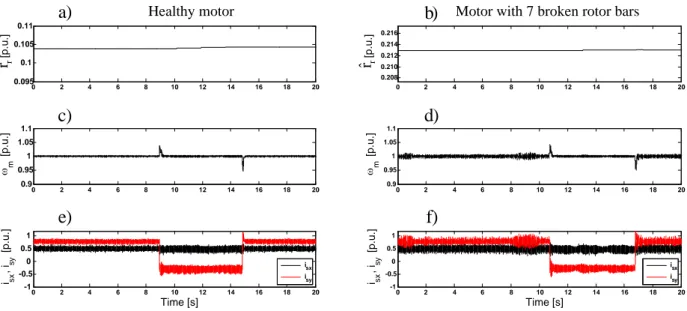
The examples of the experimental drive system oper-ation with on-line estimoper-ation of rotor winding resistance using EKF and ELO are demonstrated in Fig. 2 and Fig. 3, for speed reference and load torque changes, respectively.
In Fig. 2, on the left hand side the transients for healthy motor are presented, and on the right hand side the simi-lar transients for the motor with 7 broken rotor bars are
IM TG iABC uABC S V M SA SB SC xy PI PI PI usxr isyr s r PI r rr Rotor flux estimator isxr usyr DFOC Diagnosis/ Decision ALARM ABC
Extended Kalman Filter or Extended Luenberger Observer xy us us us us m m us us m isis isis isis isy isx uD usr usr Residuum determination r r s r r rN r r r ^ sN r s ^ a) dSpace DS1104 Induction motor DC Motor (Load Machine) En Control UDC a b c ISA ISB wm
Fig. 1. Schematic diagrams of the experimental bench-mark: a) structure of the DFOC drive system with on-line diagnosis of winding faults; b) laboratory set-up
0.092 0.094 0.096 0.098 0.1 [ p .u .] 0 0.5 1 m [ p .u .] -1 -0.5 0 0.5 1 Time [s] isx , isy [ p .u .] isx isy Healthy motor
a)
c)
e)
0 5 10 15 20 25 30 35 0 5 10 15 20 25 30 35 0 5 10 15 20 25 30 35 40 40 40 0 5 10 15 20 25 30 0.144 0.146 0.148 0.150 0.152 [ p .u .] 0 5 10 15 20 25 30 0 0.5 1 m [ p .u .] 0 5 10 15 20 25 30 -1 -0.5 0 0.5 1 Time [s] isx , isy [ p .u .] isx isyMotor with 7 broken rotor bars
b)
d)
f)
r
rˆ
rˆ
rFig. 2. Experimental transients of estimated rotor resistance under changes of reference speed: estimated rotor resistance (a,b), motor speed (c,d) and stator current vector components x-y (e,f) for the EKF used as state estimator
0 2 4 6 8 10 12 14 16 18 20 0.095 0.1 0.105 0.11 [ p .u .] 0 2 4 6 8 10 12 14 16 18 20 0.9 0.95 1 1.05 1.1 m [ p .u .] 0 2 4 6 8 10 12 14 16 18 20 -1 -0.5 0 0.5 1 Time [s] isx , isy [ p .u .] isx isy Healthy motor
a)
c)
e)
0 2 4 6 8 10 12 14 16 18 20 0.208 0.210 0.212 0.214 0.216 [ p .u .] 0 2 4 6 8 10 12 14 16 18 20 0.9 0.95 1 1.05 1.1 m [ p .u .] 0 2 4 6 8 10 12 14 16 18 20 -1 -0.5 0 0.5 1 Time [s] isx , isy [ p .u .] isx isy Motor with 7 broken rotor barsb)
d)
f)
r
rˆ
rˆ
rFig. 3. Experimental transients of estimated rotor resistance under load torque changes: estimated rotor resistance (a,b), motor speed (c,d) and stator current vector components x-y (e,f) for the ELO used as state estimator Stator fault detection
shown, when EKF was used. The reference speed has been changed slowly from nominal to zero value and vice versa, and next from nominal to 50%, as can be seen in Fig. 2b. Change of the rotor speed in such a wide range causes very small changes of the rotor resistance, which have no influ-ence on the fault detection of the rotor. As can be seen, estimated rotor resistance reaches much bigger values in a case of faulted rotor (Fig. 2b) than for healthy rotor case
(Fig. 2a). Similar results can be obtained when ELO is used for rotor resistance estimation.
In Fig. 3 the changes of estimated rotor resistance un-der constant speed and changeable load torque are demon-strated, when ELO was used. The driven motor is nom-inally loaded, except of the time period t = (9÷15)s, when load torque is switched-off. Similarly, as for EKF based fault detector, ELO algorithm is not sensitive to step
changes of the load torque and estimates the rotor resis-tance properly as well for healthy (Fig. 3a,c,e) as for the faulted motor (Fig. 3b,d,f). The estimated rotor resistance for the faulted rotor case (Fig. 3b) is much bigger than for the healthy rotor (Fig. 3a), similarly as for the EKF detec-tor.
5.3 Stator fault detection
The experimental tests were done for the healthy motor and for the motor with different number of shorted turns in the one phase of the stator winding. In the following figures examples of results obtained for the EKF and next for the ELO are presented. These both fault detectors op-erate independly on the vector control structure and are re-sponsible only for the reconstruction of the stator or rotor resistance changes.
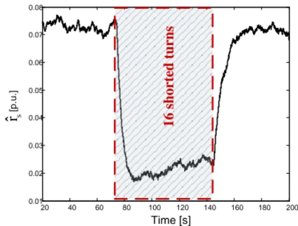
In Fig. 4 and Fig. 5 the results of the stator resis-tance estimation using EKF are demonstrated, in case of 16 shorted turns of the stator winding, for nominal load torque and nominal reference speed values. The fault was “activated” by realization of 16 short circuit turns in the real motor at the time t=75s, and “removed” at the time t=145s.
It can be seen that for the stator winding fault (16 shorted turns, which is around 4 % of total turns num-ber), the stator winding resistance decreases over 30%. The range of the stator resistance changes due to the turns’ short circuit is much smaller in the closed loop drive sys-tem than in open-loop (e.g.U/f=const strategy) [5]. How-ever it should be noticed, that the sensitivity of the EKF based method is from 6 shorted turns. Moreover, the stator resistance estimation using EKF requires long computation time (6-7s), what is not suitable for the stator fault detec-tion, as so long “decision time” can cause the permanent damage of the stator winding due to an avalanche charac-ter of this fault.
The similar tests were realized for the ELO used as the stator resistance estimator under healthy and faulted condi-tion of the IM operating in the close-loop vector structure. In Fig. 6 and Fig. 7 exemplary results of such tests are presented, for different number of shorted stator winding turns, for nominal load torque and reference speed. The conducted tests prove that in a case of ELO the on-line detection of the stator fault is possible even for a single shorted turn, which is big advantage of the proposed ap-proach, in contrary to the EKF application.
The fault indicator is proposed for the evaluation of fault detection effectiveness. In a case of the rotor and stator damage this indicator takes the following forms, re-spectively: δ rr= ˆ rr−rrN rrN 100% (26) 20 40 60 80 100 120 140 160 180 200 0.01 0.02 0.03 0.04 0.05 0.06 0.07 0.08 1 6 s h o rt ed t u rn s s rˆ [p .u .] Time [s]
Fig. 4. Experimental transients of the estimated stator re-sistance using EKF in a case of 16 shorted turns, for
nom-inal torque and reference speedωmz= 1[p. u.]
0.9 1 1.1 m [ p .u .] -2 -1 0 1 2 is , is [ p .u .] is is 30 60 90 120 150 180 210 240 -1 0 1 2 Time [s] isx , isy [ p .u .] isx isy 1 6 s h o rt ed t u rn s a) b) c) 30 60 90 120 150 180 210 240 30 60 90 120 150 180 210 240
Fig. 5. Experimental transients of the motor speed (a) and components of the stator current vector in a case of 16 shorted turns, for nominal torque and reference speed
ωmr= 1[p. u.] (EKF) δ rs= ˆrsr−sNrsN 100% (27)
wherersN,rrN - nominal values of stator and rotor
resis-tances.
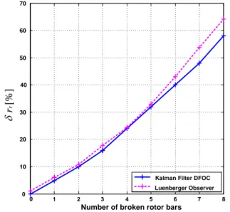
Comparison of the results obtained for EKF and ELO, in a case of rotor fault detection, is shown in Fig. 8.
The percentage rotor fault indicator increases with the increasing fault level for both tested estimation algorithms. It should be noticed that this indicator takes little bigger values for ELO than for EKF, starting from 5 broken rotor
0 10 20 30 40 50 60 0.02 0.03 0.04 0.05 0.06 0.07 0.08 Time [s] 4 s h o rt ed t u rn s 1 s h o rt ed t u rn 2 s h o rt ed t u rn s 8 s h o rt ed t u rn s 0.10 s
r
ˆ
[p .u .]Fig. 6. Experimental transients of the estimated stator re-sistance using ELO in a case of different number of shorted
turns, for nominal torque and reference speedωmz=1[p.u.]
0.9 1 1.1 m [ p .u .] -2 -1 0 1 2 is , is [ p .u .] is is 0 10 20 30 40 50 60 -1 0 1 2 Time [s] isx , isy [ p .u .] isx isy 1 s h o rt ed t u rn 2 s h o rt ed t u rn s 4 s h o rt ed t u rn s 8 s h o rt ed t u rn s b) c) 0 10 20 30 40 50 60 0 10 20 30 40 50 60 a)
Fig. 7. Experimental transients of the motor speed (a) and components of the stator current vector in a case of differ-ent number of shorted turns, for nominal torque and
refer-ence speedωmz = 1[p. u.] (ELO)
bars. Thus it can be said that both estimators, EKF and ELO indicate the rotor fault level with similar accuracy.
Comparison of the results obtained for EKF and ELO in a case of stator fault detection is presented in Fig. 9.
For the stator winding failure the proposed percentage fault indicator (27) increases with the increasing fault level for both tested estimation algorithms. Lower sensitivity to the fault occurrence can be observed for the EKF algo-rithm. Significantly better results were obtained for ELO algorithm, and very small fault level – 1 or 2 shorted turns,
0 1 2 3 4 5 6 7 8 0 10 20 30 40 50 60 70
Number of broken rotor bars
Kalman Filter DFOC Luenberger Observer
[%]
r
r
Fig. 8. The rotor fault indicator versus number of broken rotor bars 0 1 2 3 4 5 6 7 8 9 10 0 10 20 30 40 50 60 70 80 90 100
Number of shorted turns
Kalman Filter DFOC Luenberger Observer
[%]
s
r
Fig. 9. The stator fault indicator versus number of shorten turns of stator winding
can be detected easily with this algorithm (see also Fig. 7). Moreover, the calculation time for ELO is very short and fault indicator results are obtained on-line, in a real time.
6 CONCLUSION
The experimental tests proved the correctness of used theoretical models of the Extended Kalman Filter and the Extended Luenberger Observer, and demonstrated that the applied approach is suitable to the stator and rotor faults
detection of the inverter-fed induction motor.
Presented results show that both estimators present similar accuracy in case of the rotor faults, however the ELO algorithm is much simpler in practical realization and requires much less computational time.
In case of stator winding short circuits, the EKF presents smaller sensitivity to changeable number of shorten turns, especially in the incipient stator fault, com-pared to ELO. Moreover, in on-line diagnostics, it requires much more computational time, thus very fast digital pro-cessor is required.
The application of the EKF and ELO in the diagnostics based on mathematical modeling creates alternative to the classical, direct detection methods of the IM faults, based on the spectra analysis of the stator current and mechanical vibrations.
ACKNOWLEDGMENT
This research work was partly supported by the Na-tional Science Centre, Poland, under Grant NN510 637340 (2011-2013).
REFERENCES
[1] S. Bachir, S. Tani, J.-C. Trigeassou, G. Champenois, “Di-agnosis by parameter estimation of stator and rotor faults occurring in induction machines”, IEEE Trans. Ind. Elec-tronics, vol. 53, no. 3, pp. 963-973, 2006.
[2] A.Bellini, F. Filippetti, C. Tassoni, G.A. Capolino, “Ad-vances in Diagnostic Techniques for Induction Machines”, IEEE Trans. Ind. Electron., vol.55, no.12, pp. 4109-4126, Dec. 2008
[3] C.H. De Angelo, G.R. Bossio, S.J. Giaccone, M.I. Valla, J.A. Solsona, G.O. Garcia, “On-line Model-Based Stator-Fault Detection and Identification in Induction Motors”, IEEE Trans. Ind. Electron., vol.56, no.11, pp. 4671-4680, Nov. 2009
[4] M. Nait Said, M. Benbouzid, A. Benchaib, “Detection of Broken Bars in Induction Motors Using an Extended Kalman Filter for Rotor Resistance Sensorless Estimation”, IEEE Trans. Energy Conversion, vol. 15, no. 1, pp. 66-70, March 2000.
[5] C. T. Kowalski, R. Wierzbicki, “Application of the extended Kalman filter for rotor and stator fault detection of the in-duction motor”, Poznan Univ. Tech. Acad. Journal – El. En-gineering, vol. 55, pp.154-157, 2007
[6] C. T. Kowalski, T. Orlowska-Kowalska, R. Wierzbicki, “Application of the State Estimators for Stator and Ro-tor Fault MoniRo-toring of the Inverter-Fed Induction MoRo-tor Drive”, 17th Int. Conf. on El. Drives and Power Electronics EDPE’2011, Slovak Rep., 2011, on CD
[7] T. Orlowska–Kowalska, “Sensorless induction motor drives”, Wroclaw University of Technology Press, Wro-claw, Poland, 2003 (in Polish)
[8] H. Kubota, K. Matsuse, and T. Nakano, “DSP-based speed adaptive flux observer of induction motor”, IEEE Trans. Ind. Appl., vol. 29, np.2, pp.344-348, March/Apr., 1993
Czeslaw T. Kowalskireceived his scientific
de-grees from Wroclaw University of Technology, Wroclaw, Poland, in 1971, 1983, 2006, respec-tively. He has the Professor position at Electri-cal Engineering Faculty of Wroclaw University of Technology, in the Electrical Drives, Mecha-tronics and Industrial Automation Chair of the Institute of Electrical Machines, Drives and Mea-surements. He is author and co-author of more than 150 journal papers and conference proceed-ings, two textbooks, one book. His field of interest is mathematical mod-eling and microprocessor control of electrical drives and power convert-ers, monitoring and diagnosis of the electrical drives using state observers and neural networks.
Robert Wierzbickireceived the MSc and PhD
degrees from the Electrical Engineering Faculty, Wroclaw University of Technology, Wroclaw, Poland, in 2006 and 2011, respectively. He is an author and co-author of close to 20 scientific papers. His main fields of interest are the induc-tion motor drive control and state variable estima-tion, and its application for diagnostic problems of AC electrical drives. Currently he is employed in Whirpool Poland in Wroclaw.
Marcin Wolkiewiczreceived the MSc and PhD
degrees from the Electrical Engineering Faculty, Wroclaw University of Technology, Wroclaw, Poland, in 2007 and 2012, respectively. He has the Assistant Professor position at Electri-cal Engineering Faculty of Wroclaw University of Technology, in the Electrical Drives, Mecha-tronics and Industrial Automation Chair of the Institute of Electrical Machines, Drives and Mea-surements. He is an author and co-author of close to 30 scientific papers. His main fields of interest is monitoring and diagnosis of the electrical drives using signal analysis including advanced methods and transforms.
AUTHORS’ ADDRESSES
Prof. Czeslaw T. Kowalski, Ph.D., D.Sc. Wroclaw University of Technology
Institute of Electrical Machines, Drives and Measurements ul. Smoluchowskiego 19, Wroclaw 50-372, Poland
email: czeslaw.t.kowalski@pwr.wroc.pl Robert Wierzbicki, Ph.D.
Whirpool, Wroclaw, Poland
email: robert.wierzbicki@pwr.wroc.pl Marcin Wolkiewicz , Ph.D.
Wroclaw University of Technology
Institute of Electrical Machines, Drives and Measurements ul. Smoluchowskiego 19, Wroclaw 50-372, Poland
email: marcin.wolkiewicz @ pwr.wroc.pl
Received: 2012-01-15 Accepted: 2013-03-28