Document Title Document Version
D2.1.1 Data Acquisition Specification 1 0.9
Project Number Project Acronym Project Title
FP7-2011-7-287661 GAMBAS Generic Adaptive Middleware for Behavior-driven Autonomous Services
Contract Delivery Date Actual Delivery Date Deliverable Type Deliverable Access
M8 September 30th, 2012 R (Report) PU (Public)
Document Author or Reviewer Organization Work Package
Umer Iqbal UDE WP2
Gregor Schiele NUIG WP2
Marcus Handte UDE WP2
Michael Mende SC WP2
Abstract
0.2 NUIG Added a brief description of the SDS interface. 0.3 UDE Added text for Section 2, Section 3 and Section 5. 0.4 UDE Updated Section 4 and Section 5.
0.5 UDE Updated figures for the sections on tool support. 0.6 NUIG Feedback on Sections 1 to 4.
0.7 UDE Added additional clarifications and refinements based on NUIG feedback. 0.8 SC Added description of components.
List of Figures
Figure 1 – Data Acquisition Framework Overview ... 3
Figure 2 – Component System Overview ... 4
Figure 3 – Speech Detection Configuration Example ... 5
Figure 4 – Component System Structure ... 7
Figure 5 – Component System Tool Support... 8
Figure 6 – Activation System Overview ... 9
Figure 7 – Examples of Activation System States ... 11
Figure 8 – Example for Rule-based Transitions between States ... 11
Figure 9 – Activation System Structure ... 13
Figure 10 – Example Mapping of State Machines to Components ... 13
Figure 11 – Example for Active Graph Structures in Folded Configuration ... 14
Figure 12 – Activation System Tool Support ... 15
Figure 13 – Context Recognition Components Overview ... 16
1
Introduction
This deliverable contains the description about the adaptive data acquisition framework as part of the WP2 specification. The description includes discussions on the system architecture for the framework, including the component system for developing context recognition applications and the activation system for enabling automatic, state-based activation of different configurations. The document also provides insight into the design rationale for the system. Various details on how specific objectives will be achieved are given. This includes motivation behind the component based approach for context recognition, chosen component model, energy efficient techniques to perform context recognition on resource constrained mobile devices, etc. Furthermore, rationale behind the state machine abstraction for the activation system and how energy efficient techniques used in the component system are utilized by the activation system is given. In the following we first give details about the purpose, scope and structure of the document before we describe the framework in detail.
1.1
Purpose
This document describes the architectural design to meet the requirements and use cases defined in deliverables D1.1 [GCRS12] and D1.2 [GCUC12] respectively. Thereby, it represents a main deliverable of WP2 as it contains the internal specification of the adaptive data acquisition framework introduced in D1.3.1 [GCAD12] as well as the data acquisition components that will encompass the framework.
As the first of two versions, this document is intended to provide a clear path of developing different parts of the data acquisition framework. A revised final version of this document will be delivered at a later stage to steer the development and integration of the framework with other architectural components of the GAMBAS middleware. Therefore, the intended audiences for this document are primarily the GAMBAS stakeholders, as well as the GAMBAS research and development teams of the consortium. However, as a public document this WP2 specification will be freely available for other interested parties as well.
1.2
Scope
This deliverable is the first of two versions of the WP2 specification on the adaptive data acquisition framework. This deliverable has been produced based on the project details carved out in the requirements specification (D1.1), use case specification (D1.2) and the high level architectural overview of GAMBAS middleware (D1.3.1). Therefore, in order to fully understand the rationale for the various design decisions made for the component system as well the activation system described in the deliverable, it highly recommend to for the reader to read these documents as well.
1.3
Structure
The structure of the remainder of this document is as follows. In Section 2, we give a high level description of the data acquisition framework followed by the design rationale and various building blocks of the component system and the activation system. In Section 3, we describe the context recognition components and intent recognition components to be developed using the component system. Beyond from providing a test case for the framework, these components are also required for creating the prototype applications of the GAMBAS project. In Section 4, we briefly discuss the integration of the framework with other work packages such as WP3 and WP4. Further details will be given in the second version of this document. In Section 5, we perform a requirement coverage analysis for the requirements related to the data acquisition framework and thereafter, we conclude the document.
2
Data Acquisition Framework
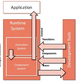
The data acquisition framework (DQF) is one of the fundamental building blocks of the GAMBAS middleware. Conceptually, the DQF is responsible for context recognition on personal mobile devices
including smart phones, PDA’s and laptops. The DQF supports various platforms including Android, Windows and Linux. The DQF is a multi-stage system. On the one hand it allows developing reusable context recognition applications. On the other hand it provides enabling relevant applications at a particular time automatically. Specifically the DQF consists of a component system and an activation system as shown in Figure 1.
Figure 1 – Data Acquisition Framework Overview
The component system uses a component abstraction to enable the composition of different context recognition stacks that are executed continuously. A context recognition stack or simply a configuration refers to a set of sampling, preprocessing and classification components wired together to detect a specific context. Examples of such context include physical activity of a person, location of a person, etc. These configurations can be used to detect context for multitude purposes and have applications in areas of smart home environments, assisted living for elderly, proactive route planning, budget shopping, etc.
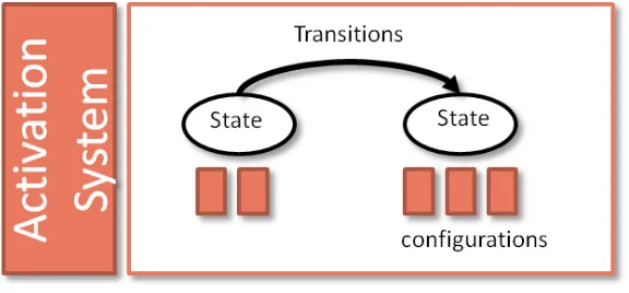
The activation system uses a state machine abstraction to determine the point in time when a certain configuration or a set of configurations will be enabled. The activation system enables the required configurations in an automatic manner based on the conditions associated with the state transitions. An example of a simple (coarsely granular) state machine associated with an employee could consist of two states “Working” and “Relaxing”. State “Working” may consist of configurations “Meeting”,
(transition for state change), for instance. In the following sections a more detailed description of the component system and the activation system is given.
2.1
Component System
In DQF, the user’s context and activity recognition is done using a component-based approach. This approach promotes reusability and rapid prototyping. It also gives us the ability to analyze application structures in order to optimize their execution in an energy efficient manner. In the component system each application consists of two parts, the part containing the recognition logic and the part containing the application logic. The part that contains the recognition logic consists of sampling, preprocessing and classification components that are connected in a specific manner as shown in Figure 2. The part that contains the remaining application logic can be structured arbitrarily. Upon start up, a context recognition application passes the required configuration to the component system which then instantiates the components and executes the configuration. Upon closing, the configuration is removed by the component system which eventually releases the components that are no longer required. The component system supports various platforms such as J2SE and Android. Using an Eclipse-based tool, application developers can visually create configurations by selecting and parameterizing components and by wiring them together.
Figure 2 – Component System Overview
2.1.1 Component Model
To structure the recognition logic, our component system realizes a lightweight component model which introduces three abstractions. First, components represent different operations at a developer-defined level of granularity. Second, connectors are used to represent both, the data- as well as the control-flow between individual components. And third, configurations are used to define a particular composition of components that recognizes one or more context characteristics.
2.1.1.1 Components
in contrast they can be instantiated multiple times and they are parameterizable to support different application requirements. Due to the parameters, the component model is more flexible than other models. Besides parameters, all components exhibit a simple life cycle that consists of a started and a stopped state. To interact with other components, a component may declare a set of typed input and output ports that can be connected using connectors.
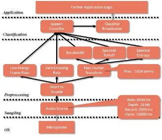
Figure 3 – Speech Detection Configuration Example
As depicted in Figure 3, the recognition logic of a speech recognition application consists of a number of components which can be divided into three levels. At the lowest level, the sampling components are used to gather raw data from an audio sensor. On top of sampling components, a set of preprocessing components takes care of various transformations, noise removal and feature extraction. Finally, the extracted features are fed into (a hierarchy of) classifier components that detect the desired characteristics. Depending on the purpose and extent of the application logic, it is usually possible to further subdivide the layers into smaller operators. Although, our component system does not enforce a particular granularity, such operators should usually be implemented as individual components to maximize component reuse.
2.1.1.1.1 Parameters
2.1.1.1.2 Ports
In order to support application independent composition, each component may declare a number of strongly typed input and output ports. Input ports are used to access results from other components. Output ports are used to transfer computed results to another component. Thus ports enable components to interact with each other in a controlled manner. The developer can add multiple input and output ports of different types without worrying about their memory allocation, ordering and memory de-allocation. The internal buffer management for the ports is transparent to the developer and done by the component system itself.
2.1.1.2 Connectors
In order to be reusable, components are isolated from each other by means of ports. However, the recognition of a context feature often requires the combination of multiple components in a specific way. Connectors express such combinations by determining how the typed input and output ports of different components are connected with each other. In order to minimize the overhead of the component abstraction, connectors are implemented using an observer pattern [GAMM1] in which the output ports are acting as subjects whereas the input ports are acting as observers. This enables modeling of 1:n relationships between the components, which is required to avoid duplicate computations. To avoid strong coupling between components, input ports do not register themselves at the output ports but the component system takes care of managing all required connections. An example of connectors can be seen in Figure 3, where the output port of the fast Fourier transform component is connected to the input ports of bandwidth, spectral roll off and spectral entropy components.
2.1.1.3 Configurations
Each context recognition application must explicitly list all required components together with their connectors in a configuration. While this approach slightly increases the development effort, it also increases the potential reuse of components that can be applied on data coming from different sources. As an example for such a component, consider a Fast Fourier Transform (FFT) that converts a signal from its time domain into the frequency domain. Clearly, such a component can be applied to various types of signals such as acceleration measurements or audio signals. Thus, by explicitly modeling the wiring of components as part of a configuration, it is possible to reuse such a component in different application contexts. In addition to listing components together with their connectors, the support for parametrizable components also requires the developer to explicitly specify a complete set of parameter values that shall be used by each component. As a result, every configuration consists of a parameterization as well as associated connectors. An example of a speech recognition configuration is shown in Figure 3.
2.1.2 Runtime System
energy efficient techniques if more than one application is executed simultaneously. When the applications do not require the context information anymore the runtime system stops executing the associated configurations. A detailed description of the component system structure and execution of applications is given in the following sections.
2.1.2.1 System Structure
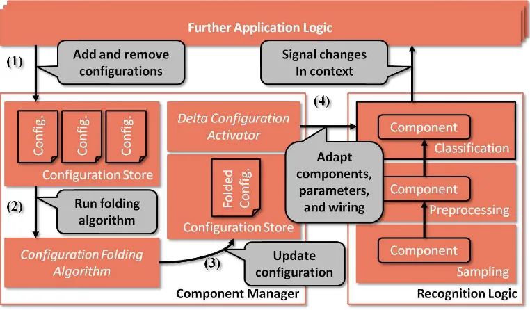
As shown in Figure 4, the main elements of the runtime system of the component system are the configuration store, the configuration folding algorithm [IQBA12] and the applications. The configuration store is used to cache the configurations associated with applications that are active. It is also used to store their folded configuration. The configuration folding algorithm provides energy efficient execution of context recognition applications provided more than one application is executed simultaneously. The entity responsible for managing the runtime system is called the component manager. The component manager is implemented as an Android service (recognition service) and must be installed on the device separately. When the application developer creates an application it must provide code to bind the application with this recognition service and when the application is finally deployed on the device and executed, the recognition service gets activated and instantiated and executes the configuration associated with it.
Figure 4 – Component System Structure
2.1.2.2 Configuration Execution
component manager does not directly start the components contained in the configuration. Instead, it uses the set of active configurations as an input into our configuration folding algorithm. The goal of the configuration folding algorithm is to remove redundant components that are present in different applications and perform the same sampling or compute redundant results. Using the set of configurations, the configuration folding algorithm computes a single, folded configuration that produces all results required by all running applications without duplicate sampling or computation. Once the configuration has been folded, the component manager forwards it to the delta configuration activator. By comparing the running and the folded configuration, the activator determines and executes the set of life cycle and connection management operations (starting, stopping and rewiring of components) that must be applied to the running configuration in order to transform it into the folded target configuration. When executing the different operations the delta activator takes care of ensuring that their ordering adheres to the guarantees provided by the component life cycle. To do this, it stops existing components before they are manipulated. The mentioned procedure is illustrated in Figure 4.
2.1.2.3 Platform Support
The core abstractions of the component systems as well as the component manager are implemented in Java 1.5. In order to support multiple platforms, different wrappers have been implemented that simplify the usage of the component system on platforms including Windows, Linux and Android.
2.1.2.4 Tool Support
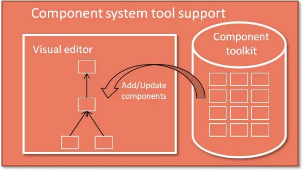
In addition to the platform support the component system provides offline tools to support rapid prototyping. These tools include a visual editor which is used for creating and updating configurations for the context recognition applications. The visual editor provides a user friendly interface which allows developers to drag, drop, parameterize and wire existing components to create new configurations or update existing ones. The visual editor is implemented as a plug-in for the Eclipse IDE (Version 3.7 and above).
In addition to the visual editor the component system provides a large set of sampling, preprocessing and classification components as part of the component toolkit. At the sampling level, our toolkit provides components that access sensors available on most personal mobile devices. This includes physical sensors such as accelerometers, microphones, magnetometers, GPS as well as Wi-Fi and Bluetooth scanning. In addition, we provide access to virtual sensors such as personal calendars, etc. For preprocessing, the toolkit contains various components for signal processing and statistical analysis. This includes simple components that compute averages, percentiles, variances, entropies, etc. over data frames as well as more complicated components such as finite impulse response filters, fast Fourier transformations, gates, etc. Furthermore, the toolkit also contains a number of specialized feature extraction components that compute features for different types of sensors such as the spectral rolloff and entropy or zero crossing rate which are used in audio recognition applications or Wi-Fi fingerprints which can be used for indoor localization. At the classification layer, the toolkit contains a number of trained classifiers which we created as part of the audio and motion recognition applications. Furthermore, there are a number of platform-specific components which are used to forward context to an application which enables the development of platform-independent classifiers. In Android, for example, a developer can attach the output of a classifier to a broadcast component which sends results to interested applications using broadcast intents. We have also developed a number of components that are useful for application development and performance evaluation. These includes components that record raw data streams coming from sensors as well as pseudo sensors that generate readings using pre-recorded data streams. Together, these components can greatly simplify the application development process on mobile devices as they enable the emulation of sensors that might not be available on a development machine. The tool support for component system is depicted in Figure 5.
2.2
Activation System
To fully understand the context of an entity, usually more than one context characteristics are required. As an example, to know if a person is working in his office, context characteristics such as his location, pattern of movement, types of meetings, classification of ambient sounds etc. are required. As described earlier, such context characteristics can be detected using the component system by developing configurations with the appropriate components, parameterizations and connections. Furthermore, in order to fully identify a particular context more than one configuration would be needed at a particular time. In real life, however, the context of an entity does not remain static and over the period of time requires detection of different/new context characteristics.
Moreover, the context of an entity is dependent upon the task that the entity is involved in. In other words, to know the context of an entity it is essential to know the task that the entity is involved in. Furthermore, these tasks usually follow a fixed pattern, e.g. tasks that a working person usually has consist of waking up in the morning, dressing up according to the weather, traveling to the work place, sitting in the office, holding meetings and discussions, going for lunch and coffee breaks, working on a computer, going for shopping, going home, relaxing, having dinner, sleeping, etc. The example shows that a routine of an average working person is quite predictable, at least partially. We can also further break the individual tasks mentioned in this example into smaller tasks e.g. when a person travels to his workplace, he either walks, drives his own car or takes a public transport.
Given the presence of such regular patterns of reoccurring tasks, the goal of the activation system is exploit the knowledge about their existence in order to minimize the amount of sampling and processing that is needed to detect the user’s context. To do this, the activation system enables a developer to model individual tasks as a set of states that occur sequentially. For each of the states, the developer may specify a set of configurations that describe the context that shall be recognized. In addition, the developer specifies a set of transitions between the states that define possible sequences. Using this model, the activation system takes care of executing the right configurations at the right time. In the following, we describe this basic idea in more detail.
2.2.1 Activation Model
In the GAMBAS DQF, modeling of routines of a user’s tasks is managed by the activation system, which uses a state machine abstraction to model them. Specifically, the activation system enables the automatic, state-based activation of different configurations associated with developer defined
tasks. Hence, in our activation system, the entity’s context irrespective of the granularity is modeled as a state with different configurations associated with it. The transitions between the states are modeled using a rule based approach, e.g., if for a state “working”, the associated configurations provide negative results or results not up to a certain threshold, the activation system uses this to trigger an associated state transition.
2.2.1.1 States
A state refers to a particular decision point during the execution of a larger task. It entails a set of configurations that individually detect different context characteristics but collectively identify one of the possible decisions taken by the user.
Thereby, states may be used at different levels of granularity. An example for a coarse grained state is shown in Figure 7(a). In this example, a “Working” state may encompass configurations that detect whether the person is in a meeting, working in his office or having lunch at the canteen. An example for a fine-grained use of state is shown in Figure 7(b). Here, the state “Fast Sampling” may be used in
conjunction with a “Slow Sampling” state in order to control the precision of a certain set of
configurations such as a movement detector and a sound classifier.
Figure 7 – Examples of Activation System States
2.2.1.2 Transitions
Transitions are defined by the conditional changes in the configurations associated with a state. When the changes suggest a certain condition holds, the activation systems disables the current state and associated configurations and enables the ones associated with the new state. This is done by modeling the transitions using a rule based approach. Each transition is represented by an abstract syntax tree, in which conditions or thresholds for each configuration are evaluated. Depending upon the evaluation of the abstract syntax tree, the activation system decides whether a state change has occurred or not.
Figure 8(a) shows two example states. State 1 has two configurations, configuration A and configuration B. State 2 also has two configurations, configurations C and configuration D. The transition from State 1 to State 2 is labeled as Transition 1 2 and transition from state 2 to state 1 is labeled as Transition 21. The abstract syntax tree for Transition 12 and Transition 21 is shown in Figure 8(b) and Figure 8(c) respectively. Assuming that State 1 is currently the active state, the activation system continuously evaluates the abstract syntax tree for Transition 12 and when the outcome of the tree, here represented by an AND operator is true it will disable Configuration A and Configuration B and enable Configuration C and Configuration D. Similarly when State 2 is the current state, the activation system evaluates the abstract syntax tree associated with Transition 21.
2.2.2 Runtime System
The main task of the runtime system is to load the state machine pertaining to a user and as indicated by the application logic, instantiate the configurations associated with states, identify the current state, instantiate rules for different transitions and evaluate the abstract syntax trees associated with the respective transitions. Furthermore, the activation system executes the state machines in an energy efficient manner by applying configuration folding among all configurations across all the different states. The outcome of such a “folded” state machine is a single folded configuration. Clearly, it is possible that in such a folded configuration different configurations share the same graph structure, at least to a certain level. Therefore the activation system provides appropriate logic for evaluating transition between the states. Further details on how this can be achieved are described in the following sections.
2.2.2.1 System Structure
Figure 9 – Activation System Structure
2.2.2.2 Configuration Mapping
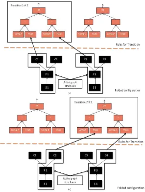
In this section we describe how different configurations related to different states are folded and how the rule engine applies rules representing transitions between the states. To understand the mappings consider an example of a state machine with two states as shown in Figure 10(a). Each state has two configurations attached to it. When the activation system loads the state machine it applies the configuration folding algorithm on all configurations associated with both states and the result is shown in Figure 10(b).
Let’s assume the following rules for the two transitions:
Transition 12: IF result of Config. A OR result of Config. B EQUALS FALSE then State 2 Transition 21: IF result of Config. C OR result of Config. D EQUALS FALSE then State 1
Their abstract syntax trees and how they are integrated with folding is shown in Figure 11.
Figure 11 – Example for Active Graph Structures in Folded Configuration
Let’s assume that the current state of the state machine is State 1. In this case the configurations to
2.2.2.3 Platform Support
The core abstractions of the activation systems will be implemented in Java 1.5. In order to support multiple platforms, different wrappers will be implemented that will simplify the usage of the activation system on platforms including Windows, Linux and Android.
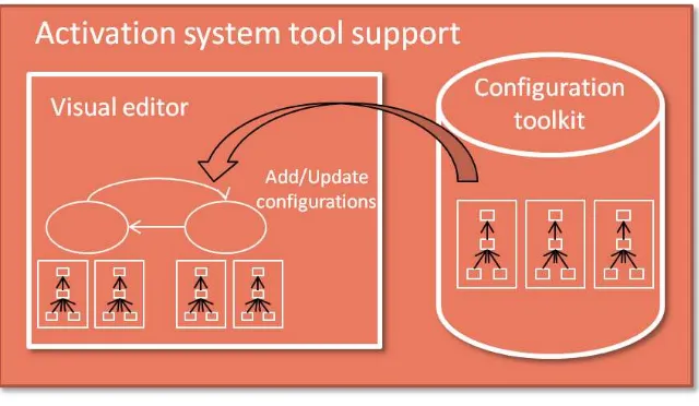
2.2.2.4 Tool Support
In addition to the platform support the activation system will provide offline tools to support rapid prototyping. These tools will include a visual editor which will be used for creating and updating configurations for context recognition applications. The visual editor will provide a user friendly interface which will allow developers to drag, drop, parameterize and wire existing configurations to create new state machines or update existing ones. The visual editor will be implemented as a plug-in for the Eclipse IDE.
Figure 12 – Activation System Tool Support
3
Context Recognition Components
The context recognition components are the basic building blocks of a context recognition application. The component toolkit provided with the component system consists of a large number of sampling, preprocessing and classification components. These components can be used to create new applications. Moreover, with the toolkit support developers can implement their own components with little effort. For the scope of this project and test applications to be developed we mostly focus on physical activity recognition, location recognition and audio recognition components. During the second iteration of the implementation, location prediction and duration components will also be developed. These components will be able to predict next location of the user and also their intended stay at a particular location. With the help of such prediction components application built on top of GAMBAS middleware will be able to provide users with timely and relevant services. On the other hand the service providers will be able to better plan their businesses and services models.
Figure 13 – Context Recognition Components Overview
3.1
Activity Recognition Components
Based on the scenarios defined in the [GCUC12] the activity recognition components will mostly be recognizing travel-related information. The travel related information has different aspects of the information relevant for different kinds of users e.g. the travel related information is different for a single user from a group of users and travel related information of a group of users is different from transport regulating authorities as well as transport providing companies. Using the relevant information single users or group of users can plan their trip efficiently and transport provider can provide better services. Example of travel related information for a single user or group of users may include the best possible route to reach their destination. The notion of best depends upon the users preferences and it can mean the fastest route or the route in which users can do some shopping or meet a friend, for instance. For the transport providing companies, the users travel related information (his route, preferences) can help them adding more busses to a route or removing busses from the routes, displaying relevant advertisements on screens installed in busses or offering different kinds of incentives when the user is onboard the bus, for instance.
recognition components. With the activity recognition components the system can identify that the user has started moving or performing an activity that may trigger the system to compute routes for a pre-stored destination for him. Example of such an activity could be climbing down the stairs, closing door of his office or house. The activity recognition component may also be used to detect if the user is standing or sitting in the bus. This may help transport providers to alert other users about the crowdedness in the busses. The location recognition component may tell where the user is and based on this information the service providing companies can offer different incentives to him. An example of such an incentive could be that if the transport providing company knows that the user is in Bus 933 near University of Duisburg-Essen, then transport provider may alert the user to visit a newly opened café in the vicinity. The audio recognition components may sample and record the ambient sounds to alert the user of any important announcement being made in the bus or can also be used find out the level of noise pollution in the environment.
3.1.1 Location Recognition
In order to perform location recognition our components will rely on radio signal based and GPS techniques as opposed to image processing or any other kind of techniques. As mentioned earlier that the context recognition for the user will be done using the user’s smart mobile phone, therefore we will be solely relying on the on-board sensors on the mobile phone to gather the information on these radio signals. Specifically, we will be using information from GPS, GSM and Wi-Fi sensors of the phone. Each of them has its own advantages and limitations but their collective use can provide efficient and accurate location recognition. With the wide spread use of Wi-Fi a user can typically see multiple Wi-Fi access points in the surroundings. With the limited range or signal strength of a typical Wi-Fi signal, a user can see different set of access points as he moves from one location to another. Thus capturing this information alone can provide user with a fair bit of idea about his location. However, places where Wi-Fi signals are not available or are very weak e.g. in outdoor location such as shopping markets, play grounds etc. GSM signals can be used. Typically a mobile phone can report up to 6 neighboring cell towers. Though range of a GSM cell tower is usually large and same locations may receive same information about the cells, together with Wi-Fi, GSM can provide accurate location information. Lastly, we will also make use of GPS signals in outdoor locations where Wi-Fi and GSM signals are not present or are very weak. Since each of these technologies have different energy requirements, energy efficient techniques will be developed to perform the location recognition.
3.1.2 Trip Recognition
Knowing the location of a user is an important piece of information both for the users as well as for the transport service providers. Having information about the mode of locomotion between two locations could be beneficial for service providers or in other words to know how the trip was done meaning whether the user went on foot, took a car or a bus, stood in the bus or was able to find a seat and if the user also used trains or trams in between could help service providers to offer better services. In order to know the mode of locomotion we will develop multistage classifiers which will use different sensors such as accelerometer, W-Fi, GSM to identify the mode of locomotion. We will combine information from all these sensors in a systematic way to identify different types of vehicle. In short, we will use accelerometer to identify the motion of the user. Using accelerometer alone, it is possible to identify if the user is walking, running, climbing stairs etc. If a continuous detection of walking or running is detected between the locations, it means that the user went on foot. This can be verified by looking at the rate of GSM cell changes between the locations. If the rate of cell change is fast then it would mean that the user is in some kind of vehicle, once the system detects that it further detects the type of vehicle. If there is some regular acceleration and deceleration experienced by the system, it would correspond to the acceleration and breaking in a car or a bus. Furthermore if the accelerometer detects that the user is standing and there is a high level of engine sound in the surrounding, the system would detect mode of locomotion as a bus. Similarly, using the similar approach the system will be able to detect if the user is in a vehicle within city limits or travelling on motorways.
3.2
Intent Recognition Components
The intent recognition components take the recognized locations and trips and provide future predictions on them. Knowing the current location and mode of user transport provides significant opportunities to the service providers to improve their business but the added ability to predict how long the user will stay at a particular place and what would be his next destination could help service providers to offer even more useful services. Apart from the service providers, a user can have many personal applications that can take advantage of this information e.g. there can be a device charge reminder application which can alert the user to charge the batteries based on the predicted duration of his stay at the current location and also his intended next destination. Therefore, in order to meet these objectives the acquisition framework will provide duration prediction and destination prediction components.
3.2.1 Duration Prediction
In order to know that how a long a user will stay at a particular place requires storing user location and running offline analysis to compute predictions for the duration of user’s stay at the same place in the future. There can be different options to store information about user’s stay at a particular location e.g. this information can be stored in users’ device, in the cloud and also at third party
trusted servers. We believe that storing such information other than on user’s device is prone to
in addition to previously stored data which includes the information about the frequency of the
user’s visit to that location and his usual next locations. The system then runs different prediction algorithms to compute new predictions or update existing ones. This offline analysis of data is usually done whenever the device is plugged in to a socket and charged for a longer time e.g. during the night.
3.2.2 Destination Prediction
In addition to knowing the current location and stay of a user at a particular location, the ability to predict the next user destination is also very useful. This information can be used to compute the transport routes proactively, for example. Similar to the duration prediction, the destination prediction is performed by analyzing the history of places visited by the user. This mainly involves identifying some sequence in the places visited by the user, the time of the day, the day of the week and frequency of visits etc. e.g. On every Saturday the user first go for shopping, then go to a fitness club and afterwards meet friends and family. Similar to the duration prediction, this information is stored on the device and offline analysis (when the device is being charged) is performed to compute new predictions or update the existing ones.
3.3
Sound Recognition Components
The sound recognition components are supposed to make use of the combination of audio-data collected on the mobile device and location data. They can be used for two major purposes. One of
them is to support the input of the user’s intended next location by allowing him an easy and fast
way of entering his destination. The related process will be called voice-tagging. The other purpose consists in the extraction of the current user context by exploiting given background sound.
3.3.1 Voice-Tagging Component
Every application user will have certain locations he attends frequently, for example his home or his work place. To enable the user to enter these locations as destination most efficiently the voice-tagging component will be built. In a first step it offers the user to add a short audio tag to his current
whereabouts. For this purpose there will be a button saying “voice tagging” which, when pressed,
starts a short audio recording. Typically the audio input will contain a sequence of one to three words spoken by the user. This audio is then, in a reduced form, stored in the database connected with the current geodata, provided by the location recognition component, and the UserID. At any later point in time the user can refer to his audio tag by entering extremely similar audio, which would normally
mean phrasing the same words he used for the tagging. So if he had tagged a place by saying “my
3.3.2 Noise Map Component
There are several user contexts that come along with a characteristic sound environment. Being on a crowded bus for example a person is surrounded by a constant bus engine sound as well as human voices and other noise created by a crowd of people. This shall be exploited to extract information about the user context from audio collected on the mobile device as well as to gather information about the public transport traffic situation in the whole city. In the first step audio data will be collected from two sources. The first source are microphones that are already permanently installed in public buses owned by EMT. The second source will be mobile devices carried around the city by test users who will record several distinct audio environments like crowded bus stations and traffic jams. The collected data will then be used to create sound profiles of different environments at different states, e.g. crowded, not crowded, daytime, nighttime, rush hour, etc. the result of this elaboration will be called noise map. It can later be used to determine, for example, if a certain bus is already carrying too many people which would then enable other system components to calculate and suggest more comfortable travel routes. At the same time the created sound profiles support the extraction of user context information. If the user allows sound context acquisition, the audio data captured in the current user environment will be compared to the noise map. The resulting similarities can add to the location and trip recognition.
3.4
Speech Recognition Components
In order to maximize the usability of the application, the fast and very natural method of speech input shall be enabled. In addition to increased speed and convenience this will also permit barrier-free handling of the application. A recognition engine that is embedded on the device would assure to meet the highest privacy standards. But since the computation of audio data turns out to be very resource-intensive an embedded speech recognition process achieves a lot lower recognition quality and performance compared to server-based recognition. However, in the scope of this project an embedded recognition process might suffice in quality and performance especially since the potential speech input will be limited to a certain group of words. This will be evaluated during the implementation phase.
3.4.1 Voice-Control Component
The idea of the voice-control component is to enable the user to tell the application where he wants to go next by simple speech input. The component will be activated via a voice-control button within the user interface. It will receive audio data and return, if recognized, a location, otherwise it will
simply return zero. A typical speech input would be “I want to go to the main station.”
4
Acquisition Framework Integration
This section briefly describes the integration of data acquisition framework (DQF) with the other system elements of GAMBAS middleware. The two other system elements with which the DQF directly collaborate are the privacy preserving framework (PRF) and the semantic data storage (SDS) as part of interoperable data representation and query processing work package. As described in [GCAD12] and depicted in Figure 13, the data collection by the user’s device – either for personal or the collaborative use – requires the device to store the data either locally or remotely, depending upon the required services from the service providers. In either case there is need for local and remote interfaces between these two system elements to store the data in appropriate manner and in the right format. Another key feature of the GAMBAS architecture is the privacy preserving exchange of the user’s context data with the service providers and for this reason the PRF resides on
the user’s device. In order to ensure that only the data in accordance with the privacy policy of the
user is sent to the service providers, there is need for control interfaces between these two system elements. In the following, we briefly outline the core functionality of these interfaces. A full description of them, however, goes beyond the scope of the first version of this document. A more detailed description will be integrated into the second version.
Figure 14 – Integration of DQF, SDS, PRF
4.1
Semantic Data Storage
4.2
Privacy Framework
The main purpose of the privacy framework in GAMBAS middleware is to allow a controlled access to the personal and private information about the user. Since the potential services targeted in GAMBAS require service providers to access context information of the user, it is of utmost importance that only the relevant information is shared with the right resolution to the right service provider. As already specified, the context information is gathered and processed through the DQF in the personal mobile device of a user, therefore, the PRF and the DQF must communicate so that the context data is exported in a privacy preserving manner.
As every export of user’s context information is filtered based on the privacy policy of the user, therefore, for every request of data by the service provider, the DQF checks it with the privacy
framework. If the PRF allows the data to be sent, only then the users’ context information is
5
Requirements Coverage Analysis
In order to check whether the requirements about the data acquisition framework specified in D1.1 are covered in this specification, we perform a requirement coverage analysis to validate the design and details of the data acquisition framework given in the above sections. In the requirements specification document the requirements are categorized according to various work packages. Moreover the requirements are further sub classified in to different categories. Below we perform requirements coverage analysis according to the subcategories of requirements related to the adaptive data acquisition framework.
5.1
Framework-related Requirements
The framework related requirements define different requirements on the adaptive data acquisition framework. In the following, we briefly discuss whether they are covered and if so, were the associated discussion can be found.
ID AA_001
Description The data acquisition framework shall allow multimodal data acquisition.
Type Functional and data requirements
Priority High
AA_001: This requirement has been covered in Section 2.1. As the data acquisition framework is required to capture different sorts of context data, it will use different sensors available on the mobile phone e.g. microphone, accelerometer, gyroscope, GPS, Wi-Fi etc to do it.
ID AA_002
Description The data acquisition framework shall be extensible.
Type Functional and data requirements
Priority High
AA_002: This requirement has been covered in Section 2.1. The design description for the data acquisition framework given in previous sections ensures that the framework is extensible with regard to addition of new components, configurations, applications etc.
ID AA_003
Description The data acquisition framework shall allow automated acquisition of context data.
Type Functional and data requirements
Priority High
ID AA_012
Description The data acquisition framework shall allow optimization of context recognition components by allowing configurable parameters.
Type Functional and data requirements
Priority High
AA_012: This requirement has been covered in Section 2.1.1.1.1. The component model described above allows developer to add/update parameters in the components to optimize their use.
ID AA_004
Description The data acquisition framework shall be lightweight.
Type Performance requirements
Priority Medium
AA_004: This requirement has been covered in Section 2. The entire data acquisition framework is meant to be executed on constrained computer systems such as mobile phones. Therefore, the design for the framework (component system and activation system) presented in the above sections has been created with a very high consideration to this requirement.
ID AA_007
Description The data acquisition framework shall enable energy efficient context recognition for several applications.
Type Performance requirements
Priority Medium
AA_007: This requirement has been covered in Section 2.1.2. The component system and the activation system applies configuration folding on simultaneously executed configurations such that there is a single folded configuration for all with minimized occurrences of redundant computations.
ID AA_009
Description The data acquisition framework shall provide a control interface to the privacy framework.
Type Functional and data requirements
Priority High
AA_009: This requirement has been covered in Section 4.2. A control interface is need for the two
frameworks to ensure that the user’s context data exported to the service providers is according to
the privacy policy of the user. A more elaborate description will be provided with version 2 of this document.
ID AA_026
Description The data acquisition framework should provide an API to discover the types of data that are used to derive other data.
Type Functional and data requirements
Priority High
AA_026: This requirement has been covered in Section 4.1. A control interface is need for the two
ID AA_025
Description The data acquisition framework must be able to support the acquisition of public transport co-use.
Type Functional and data requirements
Priority High
AA_025: This requirement has been covered in Section 3.2. Using the trip recognition, duration prediction and destination prediction components the data acquisition system will be able to provide co-use of public transport by friends or colleagues.
ID AA_005
Description The data acquisition framework shall be able to classify audio data.
Type Functional and data requirements
Priority High
AA_005: This requirement has been covered in Section 3.3 and 3.4. The component system provides speech and sound recognition components for detecting ambient sounds, announcements, discussions, etc. Moreover, with these components the user can speak his preferences to the system instead of typing.
5.2
Developer-related Requirements
The developer-related requirements define different requirements on the adaptive data acquisition framework from an application developer’s perspective. In the following, we briefly discuss whether they are covered and if so, were the associated discussion can be found.
ID AA_019
Description The data acquisition framework shall allow the reuse of components to recognize different types of context.
Type Functional and data requirements
Priority Low
AA_019: This requirement has been covered in Section 2.1.2.4. The components once developed become part of the component toolkit. Developers can use this toolkit and reuse the existing components in their applications which can have totally different requirements from the applications for which the components were first developed.
ID AA_013
Description The data acquisition framework shall provide tools to simplify the offline training for recognizing different types of context.
Type Functional and data requirements
Priority Low
ID AA_022
Description The data acquisition framework shall provide tool support to simplify the development of new methods to recognize context.
Type Functional and data requirements
Priority Low
AA_022: This requirement has been covered in Section 2.1.2.4 and 2.2.2.4. Both, the component system and the activation system will be equipped with toolkits and visual editors, which will allow the development/update of new /existing components and configurations.
5.3
Data-related Requirements
The data-related requirements define different requirements on the adaptive data acquisition framework from a data acquisition perspective. In the following, we briefly discuss whether they are covered and if so, were the associated discussion can be found.
ID AA_014
Description The activity recognition components must be able to capture the past user locations in an energy-efficient manner.
Type Functional and data requirements
Priority High
AA_014: This requirement has been covered in Section 3.1.1. The locations which a user visits are captured using the Wi-Fi fingerprints and if needed using the GSM or GPS. The capturing of finger prints is done stage wise e.g. it is activated only when other sensors such as accelerometer indicates movement of any kind. Moreover, the processing for the captured location is only done when the device is being charged.
ID AA_016
Description The localization performed by the activity recognition components should not expose the user's location to untrusted third parties.
Type Usability and humanity requirements
Priority High
AA_016: This requirement has been covered in Section 4.2. User’s location data is only exposed to the third parties or service providers if and only if the privacy policy of the user allows that. A more elaborate description will be provided with version 2 of this document.
ID AA_017
Description The activity recognition components must be able to capture the mode of
locomotion.
Type Functional and data requirements
Priority High
ID AA_023
Description The intent recognition component must record context histories in a storage-efficient manner.
Description The intent recognition components are able to predict the next location of a user.
Description The intent recognition components are able to predict the stay duration of the user.
Type Functional and data requirements
Priority High
AA_018: This requirement has been covered in Section 3.2.1. The duration prediction component allows service providers to know how long the user will stay at the current location so that they can provide timely and relevant services to him.
ID AA_020
Description The sound recognition components shall enable the classification of different environmental sounds.
Description The speech recognition components support server-less operation with a
limited vocabulary.
Type Functional and data requirements
Priority High
6
Acronyms
Acronym Explanation
DQF Data Acquisition Framework PRF Privacy Framework
SDS Semantic Data Storage
GAMBAS Generic Adaptive Middleware for Behavior-driven Autonomous Services
GPS Global Positioning System
GSM Global System for Mobile Communication
Wi-Fi Wireless Fidelity
7
Conclusion
This document described the details about the adaptive data acquisition framework to be developed as part of WP2 of GAMBAS project. The document has described different building blocks for the framework which mainly includes the component system and the activation system. The document has also highlighted different context recognition components to be developed during the course of the project. This document is a result of requirements specification document, use case and architecture overview documents of GAMBAS released in the previous months.
8
Bibliography
[ANDR] Android Project, Project Homepage, September, 2012, online at http://developer.android.com/
[BASE] BASE Project, Project Homepage, September, 2012, online at http://code.google.com/p/pppc-base/
[GAMM1] R. J. J. V. Erich Gamma, Richard Helm, “Design patterns elements of reusable object-oriented software, publisher: Addison-Wesley.”
[GCRS12] GAMBAS Consortium, Requirement Specification, Public Deliverable D1.1, May, 2012, online at http://www.gambas-ict.eu
[GCUC12] GAMBAS Consortium, Use Case Specification, Public Deliverable D1.2, May, 2012, online at http://www.gambas-ict.eu
[GCAD12] GAMBAS Consortium, Architecture Design, Public Deliverable D1.2.1, July, 2012, online at http://www.gambas-ict.eu