AN IMPROVED PROGRESSIVE TRIANGULATION ALGORITHM FOR
VEHICLE-BORNE LASER POINT CLOUD
Zhanying Weia,b,, Hao Maa,b, Xuexia Chena,b, Lirong Liua
a Chinese Academy of Surveying and Mapping, Beijing 100830, PR China
b Beijing Advanced Innovation Center for Imaging Technology, Capital Normal University, Beijing 100048, PR China
Commission III, WG III/6
KEY WORDS: Vehicle-borne laser point cloud, Ground filter, TIN, Progressive triangulation, Improvement
ABSTRACT:
The application of classical progressive triangulation filter algorithm for airborne point cloud is very successful, however, there is a big difference between airborne point cloud and vehicle-borne laser point cloud in spatial distribution, density and other aspects. In this paper, a lot of experiments are carried out to improve the filter algorithm for vehicle-borne laser point cloud, which includes as follows: (1) Establish grid index, such as 0.1 meters, only retain the lowest points, which can greatly reduce the number of suspected ground points, and the filtering efficiency is improved significantly; (2) According to the vehicle-borne height and track line, the road face points can be roughly determined. Then the convolution operation is used to ensure the real road points, which are also the ground points. This method cannot have to relax the filter parameters (which will lead to more non-ground points) and ensure the integrity of the road boundary; (3) A method named as "get more and remove some" is proposed for solving the filtering faults at the tail of every points segment caused by the incline scanning face. After the three steps, the filtering is improved obviously on qualification and processing speed.
Corresponding author ([email protected]) 1. INTRODUCTION
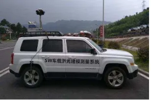
Lidar is a spatial information acquisition technology developed rapidly in recent years, which can get the coordinates and the intensity of the visible ground features with high speed and high precision. Lidar is mainly mounted on the aircraft for ground scanning, the distance between points is about one meters or more and the points are mainly used to produce DEM/DSM less than 1:1000 scales before. At present, the VLS (vehicle-borne laser scanning) is also widely used. VLS means equip the motor vehicle-borne with the global positioning system, inertial navigation system, laser radar scanning system, digital camera or video equipment, synchronize all devices, collecting the spatial point cloud and images of road and features near the road when vehicle-borne moving, then form a variety of useful thematic information by post-editing (LI Deren, 2006).
Figure 1. Vehicle-borne Laser Scanning System.
Vehicle-borne laser point cloud can be used to extract urban components with high precision, perform large scale mapping, establish urban 3D models, and form a high precision pavement
DEM. Filtering technology for airborne point cloud has been mature. Main methods include triangulated irregular network encryption filter, slope-based filtering, filter based on mathematic morphology and filter based on mobile interpolation, etc. Because airborne point cloud come from the sky sensor, point cloud is relatively uniform and the point spacing is too large. Vehicle-borne laser point cloud coming from the sensors near the road have large density but uneven distribution. Therefore, the filtering method for airborne point cloud would encounter many problems when applied to vehicle-borne laser point cloud. Some scholars improved airborne filtering method to adapt vehicle-borne laser point cloud. Improved mathematical morphology was proposed (Sui Lichun, 2011); An object oriented method for vehicle-borne laser point cloud filtering is proposed (Fang Huale, 2011); A grid based hierarchical approach proposed (Tian Maoyi, 2013); A method based on scan line proposed (Guan Haiyan, 2007). Among which, the classical algorithm “progressive encryption method for irregular triangulation network”(Axelsson, 1999) is most widely used. Many scholars have improved the method to apply for the vehicle-borne laser point cloud(Li Hui , 2009; Zeng Nihong, 2016).
2. ALGORITHM DESCRIPTION AND IMPLEMENTATION
2.1 Characte ristic of vehicle -borne laser points and data conte nt
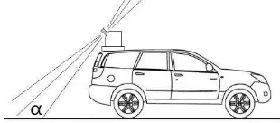
VLS can obtain point cloud directly, quickly and accurately, with collection efficiency generally 200 thousand ~100 million per-minute and points spacing generally 1~10cm. The scanning lines spacing is related to vehicle-borne moving speed and laser rotation speed, generally 5~20cm. In addition, the laser is usually mounted in the rear of the car to reduce the blocking situations from the car itself, the scanning surface (i.e., the surface formed by the rotation of the laser) is generally 30~45 degrees towards the pavement, as shown in Figure 2.
Figure 2. Scanning surface of vehicle-borne scanning system.
When driving, car track, UTC time, the angle and distance of laser points on the scanning surface are recorded. Spatial coordinates of laser point XYZ can be calculated according to the spatial posture relationship of the various sensors previously known. Information, such as mileage, time, height and lateral distance relative to track line, are endowed to each laser point, so the information of final vehicle-borne laser point cloud includes the following:
X, Y, Z //Cartesian coordinate of point cloud T //time
For data management, storage, display and other applications, points cloud is divided into separate files according to a certain number of points, for example200 million points. The current vehicle-borne laser range is generally 300~500 meters, but the points density is not enough and occlusion is serious in a far place, so generally speaking only the points in 100 meters range is taken, in sum up there are 200 meters from left side to right side. About 2 million laser points can be got when moving 200 meters at the speed of 50km on the road. The experimental data in this paper is the file with the 2 million point cloud. The files of this size are also more conducive to the establishment of quandary tree and 3D visualization of LOD structure.
2.2 Eliminate useless points quickly
The spatial distribution of the point cloud is very different from the airborne point cloud. The spacing of the points on the road is about 1cm, the value is around 10cm at the distance of 50 meters away and increase to 20cm from 100 meters away. In addition,
because the vehicle-borne system moves on the road, a large number of laser points belong to the side of the surface such as street lights, wall, trunk, canopy and so on. For ground point extraction, those overstocked laser points and the points on the side of features are useless. However time is wasted and points are still discarded in the process of filtering. In this paper, a method of dense grid index is proposed to perform pre filtering, and a large number of useless points can be directly discarded.
There are two ways to build such a grid: (1) In Descartes coordinate system
Then, calculate the resident cell for of each laser point: cr = y-minY /d + 0.5;
cc = x-minX /d + 0.5;
(2) In vehicle-borne coordinate system
Suppose the data scope of single points file is: minAX,minAY, maxAX,maxAY, and the cell size is d:
Then,
row = (maxAY -minAY)/d + 1; colume = (maxAX-minAX)/d + 1;
Then, calculate the resident cell for of each laser point: cr = ay-minY /d + 0.5;
cc = ax-minX /d + 0.5; As shown in Figure 3.
Figure 3, Mesh partition in vehicle-borne coordinate system
2.3 Extraction and application of pavement points
The purpose of ground filtering is to eliminate the plants, buildings, streetlights, poles, isolation belt and other features above the undulating ground and get clean ground points. A favorable fact is that there is no features on the pavement, the pavement surface is relatively flat and the slope is within design standards, so pavement points can be picked up by using these characteristics. Then the pavement points can regard as an important seeds for subsequent ground points extraction.
There is a very clear characteristic in vehicle-borne point cloud. The points below the vehicle-borne must be the pavement points and also be the ground points as well. Pavement detection can be carried out by selecting the height difference between these points in a certain threshold δAZ and lateral distance to the vehicle-borne in a certain threshold (δAX). The method of this paper is the convolution computation between neighborhoods, that is: find the 8 neighborhoods, get absolute value of Z-difference (δZ) for every neighborhoods and sum them up (ΣδZ). If ΣδZ is less than the threshold, the point is the target point, that is pavement point.
δAZ is set around 20cm generally, δAX is determined by the pavement width. Σ|δZ| is set from 10cm to 20cm. It is of high points density on pavement, so each cell contains point definitely except occlusion region. Therefore, the total number of valid neighbors (cell which has point) also can be taken as a threshold, so points with less than 8 valid neighbors does not belong to pavement.
Two methods can be used to construct the pavement mesh as mentioned in 2.2. The method (2) is proposed in this paper, which is construct in vehicle-borne coordinate system. The advantages are that it can reach to the boundary of pavement as far as possible and improve the accuracy of pavement points(see Figure 1). The extraction is of more efficiency than the classical algorithm proposed by Axelsson, because the later need more search and calculation but the former just need simple traversal, summation and comparison.
It is not necessary to rebuild the mesh in other areas outside the pavement which will apply for the classical algorithm. Seed points can be searched based on the mesh already established, that is: searching all the lowest point every N cells span, together with the pavement points as the final seeds for subsequent filtering. The calculation of span number is: suppose maximum length of the building is 10m and cell size is 0.2m, then the spans is 10/0.2=50. So in other word, searching one the lowest point in every 50*50 cells. In addition, the total number of valid cells is also an important threshold in the 50*50 scope. If the valid number is less than, for example, 100, it is believed that the scope contains no ground points.
2.4 End processing
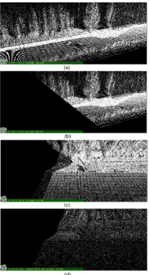
As mentioned earlier, there is a certain angle between the scanning surface and the ground, see Figure 2, and each 2 million points are saved in one file for management and applications, so an oblique scan surface is formed at end of each file. But there may be no ground points under the scanning surface, so the points on the scanning surface will be taken as ground point, then error happens, for example scanning surface contains tree points, as shown in Figure 8 (b), (c).
In this regard, the solution proposed in this paper is as follows: Borrow a amount of points from the next file adjacent to it, do the filtering, then delete some points in some mileage scope. The number of borrowed points depends on the height of the road slope and the angle of the scanning surface. Suppose the angle is 45 degrees and the slope height is 20 meters, then points in 20 meters mileage of adjacent file should be borrowed. In addition, in order to reduce the boundary error in constructing TIN, a litter more data are needed, 20.5 meters are better.
3. EXPERIMENTAL RESULTS
3.1 Building mesh to discard most useless points .
as shown in Figure 4 & Figure 5.
Figure 4. Mesh filtering to reduce invalid points - urban areas. Where, (a)The original 1.95 million points. (b) 0.1m cell size, getting 0.25 million lowest points. (c) 0.22 million ground points are obtained.
Figure 5 Mesh filtering to reduce invalid points - highway areas.
Where, (a)The original 1.97 million points. (b) 0.1m cell size, getting 0.56 million lowest points. (c) 0.51 million ground points are obtained.
be better than regions of large fluctuations. So this pre-processing is highly recommended in fluctuant areas.
3.2 Filte ring Comparison in different coordinate syste ms
Fig. 6 Comparison of the two kinds of mesh filtering.
Where, (a) Original 1.95 million points (1.33 million showed on screen). (b)Extract 0.115 million ground points in Descartes coordinate system. (c) Extract 0.15 million ground points in vehicle-borne coordinate system.
This experiment uses the same parameters, such as the distance from point to triangle face, the angle to the triangle face and the minimum distance between two ground points. In vehicle-borne coordinates system, more ground points are picked up, and the ground points are more reasonable. There are two reasons support the results. First, the method makes full use of the characteristics that the density of the pavement points is larger than it is in other areas, so more pavement points are picked up. Secondly, the relationship between the points distribution and the lateral distance (AX) is taken into consideration.
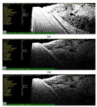
3.3 Method of dete rmining the pavement points
Figure 7. Determining the pavement points.
Where, (a)the original vehicle-borne laser point cloud with obvious slope; (b)Classical method with a more strict threshold and loopholes appeared in road boundary .(c) the pavement points using the method of this paper (refer to 2.3).(d) ground points based on (c) results with the same strict threshold.
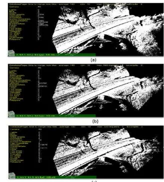
3.4 Processing of segment end of vehicle -borne laser point cloud
Figure 8. Segment end processing of vehicle-borne laser point cloud.
Where, (a)Points in two file; (b)Points in one file; (c)Filtering points after borrow some points, overlapped with the original points; (d) Only ground points.
In this case, 10 meters points are borrowed from the next file and 8 meters points are discard after the filtering. So there is 2 meters overlapped with the next ground point file. The purpose of borrowing point is to make sure that there are points under trees and prevent the points on the tree being taken as ground points.
4. 4. SUMMARY AND DISCUSSION
The application of the classical progressive triangulation method in the airborne point cloud is very successful, but the vehicle-borne laser point cloud is very different from the airborne point cloud. Vehicle-borne laser point cloud has larger density and uneven distribution. The density decreased significantly with distance from the pavement to both sides of the road, and a large part of the points hit the side of the surrounding features. The density of the vehicle-borne laser point cloud is large, however, it is not necessary to extract all the ground points in the practical applications, and the ground points just extracted by a certain space interval can achieve the project requirements. Therefore, this paper studies the extraction of the ground point, not the classification. First of all, the local vehicle-borne coordinate system is established by using the characteristics that the height from the vehicle-borne laser to pavement is fixed, and the relationship between the point cloud and the track line; Then, the points area is divided into a mesh according to the given resolution (cell size), and only the lowest points in every cell are picked up, so most non-ground points are discarded; In addition, it is very
easy to extract pavement points with good boundary through the convolution computation, and the pavement points will be good seeds for the subsequent filtering. Finally, a simple and practical method is presented to deal with tail faults caused by the inclined scanning surface. The above algorithm and method are validated by using the data in different regions. On the whole, the improved method in this paper is more suitable for the vehicle-borne point cloud filtering
ACKNOWLEDGEMENTS
This research was funded by: the Basic Research Fund of the Chinese Academy of Surveying and Mapping under Grant 7771726.
REFERENCES
LI Deren, J., 2006. Mobil Mapping Technology and Its Applications. GEOSPATIAL INFORMATION, 4(4), pp. 1-5 .
Sui Lichun, J., 2011. Filtering of Airborne LiDAR Point Cloud Data Based on Progressive TIN. Geomatics and Information Science of Wuhan University, 36(10), pp. 1159-1162.
Fang Huale, J., 2015. Object-oriented filtering method for mobile LiDAR point cloud. Science of Surveying and Mapping, 40(4), pp. 92-96.
Tian Maoyi, J., 2013. A Filtering Method of Vehicle-borne Laser Scanning Data. Journal of Geomatics Science and Technology,
30(6), pp. 593-596.
Guan Haiyan, J., 2007. On the Filtering Algorithm for Airborne Laser Scanning Data of Urban Area Based on Scanning Line.
Bulletin of Surveying and Mapping, (2007)12, pp. 9-13.
Axelesson, P., 2000. DEM from laser scanner data using adaptive TIN models[J]. International Archives of Photogrammetry and Remote Sensing, 33(B4/1), pp. 110-117.
LIHui, J., 2009. Advanced adaptive TIN filter for LIDAR point cloud data. Science of Surveying and Mapping, 34(3), pp.39-40.