P-ISSN : 2477-5029
E-ISSN : 2502-0498IJCCSIJCCS, Vol.x, No.x, July xxxx, pp. 1~5
ISSN: 1978-1520 ◼ 12
Orientation Effect on Statics and Natural Frequency of Cantilever Beam
Ardi Noerpamoengkas*1, Miftahul Ulum2, Ahmad Yusuf Ismail3
1,2,3Mechanical Engineering, Institut Teknologi Adhi Tama Surabaya, Surabaya e-mail: *1[email protected]
Abstrak
Analisis statis dan frekuensi penting untuk struktur, seperti batang kantilever, karena struktur tidak hanya dapat berfungsi untuk menyangga beban statis namun juga dinamis. Studi dan analisis statis dan frekuensi ini kebanyakan tidak melibatkan beban gravitasi. Penelitian yang ada mengenai pengaruh beban gravitasi mempelajari pengaruh posisi batang kantilever menggantung, horizontal, dan tegak. Arah gravitasi diaplikasi dengan menyudut terhadap batang kantilever, baik arah longitudinal maupun lateralnya, pada penelitian ini. Semakin tegak ke atas posisi batang kantilever semakin kecil frekuensi naturalnya. Displacement dan tegangan Von-Mises maksimum tertinggi saat kondisi horizontal dan sudut orientasi lateral 0°.
Perubahan posisi lateral batang kantilever tidak mempengaruhi frekuensi natural.
Kata kunci—Batang kantilever, beban gravitasi, frekuensi natural, statis, sudut orientasi
Abstract
Statics and frequency analyzes are important because the structure can support the static and dynamic loads. Most previous studies of statics and frequency did not involve the gravity load. The previous studies of gravity effect to the cantilever beam included the hanging, horizontal, and inverted positions. The gravity load direction is applied referred to the longitudinal and lateral beam directions in this study. The closer to the inverted position the smaller the natural frequency. The highest values of the maximum displacement and the maximum Von-Mises stress are happened if longitudinal position is horizontal and lateral orientation angle is 0°. The change of lateral orientation angle does not influence the natural frequency in this condition.
Keywords—Cantilever beam, gravity load, natural frequency, orientation angle, statics
1. INTRODUCTION
Static analysis is commonly used for analyzing the structure, such as a cantilever beam.
The analysis gives the useful information about the maximum displacement and the maximum equivalent Von-Mises stress. The longer the simply supported beam, the bigger the deflection [1]. The structure is safe if its equivalent Von-Mises stress is lower than its material yield strength [2]. The failure structure is very harmful to the supported mechanical or static system.
Frequency analysis is about the model natural frequencies and its mode shapes. The natural frequency of beam will be decreased by increasing its length [1]. Hole addition will also
decrease its natural frequency [3][4]. Notch addition will decrease the natural frequency of cantilever beam [5]. This phenomenon affects the beam vibrational transmissibility.
Approaching the natural frequency makes the high vibrational response [5].
Some researchers studied about the frequency of cantilever beam [6][7][8]. The larger beam dimension, such as length, width, and thick, gives the higher natural frequency. The high value of modulus of elasticity also gives the high natural frequency. Otherwise, the high value of density gives the low one. The cross-section model of beam with high inertia gives the high natural frequency and low mode shape deflection.
Gravity load influences the natural frequency of the structure [9][10][11]. The structure is on three conditions, vertical-inverted, horizontal, and vertical-hanging. Inverted position gives the lowest natural frequency. Hanging position gives the highest one. The hung cantilever beam was studied its transmissibility and natural frequency with notch addition [5].
Some researchers used the simulation software for statics and frequency analysis, such as ANSYS [1][12][13], COMSOL Multiphysics [14], NASTRAN [9], and Autodesk Inventor [3][4]. The more number of model elements the better simulation results [14]. However, the increasing number of elements makes the simulation process duration longer.
However, most researchers studied the statics and the natural frequency of beam by using simulation without gravity load [6][7][8]. The inclined angles between hanging, horizontal, and inverted positions have not been studied its effect on the natural frequency of beam yet [9]. Therefore, the orientation angles are referred to longitudinal and lateral beam positions in this research. The gravity load is applied to the model. This study is using the simulation method with the certain number of elements and nodes. The frequency analysis is simulated until 3rd natural frequency.
2. METHODOLOGY
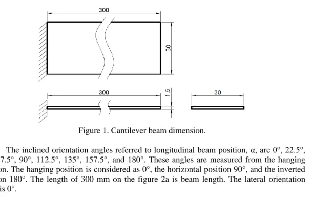
The model is a cantilever beam with rectangular cross-section, the thick of 1.5 mm, the width of 30 mm, and the length of 300 mm. The material is Aluminum 1100-O with isotropic mechanical behavior, Young’s modulus of 107 psi, Poisson’s ratio of 0.33, shear modulus of 3,700 ksi, yield strength of 5,000 psi, tensile strength of 13,000 psi, and density of 0.098 lb/in3.
Figure 1. Cantilever beam dimension.
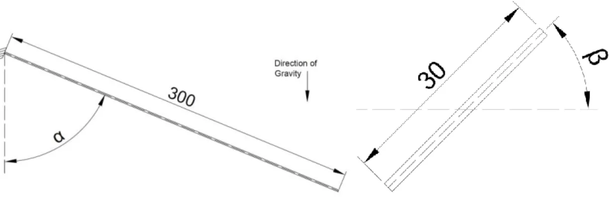
The inclined orientation angles referred to longitudinal beam position, α, are 0°, 22.5°, 45°, 67.5°, 90°, 112.5°, 135°, 157.5°, and 180°. These angles are measured from the hanging position. The hanging position is considered as 0°, the horizontal position 90°, and the inverted position 180°. The length of 300 mm on the figure 2a is beam length. The lateral orientation angle is 0°.
The inclined orientation angles referred to lateral beam position, β, are 0°, 22.5°, 45°, 67.5°, and 90°. The gravity load direction inclines to the width direction. The angle is 0° if the gravity load direction is perpendicular to the width direction. The length of 30 mm on the figure 2b is beam width. The longitudinal orientation angle is 90°.
(a) (b) Figure 2. Orientation angle of beam.
This study is using Autodesk Inventor simulation. The number of mesh elements is 128,706 elements. The number of nodes is 216,795 nodes. The model is fix constrained at one end face. Computing preload mode is used for the analyzes with the gravity of 9,810 mm/s2. The simulation results are maximum displacement, maximum Von-Mises stress, 1st natural frequency, 2nd natural frequency, and 3rd natural frequency. The mesh view in Figure 3 is in longitudinal angle of 90° and lateral angle of 0°.
Figure 3. Mesh view.
3. RESULTS AND DISCUSSION
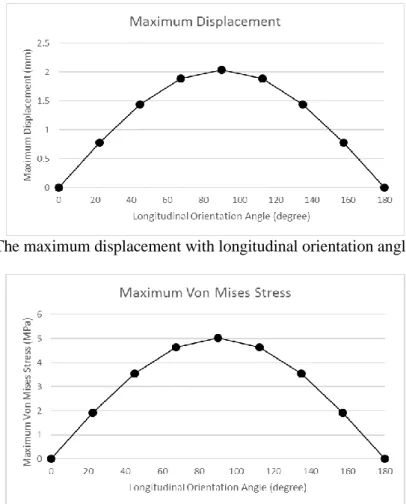
In the horizontal position, the cantilever beam has the highest value of the maximum displacement and the maximum Von-Mises stress. The maximum displacement value is 2.042 mm. The maximum Von-Mises stress value is 5.017 MPa. In the hanging and inverted positions, the cantilever beam has the same lowest values. The maximum displacement value is 0.00001724 mm. The maximum Von-Mises stress value is 0.01739 mm. These conditions are happened because the beam cross-section inertia factor in lateral load, such as in horizontal
condition, gives less contribution to the beam strength than the beam cross-section area factor in axial load. The beam cross-section inertia in this load direction is low because the beam thick is too lower than its width or 1/20 to its width. The minimum safety factor is 6.87 so it is safe in static criterion.
Figure 4. The maximum displacement with longitudinal orientation angle variation.
Figure 5. The maximum Von-Mises stress with longitudinal orientation angle variation.
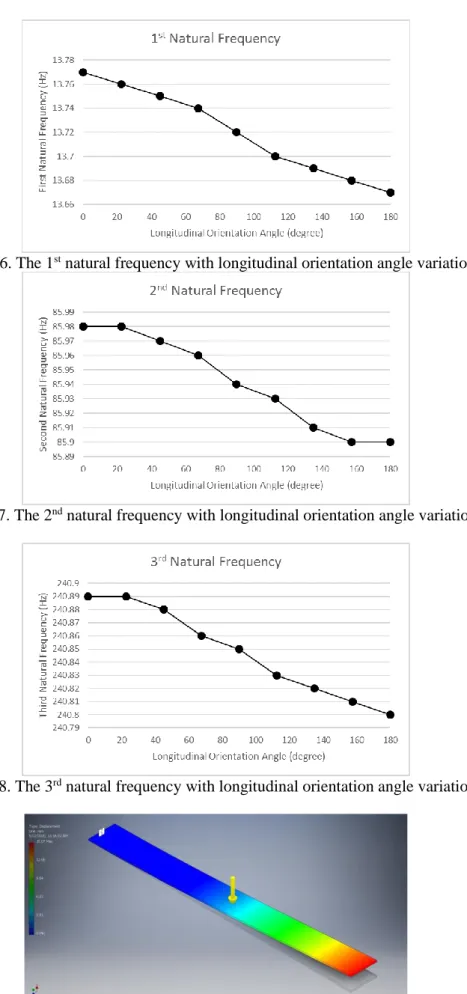
The closer to the inverted position the smaller the natural frequency. This trend is happened to the 1st, 2nd, and 3rd natural frequencies. In the hanging position, the 1st natural frequency is 13.77 Hz, the 2nd one 85.98 Hz, and the 3rd one 240.89 Hz. In the horizontal position, the 1st natural frequency is 13.72 Hz, the 2nd one 85.94 Hz, and the 3rd one 240.85 Hz.
In the inverted position, the 1st natural frequency is 13.67 Hz, the 2nd one 85.9 Hz, and the 3rd one 240.8 Hz. This trend matches the trend from the previous study [9].
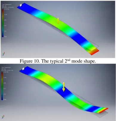
The mode shapes have the same typical shape and maximum displacement. The typical mode shape in each natural frequency condition can be seen on the Figure 9-11. The maximum displacement is about 15.08 mm in the 1st, 2nd, and 3rd mode shapes.
Figure 6. The 1st natural frequency with longitudinal orientation angle variation.
Figure 7. The 2nd natural frequency with longitudinal orientation angle variation.
Figure 8. The 3rd natural frequency with longitudinal orientation angle variation.
st
Figure 10. The typical 2nd mode shape.
Figure 11. The typical 3rd mode shape.
Table 1. Study results with lateral orientation angle variation.
Lateral Maximum Maximum 1s t 2nd 3rd
Orientation Von Mises Stress Displacement Natural Frequency Natural Frequency Natural Frequency
(degree) (Mpa) (mm) (Hz) (Hz) (Hz)
0 5.017 2.042 13.72 85.94 240.85
22.5 4.64 1.887 13.72 85.94 240.85
45 3.556 1.444 13.72 85.94 240.85
67.5 1.944 0.7814 13.72 85.94 240.85
90 0.4096 0.005236 13.72 85.94 240.85
Figure 12. The maximum displacement with lateral orientation angle variation.
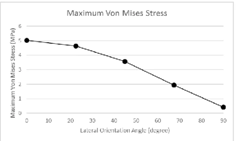
Figure 13. The maximum Von-Mises stress with lateral orientation angle variation.
The closer to the lateral orientation angle of 90° the lower the maximum displacement and Von-Mises stress. The maximum displacement value is 2.042 mm in angle of 0° and 0.005236 mm in angle of 90°. The maximum Von-Mises stress value is 5.017 MPa in angle of 0°, and 0.4096 MPa in angle of 90°. The highest values of maximum displacement and Von- Mises stress values are in the lateral orientation angle of 0° because the beam has the lowest inertia in this condition.
The change of lateral orientation angle does not influence the natural frequencies and its mode shapes in these various conditions. The maximum displacement in each mode shape is about 15.08 mm. It has the same value with the value in the various longitudinal orientation angle conditions. The typical mode shapes have the configuration as Figure 9-11. The natural frequency with no gravity load condition is same with the value of these orientation conditions.
It is occurred because they have the same tendency of the mode shape. The maximum displacement is only occurred in lateral direction of beam thick. The gravity load does not influence the natural frequency in this condition. It is worth considering the effect of other parameter that might affect the value significantly.
This study can consider the beam orientation angle that is according to the need as a support structure. The worst condition for the static aspect is the longitudinal angle of 90° and the lateral angle of 0° condition. The hanging position is the best condition for getting the highest natural frequency. The hanging position and the lateral angle of 0° condition can be considered as the best condition for the support of the static and dynamic loads.
4. CONCLUSION
The closer to the inverted position the lower the natural frequency in the various longitudinal orientation angle conditions. The highest value of the maximum displacement and the maximum Von-Mises stress is in the longitudinal angle of 90° and the lateral angle of 0°
condition. The change of lateral orientation angle does not influence the natural frequencies and its mode shapes in these various conditions. The hanging position and the lateral angle of 0°
condition can be considered as the best condition for the support of the static and dynamic loads.
ACKNOWLEDGEMENT
The authors would like to thank Institut Teknologi Adhi Tama Surabaya and Universitas Teuku Umar for supporting the research and this paper publication.
REFERENCES
[1] M. R. Usal, M. Usal, and Ü. Esendemir, “Static and Dynamic Analysis of Simply Supported Beams,” J. Reinf. Plast. Compos., vol. 27, no. 3, pp. 263–276, Feb. 2008.
[2] M. Awwaluddin and T. P. Soemardi, “ANALISIS TEGANGAN STATIK DAN DINAMIK PADA PERANCANGAN DAN PENGEMBANGAN STRUKTUR BODI MONORAIL PRODUKSI PT. MBW MENGGUNAKAN FINITE ELEMENT ANALYSIS (ANSYS),” in Seminar Universitas Indonesia, 2013.
[3] A. Y. Ismail, A. Noerpamoengkas, and S. I. F. S. Zakaria, “Effect of Micro-holes Addition on the Natural Frequency and Mode Shape of Perforated Plates,” J. Adv. Res.
Appl. Sci. Eng. Technol., vol. 11, no. 1, pp. 1–6, 2018.
[4] A. Y. Ismail, M. Ulum, and A. Noerpamoengkas, “PENGARUH DIAMETER
LUBANG, RASIO PERFORASI DAN SAMBUNGAN ANTAR PANEL TERHADAP FREKUENSI NATURAL PANEL BERLUBANG GANDA,” Pros. Semin. Nas. Sains dan Teknol. Terap., pp. 413–418, Sep. 2018.
[5] A. Noerpamoengkas, M. Ulum, and N. Mahfoudz, “Studi Eksperimental Pengaruh Posisi dan Kedalaman Takikan U Terhadap Frekuensi Natural dan Respon Getaran pada Batang Kantilever Menggantung | Noerpamoengkas | Prosiding Seminar Nasional Sains dan Teknologi Terapan,” in Prosiding Seminar Nasional Sains dan Teknologi Terapan, 2019, pp. 367–372.
[6] R. Raj, P. K. Sinha, and E. V. Prakash, “Modelling , Simulation and Analysis of Cantilever Beam of Different Material By Finite Element Method , Ansys & Matlab,”
Int. J. Eng. Res. Gen. Sci., 2015.
[7] V. Dive, M. Bhosale, V. Chavan, and N. Durugkar, “Analysis of Natural Frequencies of Cantilever Beam Using Ansys,” Int. Res. J. Eng. Technol., vol. 4, no. 5, pp. 2724–2728, 2017.
[8] V. Kumar, K. Kumar Singh, and S. Gaurav, “Analysis of Natural Frequencies for Cantilever Beam with I-and T-Section Using Ansys,” Int. Res. J. Eng. Technol., vol. 2, pp. 1013–1020, Sep. 2015.
[9] J. W. Jones, R. E. Nickell, and W. Bulat, “The Effects of Gravity on Structural Vibration,” in Volume 8: Seismic Engineering, 2013, p. V008T08A044.
[10] L. N. Virgin, S. T. Santillan, and D. B. Holland, “Effect of gravity on the vibration of vertical cantilevers,” Mech. Res. Commun., vol. 34, no. 3, pp. 312–317, Apr. 2007.
[11] D.-O. Kim, W.-S. Choi, K.-B. Park, and W.-J. Lee, “Natural Frequency Shift of a Graphite Column by Gravity,” in Transactions, SMiRT 19, 2007, p. K11/2.
[12] G. N. Prasanna, “Static Analysis of aTapered Beam Using Excel and Ansys,” Int. J. Sci.
Res., vol. 7, no. 4, pp. 282–285, 2018.
[13] L. Jakubovičová, A. Sapietová, and J. Moravec, “Static analysis of transmission tower beam structure,” MATEC Web Conf., vol. 244, p. 01011, 2018.
[14] K. A. Oladejo, R. Abu, and O. A. Bamiro, “Model for Deflection Analysis in Cantilever Beam,” Eur. J. Eng. Res. Sci., vol. 3, no. 12, pp. 60–66, Dec. 2018.