DESIGN OF 16 ACTUATORS FOR 3D MASSIVE
PARALLEL ROBOTS (3D-MPRs)
Felix Pasila, IEEE Member Hans Natalius and Roche Alimin
Department of Electrical Engineering Department of Mechanical Engineering
Petra Christian University Petra Christian University
Surabaya, East Java 60236, Indonesia Surabaya, East Java 60236, Indonesia
[email protected] [email protected] and [email protected]
Abstract– In this paper, a novel sixteen parallel manipulator
with discrete control system is developed. An efficient method such as Inverse Static Analysis is employed to determine the state of each actuator on parallel manipulator when the position or force of manipulator is already known. The designing a parallel manipulator with actuators which are controlled discretely is a must because the mechanism will use artificial methods in dealing with the ISA problem.
The research method used are simulation software and hardware testing with the case of parallel manipulator with 16 actuators. Simulations with typical desired force inputs are presented and a good performance of the mechanism is obtained. The results showed that the parallel manipulator has the Root Mean Squared Error (RMSE) has less than 5%.
Index Terms - Parallel Manipulator, 16 parallel actuators, Inverse Static Analysis.
I. INTRODUCTION
Parallel manipulator is a manipulator that consists of a number of actuators which are arranged in parallel. In general, parallel manipulator mechanism consists of a combination of several joint, where the actuators that move the manipulator serves as a Prismatic joint. Parallel manipulator has been developed for a wide range of applications such as machine tool applications, motion simulators, and bio-mechanic applications.
In designing a parallel manipulator, Jacobian matrix is usually used. Jacobian matrix is a determinant matrix which is used to solve the inverse of a number of functions with certain variables and used in determining the solution of static analysis, kinematic and dynamic analysis of a parallel manipulator, which is in another words, apart from being used in designing parallel manipulators, the Jacobian matrix method is also used in developing the analogue control system of the aforementioned parallel manipulator. However, this method has its drawbacks because Jacobian matrix can only control a maximum number intelligence [1]. ISA method is expected to be used to control a parallel manipulator with more than six actuators.
In addition to analogue control, there is also discrete control where the actuators are assigned with a limited number of state. A manipulator with discrete control is intended to reduce the complexity of the procedure and to develop a robot without sensors. One example of discrete controlled manipulator is the Discrete Snake-like Robot [2-10].
Previous studies which are closely linked to the control of discrete parallel manipulator using artificial intelligence was conducted by Pasila [11]. This study focused on controlling the massive parallel manipulator using neuro-fuzzy method. The parallel manipulators used in the aforementioned research have 16 prismatic actuator with 16-SPS-3D mechanism. SPS means Spherical-Prismatic-Spherical. Actuators used are double action pneumatic actuators that require a number of directional control valves according to the number of actuators. Results obtained from this study is that the parallel manipulator twisted due to the way the actuators are arranged which are separated from each other.
Looking at the current development, there has been no parallel manipulator that has more than 6 actuators that are discretely controlled, resulting in the use Jacobian method that can only produce at maximum 6 outputs. For that, a parallel manipulator mechanism with more than 6 actuators needs to be designed according to the needs of Neural Network artificial intelligence system implementation as the ISA solution for the parallel manipulator.
The goal of this research is to design a parallel manipulator with more than 6 actuator for the need of the implementation of Neural Network. The second objective is to obtain a state approximation for each actuator to obtain efficient results with Root Mean Square (RMS) error of less than 10%.
II.RESEARCH METHODOLOGY
The research methodology in this study is divided into chapter A about the design of the parallel manipulator and sub-chapter B about data gathering.
A. Design of the Parallel Manipulator
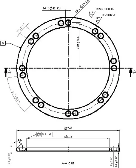
and the lower body are circular bodies that have different diameters. To determine the dimensions of the fixed body and the moving platform for the manipulator in this research, as well as the location of each actuator, trial and error method is used. Trial and error method was done with the help of simulation software using Solidworks Motion Study. This trial and error method was done to obtain dimensions of the fixed body and the moving platform to accommodate the actuator arrangement so that the manipulator will not experience an unexpected twist. There are several things that must be considered to determine whether the manipulator will experience a twist or not, in this case a parallel manipulator with more than 6 actuator, which are the number of actuators and actuator positions that will affect the dimension of the manipulator. The minimum number of actuators required in order to prevent a twist in the manipulator is 6 actuators, and the maximum number of actuators that can be used is limited only by the dimension specified for the manipulator. In this research, the number of actuator used was determined to be 16 actuators. In order to determine the position of each actuator, two parallel manipulator designs are used as reference, the Pasila manipulator and Stewart-Gough platform. Both of these designs were tested using Solidworks Motion Study software to test whether the manipulator will experience twist. From the test results with Solidworks Motion Study, it was known that the design of the 16 actuators manipulator will not experience twist if designed using the actuator position architecture based on the Stewart-Gough platform [12]. Specifications of both bodies can be seen in Table 1 and Table 2. The manipulator can be seen in Fig. 1. The technical drawing of the fixed body and the moving platform of the manipulator can be seen in Fig. 2 and Fig. 3.
TABLE I
SPECIFICATIONS OF THE MANIPULATOR FIXED BODY
Fixed Body
Material Aluminium 6061 -
Mass 8764.42 gr
Volume 3246082.03 mm3
Outer Circle Diameter 740 Mm
Joint Center Point Diameter 660 Mm
Inner Circle Diameter 596 Mm
TABLE II
SPECIFICATIONS OF THE MANIPULATOR MOVING PLATFORM
Moving platform
Material Aluminium 6061 -
Mass 6758.56 gr
Volume 2503170.76 mm3
Outer Circle Diameter 560 mm
Joint Center Point Diameter 500 mm
Inner Circle Diameter 400 mm
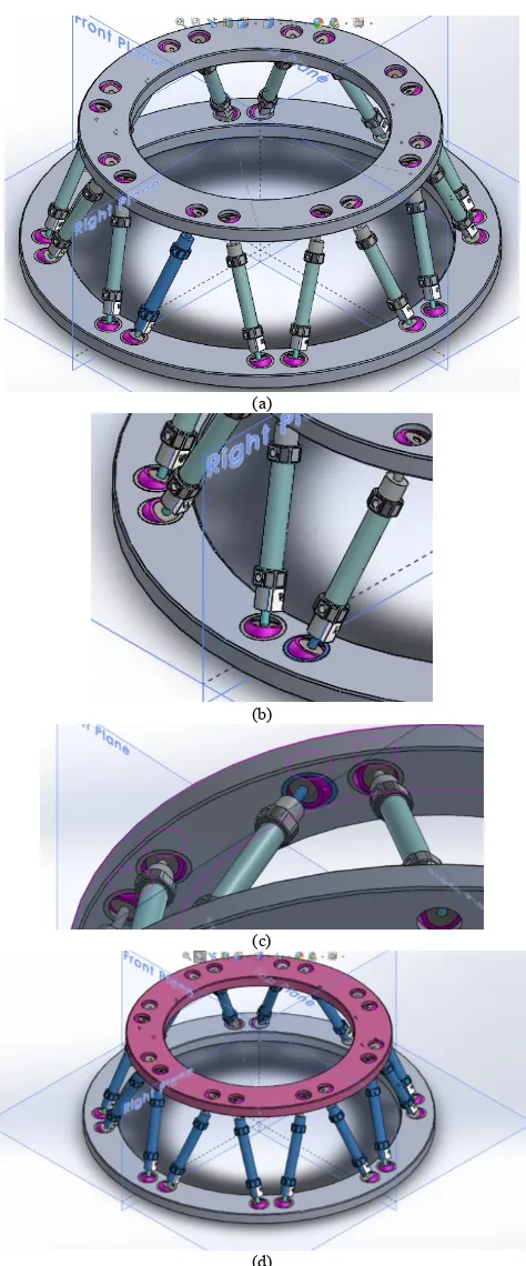
Fig. 1 Manipulator prototype using 16 discrete actuators.
Fig. 3 Technical Drawing of the Moving Platform of the Manipulator.
The parallel manipulator in this research has 16 prismatic actuators and uses a Spherical-Prismatic-Spherical (SPS) joint configuration. The Degree of Freedom calculation of this manipulator is described as following:
The Manipulator has to have 6 active DOFs: (1) The Manipulator consists of 2 rigid bodies which are connected by 16 actuators, where each of the actuators consists of 2 bodies. The amount of links in the system is:
(2)
The Manipulator has 2 types of joints, which are 16 prismatic actuators and 32spherical joints. The amount of joints in the system is:
(3)
In practice, each of the actuators used has 2 DOFs, which consist of 1 translational motion DOF and 1 rotational motion DOF. Each of the spherical joints used has 3 DOFs. The amount of DOFs in the system is:
(4)
The amount of DOFs in the mechanism is:
(5)
From the calculation, it can be seen that the manipulator designed in this research has 38 DOFs where 32 DOFs are considered to be passive DOFs. Because of this, the mechanism is considered to be redundant.
The parallel manipulator used has 16 pairs of spherical joint and 16 pneumatic actuators which serve as prismatic joints. Actuators connect the moving platform and the fixed body using the spherical joints to form SPS construction. Actuators used are JELPC dual action type pneumatic actuators with 70 mm stroke and 12 mm bore and can work at air pressure range of 1-9 kg/mm2. Both ends of the actuators are connected to hubs with 25 mm diameter and 21 mm height which are made of ST60 steel. The hubs serve to connect the actuator with the spherical joints. The hub and the spherical joint are then locked by using a pair of plates with a thickness of 1 mm 30 mm diameter made of ST42 steel. The technical drawing of the hub can be seen in Fig. 4.
Fig. 4 Technical Drawing of the Hub used in the Manipulator.
As a drive system for the manipulator, a compressor, and 8 pieces of 5/3 solenoid valve are used, which are operated by using 2 pieces of Programmable Logic Controller (PLC) Siemens S7-200 PLC where each PLC controls 4 valves. The pneumatic circuit and related PLC drawing are not explained in this paper.
B. Collecting Data via Solidworks Motion Study
calculate the mechanical error. 105 data were taken as samples in this mechanical testing. The bodies where the contact parameters are applied are shown in Fig. 5.
(a)
(b)
(c)
(d)
Fig. 5. Bodies That Were Given Contact Parameters (a) Contact Parameters between Actuator Casing and Piston (b) Contact Parameters between Actuator
and Spherical Joint on the Fixed Body (c) Contact Parameters between Actuator and Spherical Joint on the Moving Platform (d) Contact Parameters
between Actuator and the Moving Platform
III.RESULTS AND DISCUSSIONS
Fig. 6 shows graphs of data simulation results with a total of 819 data which are already sorted from the smallest to the largest value. The results are obtained using Solidworks Motion Study software.
(a)
(b)
(c)
Fig. 6. Data Graphs Showing Results Obtained by Simulation Using Computer Software (a) X axis coordinates obtained using simulation (b) Y axis coordinates obtained using simulation (c) Z axis coordinates obtained using
simulation.
the Y-axis the maximum value is 276.14 mm and the minimum value is 199.42 mm, and along the Z-axis the maximum value is 64.62 mm and the minimum value is -64.67mm. The graph for coordinates along the Y axis look different from other graphs due to the data value not being evenly distributed.
The parallel manipulator is planned to be controlled discretely using Neural Network as ISA solution for the manipulator. The performance of the discretely controlled manipulator is expected to resemble the analogue controlled manipulator. In addition, it can be seen that the position along X and Z axis closely resemble the value generated when using analogue controller. On the other hand, there is a fairly large deviation between the coordinates generated from the simulation with the software and the coordinates generated when using the analogue control observed along the Y axis which can be seen in the graph, where the position results obtained using the simulation along the Y axis jump at some point. As a result, it is possible that neural network might not work optimally as an ISA solution for the planned manipulator. The mechanical test data needs to be compared with the software simulation data to obtain mechanism error which is expressed as root mean square error (RMSE). Some data comparison samples between the position obtained by simulation using the Solidworks Motion Study software and position measurement results obtained by manipulator prototype testing can be seen in Table 3.
TABLE III
COMPARISON OF MANIPULATOR POSITION RESULTS BETWEEN SOFTWARE SIMULATION RESULT AND MANIPULATOR MEASUREMENT RESULT
It was found in some samples that the simulation result show that the reference point is located between 1 and 0 along X or Z axis, while the measurement shows that the accuracy of 1 mm, so it is not possible to accurately determine the position of the reference point. As a result, the data listed as the measurement result are the nearest coordinate obtained at the time of the measurement, in this case located on the X calculation, it can be seen that the mechanism RMSE is 5.87% along the X axis, 0.45% along the Y axis, and 6.05% along the Z axis, while the RMSE observed along the X, Y, and Z axis combined is 2.81%. The relatively small RMSE value along the combined axis can be obtained thanks to the relatively small RMSE value observed along the Y axis, which is only 0.45%. This means that the mechanism generates a relatively small of error even though the error along the X and Z axis exceeds 5%. Therefore, it can be said that although the construction of the manipulator is still not yet optimized, the 16 actuators parallel manipulator mechanism designed in this research is working well.
IV.CONCLUSIONS
representation of the analogue control, it is possible that the artificial intelligence will not work properly as the ISA solution to this manipulator in generating the desired position along the Y axis. However, this remains to be proven by means of implementing artificial intelligence as the ISA solution to discretely control the manipulator. The conclusion that can be drawn from this research based from the value of the RMSE is that the parallel manipulator 16 actuators are designed in this research works relatively well (average error below 5%) and can be used for artificial intelligence implementation.
REFERENCES
[1] Pasila F., “Inverse Static Analysis of Massive Parallel Arrays of Three
-State Actuators via Artificial Intelligence”, PhD Dissertation, University
of Bologna, 2013.
[2] Pieper D.L., “The Kinematics of Manipulators under Computer Control”, PhD Thesis, Stanford University, Stanford, CA, 1968.
[3] Roth B., Rastegar J. and Sheinman V., “On the Design of Computer
Controlled Manipulators”, First CISM-IFTMM Symposium on Theory and Practice of Robots and Manipulators, pp. 93-113, 1973.
[4] Chirikjian G. S.,”A Binary Paradigm for Robotic Manipulators”, Proceedings of the 1994 IEEE International Conference on Robotics and Automation, pp. 3063-3069, 1994.
[5] Chirikjian G.S., Lees D.S., “Inverse Kinematics of Binary Manipulators with Applications to Service Robotics”, Proceedings of the 1995 IEEE International Conference on Intelligent Robots and Systems, pp. 65-71, 1995.
[6] Lees D.S., Chirikjian G.S., “A Combinatorial Approach to Trajectory
Planning for Binary Manipulators”, Proceedings of the 1996 IEEE
International Conference on Robotics and Automation, pp. 2749-2754, 1996.
[7] Chirikjian G. S.,”Inverse Kinematics of Binary Manipulators Using a
Continuum Model”, Journal of Intelligent and Robotic Systems, vol.19,
pp.5-22, 1997.
[8] Ebert-Uphoff I., Chirikjian G.S., “Inverse Kinematics of Discretely Actuated Hyper-Redundant Manipulators Using Workspace Densities”, Proceedings of the 1996 IEEE International Conference on Robotics and Automation, pp. 139-145, 1996.
[9] Suthakorn J. and Chirikjian G. S.,”A New Inverse Kinematic Algorithm
for Binary Manipulators with Many Actuators”, Advanced Robotics, vol.
15, n. 2, pp. 225-244, 2001.
[10] Sujan V.A., Lichter D., Dubowsky S., “Lightweight Hyper-Redundant
Binary Elements for planetary Exploration Robots”, 2001 IEEE/ASME
International Conference on Advanced Intelligent Mechatronics, pp. 1273-1278, 2001.
[11] Pasila F., Alimin R., Natalius H., “Neuro-Fuzzy Architechture of the 3D
Model of Massive Parallel Actuators”, ARPN Journal of Engineering and
Applied Sciences, vol. 9, pp. 2900-2905, 2014.