Lampiran :
Data Sheet Solid State Timer
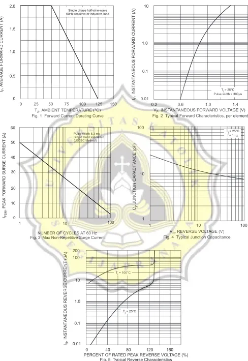
Mosfet IRF 730
Solid-state Timer
H3CR
1
Solid-state Timer
H3CR
DIN 48
×
48-mm Multifunctional Timer Series
• Conforms to EN61812-1 and IEC60664-1 4 kV/2 for Low
Voltage, and EMC Directives.
• Approved by UL and CSA.
• Lloyds/NK approvals.
• Six-language instruction manual provided.
■
Broad Line-up of H3CR Series
Contents
Solid-state Timer
H3CR-A... 2
H3CR-F ... 24
H3CR-G ... 30
H3CR-H ... 37
Common to ALL Timers
Operation ... 45Accessories... 47
Safety Precautions ... 51
H3CR
Multifunctional Timer
Twin Timer
Star-delta Timer
Power OFF-delay Timer
H3CR-G
H3CR-F
Note: H3CR-AS, H3CR-A8S: Transistor output models 11-pin model
8-pin model
11-pin model
8-pin model
8-pin model
8-pin model 11-pin model
H3CR-A
H3CR-A
H3CR-AS
H3CR-AP
H3CR-A8
H3CR-A8S
H3CR-A8E
8-pin with instantaneous contact output modelH3CR-F
H3CR-FN
H3CR-F-300
H3CR-FN-300
H3CR-F8
H3CR-F8N
H3CR-F8-300
H3CR-F8N-300
H3CR-G8L
H3CR-G8EL
H3CR-HRL
H3CR-H8L
H3CR-H8RL
H3CR-H
Solid-state Multi-functional Timer
H3CR-A
DIN 48
×
48-mm State-of-the-art
Multifunctional Timer
• A wider power supply range reduces the number of timer
mod-els kept in stock.
• A wide range of applications through six or four operating
modes.
• Reduced power consumption.
(Except for H3CR-A8E)
• Enables easy sequence checks through instantaneous outputs
for a zero set value at any time range.
• Length, when panel-mounted with a Socket, of 80 mm or less.
• Time Setting Rings enable consistent settings and limit the
set-ting range.
• Panel Covers enable various panel designs.
• PNP input models available.
• Rich variety of inputs: Start, reset, and gate functions (11-pin
models and -AP models)
Model Number Structure
■
Model Number Legend
Note:This model number legend includes combinations that are not available. Before ordering, please check the List of Models on page 3 for avail-ability.
1. Number of Pins
None: 11-pin models 8: 8-pin models
2. Input Type for 11-pin Models
None: No-voltage input (NPN type) P: Voltage input (PNP type)
3. Output
None: Relay output (DPDT)
S: Transistor output (NPN/PNP universal use)
E: Relay output (SPDT) with instantaneous relay output (SPDT)
4. Suffix
300: Dual mode models (signal ON/OFF-delay and one-shot) 301: Double time scale (range) models (0.1 s to 600 h)
5. Supply Voltage
H3CR-A
@ @ @
-
@ @
Solid-state Multi-functional Timer
H3CR-A
3
Ordering Information
■
List of Models
11-pin Models
8-pin Models
Supply voltage
Note: 1. Specify both the model number and supply voltage when ordering. Example: H3CR-A 100-240AC/100-125DC
2. The operating modes are as follows
A: ON-delay D: Signal OFF-delay B: Flicker OFF start E: Interval
B2: Flicker ON start G: Signal ON/OFF-delay C: Signal ON/OFF-delay J: One-shot
Output Supply voltage Input type Time range Operating mode
(See note 2)
Model (See note 1.) Contact 100 to 240 VAC (50/60 Hz)/
100 to 125 VDC
No-voltage input 0.05 s to 300 h Six multi-modes: A, B, B2, C, D, E
H3CR-A
24 to 48 VAC (50/60 Hz)/ 12 to 48 VDC
100 to 240 VAC (50/60 Hz)/ 100 to 125 VDC
Dual-modes: G, J H3CR-A-300
24 to 48 VAC (50/60 Hz)/ 12 to 48 VDC
100 to 240 VAC (50/60 Hz)/ 100 to 125 VDC
Voltage input Six multi-modes: A, B, B2, C, D, E
H3CR-AP
24 to 48 VAC (50/60 Hz)/ 12 to 48 VDC
100 to 240 VAC (50/60 Hz)/ 100 to 125 VDC
No-voltage input 0.1 s to 600 h H3CR-A-301
24 to 48 VAC (50/60 Hz)/ 12 to 48 VDC
Transistor (Photocoupler)
24 to 48 VAC (50/60 Hz)/ 12 to 48 VDC
0.05 s to 300 h H3CR-AS
Output Supply voltage Input type Time range Operating mode
(See note 2)
Model (See note 1.) Contact 100 to 240 VAC (50/60 Hz)/
100 to 125 VDC
No-input available 0.05 s to 300 h Four multi-modes: A, B2, E, J
(Power supply start)
H3CR-A8
24 to 48 VAC (50/60 Hz)/ 12 to 48 VDC
100 to 240 VAC (50/60 Hz)/ 100 to 125 VDC
0.1 s to 600 h H3CR-A8-301
24 to 48 VAC (50/60 Hz)/ 12 to 48 VDC
Transistor (Photocoupler)
24 to 48 VAC (50/60 Hz)/ 12 to 48 VDC
0.05 s to 300 h H3CR-A8S
Time-limit contact and instantaneous contact
100 to 240 VAC (50/60 Hz)/ 100 to 125 VDC
H3CR-A8E
■
Accessories (Order Separately)
Note: 1. Y92A-48G is a finger safe terminal cover which is attached to the P3G-08 or P3GA-11 Socket.
2. The Time Setting Ring and Panel Cover are sold together.
3. Hold-down Clips are sold in sets of two.
Specifications
■
General
Name/specifications Models
Flush Mounting Adapter Y92F-30
Y92F-73 Y92F-74
Mounting Track 50 cm (l) × 7.3 mm (t) PFP-50N
1 m (l) × 7.3 mm (t) PFP-100N
1 m (l) × 16 mm (t) PFP-100N2
End Plate PFP-M
Spacer PFP-S
Protective Cover Y92A-48B
Track Mounting/
Front Connecting Socket
8-pin P2CF-08
8-pin, finger safe type P2CF-08-E
11-pin P2CF-11
11-pin, finger safe type P2CF-11-E
Back Connecting Socket 8-pin P3G-08
8-pin, finger safe type P3G-08 with Y92A-48G (See note 1)
11-pin P3GA-11
11-pin, finger safe type P3GA-11 with Y92A-48G (See note 1)
Time Setting Ring Setting a specific time Y92S-27
Limiting the setting range Y92S-28
Panel Cover (See note 2) Light gray (5Y7/1) Y92P-48GL
Black (N1.5) Y92P-48GB
Medium gray (5Y5/1) Y92P-48GM
Hold-down Clip (See note 3) For PL08 and PL11 Sockets Y92H-7
For PF085A Socket Y92H-8
Item H3CR-A/-AS H3CR-AP H3CR-A8/-A8S H3CR-A8E
Operating mode A: ON-delay B: Flicker OFF start B2: Flicker ON start C: Signal ON/OFF-delay D: Signal OFF-delay E: Interval
G: Signal ON/OFF-delay (Only for H3CR-A-300) J: One-shot (Only for H3CR-A-300)
A: ON-delay (power supply start) B2: Flicker ON start (power supply start) E: Interval (power supply start) J: One-shot (power supply start)
Pin type 11-pin 8-pin
Input type No-voltage input Voltage input
---Time-limit output type H3CR-A/-A8/-AP: Relay output (DPDT)
H3CR-AS/-A8S: Transistor output (NPN/PNP universal)*
Solid-state Multi-functional Timer
H3CR-A
5
■
Time Ranges
Note:When the time setting knob is turned below “0” until the point where the time setting knob stops, the output will operate instantaneously at all time range settings.
Standard (0.05-s to 300-h) Models
Double (0.1-s to 600-h) Models
■
Ratings
Note: 1. DC ripple rate: 20% max. if the power supply incorporates a single-phase, full-wave rectifier.
2. Do not use an inverter output as the power supply. Refer to Power Supplies in Safety Precautions for All Timers on page 51 for details.
3. Models with 24-to-48-VAC or 12-to-48-VDC power supply have inrush current. Caution is thus required when turning ON and OFF power to the Timer with a non-contact output from a device such as a sensor. (Models with an inrush current of approximately 50 mA and a 24-VDC power supply are available (the H3CR-A-302 and H3CR-A8-302).)
4. The values are for when the terminals 2 and 7 and terminals 10 and 6 are short-circuited, and include the consumption current of the input circuit.
5. Refer to Power Supplies in Safety Precautions for All Timers on page 51 when using the Timer together with a 2-wire AC proximity sensor.
Time unit s (sec) min (min) h (hrs) ×10 h (10 h)
Full scale setting
1.2 0.05 to 1.2 0.12 to 1.2 1.2 to 12
3 0.3 to 3 3 to 30
12 1.2 to 12 12 to 120
30 3 to 30 30 to 300
Time unit s (sec) min (min) h (hrs) ×10 h (10 h)
Full scale setting
2.4 0.1 to 2.4 0.24 to 2.4 2.4 to 24
6 0.6 to 6 6 to 60
24 2.4 to 24 24 to 240
60 6 to 60 60 to 600
Rated supply voltage (See notes 1, 2, and 5.) 100 to 240 VAC (50/60 Hz)/100 to 125 VDC, 24 to 48 VAC (50/60 Hz)/12 to 48 VDC (24 to 48 VAC/VDC for H3CR-A8E) (See note3.)
Operating voltage range 85% to 110% of rated supply voltage (90% to 110% at 12 VDC)
Power reset Minimum power-opening time: 0.1 s
Input No-voltage Input
ON impedance: 1 kΩ max. ON residual voltage: 1 V max. OFF impedance: 100 kΩ min. Voltage Input
Max. permissible capacitance between inputs lines (terminals 6 and 7): 1,200 pF Load connectable in parallel with inputs (terminals 6 and 7).
• 100 to 240 VAC/100 to 125 VDC
High (logic) level: 85 to 264 VAC/85 to 137.5 VDC Low (logic) level: 0 to 10 VAC/0 to 10 VDC • 24 to 48 VAC/12 to 48 VDC
High (logic) level: 20.4 to 52.8 VAC/10.8 to 52.8 VDC Low (logic) level: 0 to 2.4 VAC/0 to 1.2 VDC
Power consumption H3CR-A/-A8
• 100 to 240 VAC/100 to 125 VDC (When at 240 VAC, 60 Hz)
Relay ON: approx. 2.0 VA (1.6 W) Relay OFF: approx. 1.3 VA (1.1 W) • 24 to 48 VAC/12 to 48 VDC
(When at 24 VDC)
Relay ON: approx. 0.8 W Relay OFF: approx. 0.2 W H3CR-AP (See note 3)
• 100 to 240 VAC/100 to 125 VDC (When at 240 VAC, 60 Hz)
Relay ON: approx. 2.5 VA (2.2 W) (See note 4.) Relay OFF: approx. 1.8 VA (1.7 W) (See note 4.) • 24 to 48 VAC/12 to 48 VDC
(When at 24 VDC)
Relay ON: approx. 0.9 W (See note 4.) Relay OFF: approx. 0.3 W (See note 4.) H3CR-A8E
• 100 to 240 VAC/100 to 125 VDC (When at 240 VAC, 60 Hz)
Relay ON/OFF: approx. 2 VA (0.9 W) • 24 to 48 VAC/VDC
(When at 24 VDC)
Relay ON/OFF: approx. 0.9 W H3CR-AS/-A8S
• 24 to 48 VAC/12 to 48 VDC (When at 24 VDC)
Output ON: 0.3 W Output OFF: 0.2 W
Control outputs Time limit contacts: 5 A at 250 VAC/30 VDC, 0.15 A at 125 VDC, resistive load (cosφ = 1) Transistor output: Open collector (NPN/PNP), 100 mA max. at 30 VDC max.,
residual voltage: 2 V max.
■
Characteristics
Note: 1. The value is ±5% FS +100 ms to −0 ms max. when the C, D, or G mode signal of the H3CR-AP is OFF.
2. Refer to the Life-test Curve.
Accuracy of operating time
±0.2% FS max. (±0.2%±10 ms max. in a range of 1.2 s)
Setting error ±5% FS ±50 ms (See note 1)
Reset time Min. power-opening time: 0.1 s max.
Min. pulse width: 0.05 s (H3CR-A/-AS)
Reset voltage 10% max. of rated supply voltage
Influence of voltage ±0.2% FS max. (±0.2%±10 ms max. in a range of 1.2 s)
Influence of temperature ±1% FS max. (±1%±10 ms max. in a range of 1.2 s)
Insulation resistance 100 MΩ min. (at 500 VDC)
Dielectric strength 2,000 VAC (1,000 VAC for H3CR-A@S), 50/60 Hz for 1 min (between current-carrying metal parts and exposed non-current-carrying metal parts)
2,000 VAC (1,000 VAC for H3CR-A@S), 50/60 Hz for 1 min (between control output terminals and operating circuit) 2,000 VAC, 50/60 Hz for 1 min (between contacts of different polarities)
1,000 VAC, 50/60 Hz for 1 min (between contacts not located next to each other)
2,000 VAC, 50/60 Hz for 1 min (between input and control output terminals and operation circuit) for H3CR-AP
Impulse withstand voltage
3 kV (between power terminals) for 100 to 240 VAC/100 to 125 VDC, 1 kV for 24 to 48 VAC/12 to 48 VDC
4.5 kV (between current-carrying terminal and exposed non-current-carrying metal parts) for 100 to 240 VAC/100 to 125 VDC, 1.5 kV for 24 to 48 VAC/12 to 48 VDC and 24 to 48 VAC/VDC
Noise immunity ±1.5 kV (between power terminals) and ±600 V (between no-voltage input terminals), square-wave noise by noise simulator (pulse width: 100 ns/1 µs, 1-ns rise)
Static immunity Malfunction: 8 kV Destruction: 15 kV
Vibration resistance Destruction: 10 to 55 Hz with 0.75-mm single amplitude each in 3 directions for 2 hours each Malfunction: 10 to 55 Hz with 0.5-mm single amplitude each in 3 directions for 10 minutes each
Shock resistance Destruction: 1,000 m/s2 3 times each in 6 directions
Malfunction: 100 m/s2 3 times each in 6 directions
Ambient temperature Operating: −10°C to 55°C (with no icing) Storage: −25°C to 65°C (with no icing)
Ambient humidity Operating: 35% to 85%
Life expectancy Mechanical: 20,000,000 operations min. (under no load at 1,800 operations/h)
Electrical: 100,000 operations min. (5 A at 250 VAC, resistive load at 1,800 operations/h) (See note 2)
EMC (EMI) EN61812-1
Emission Enclosure: EN55011 Group 1 class A Emission AC Mains: EN55011 Group 1 class A (EMS) EN61812-1
Immunity ESD: IEC61000-4-2: 6 kV contact discharge (level 3) 8 kV air discharge (level 3)
Immunity RF-interference from AM Radio Waves: IEC61000-4-3: 10 V/m (80 MHz to 1 GHz) (level 3) Immunity RF-interference from Pulse-modulated Radio Waves: IEC61000-4-3: 10 V/m (900±5 MHz) (level 3) Immunity Conducted Disturbance: IEC61000-4-6: 10 V (0.15 to 80 MHz) (level 3)
Immunity Burst: IEC61000-4-4: 2 kV power-line (level 3) 2 kV I/O signal-line (level 4) Immunity Surge: IEC61000-4-5: 1 kV line to line (level 3)
2 kV line to ground (level 3)
Case color Light gray (Munsell 5Y7/1)
Degree of protection IP40 (panel surface)
Solid-state Multi-functional Timer
H3CR-A
7
■
Life-test Curve
10,000
5,000
1,000
500
100
Load current (A)
30 VDC L/R = 7 ms
250 VAC (cosφ = 0.4)
Switching oper
ations (x 10
3)
250 VAC/30 VDC (cosφ = 1)
Reference: A maximum current of 0.15 A can be switched at 125 VDC (cosφ = 1) and a maximum current of 0.1 A can be switched if L/R is 7 ms. In both cases, a life of 100,000 operations can be expected.
Connections
■
Block Diagrams
H3CR-A/AS
AC (DC) input
Output circuit
Reset input, start input, and gate input Input circuit Power supply
circuit
Oscillation circuit
Counting circuit Zero setting
detection circuit
Time range/ unit selectors
Operating mode selector
Indicator circuit
Power-ON indicator
Output-ON indicator
H3CR-AP
AC (DC) input
Output circuit
Start Input circuit Power supply
circuit
Zero setting detection circuit
Oscillation circuit
Counting circuit Time range/ unit selectors
Operating mode selector
Indicator circuit
Power-ON indicator
Solid-state Multi-functional Timer
H3CR-A
9
■
I/O Functions
Note:H3CR-AP incorporates start input only.
H3CR-A8/A8S
AC (DC) input
Output circuit Power supply
circuit
Zero setting detection circuit
Oscillation circuit
Counting circuit Time range/ unit selectors
Operating mode selector
Indicator circuit
Power-ON indicator
Output-ON indicator
H3CR-A8E
AC (DC) input
Output circuit Power supply
circuit
Zero setting detection circuit
Oscillation circuit
Counting circuit Time range/ unit selectors
Operating mode selector
Indicator circuit
Power-ON indicator
Output-ON indicator
Instantaneous output circuit
Inputs (for -A/ -AS models)
Start Starts time-measurement.
Reset Interrupts time-measurement and resets time-measurement value. No time-measurement is made and control output is OFF while the reset input is ON.
Gate Prohibits time-measurement.
■
Terminal Arrangement
Note:The delayed contact of conventional Timers was indicated as
The contact symbol of the H3CR-A is indicated as because its operating mode is six multi-modes (four multi-modes for the H3CR-A8).
11-pin Models
Note:Terminals 1, 3, 4, and 8 are empty. Terminals 2, 5, 6, 7, and 10 are the same as for the H3CR-A.
8-pin Models
Note:Terminals 1, 3, 4, and 5 are empty. Terminals 2 and 7 are the same as for the H3CR-A8.
H3CR-A/-A-300/-A-301 (Contact Output)
Reset input Star
t input
Gate input
Power supply
H3CR-AS (Transistor Output)
Power supply
Reset input Star
t input
Gate input
Power supply
Star
t input
H3CR-AP (Contact Output)
H3CR-A8/-A8-301 (Contact Output)
Power supply
H3CR-A8S (Transistor Output)
Power supply
H3CR-A8E (Contact Output)
Solid-state Multi-functional Timer
H3CR-A
11
■
Input Connections
H3CR-A/-AS
5 6 7
2 +
−
5 6 7
2
+
−
5 6 7
2
The inputs of the H3CR-A/-AS are no-voltage (short-circuit or open) inputs.
No-voltage Input Signal Levels
No-contact Input Contact Input No-contact Input
No-voltage Inputs
Sensor Timer
Gate Start Reset
Operates with transistor ON
Timer
Operates with relay ON Gate Start Reset
Input (0 V)
Sensor
Timer
Operates with transistor ON Gate Start Reset
Input (0 V)
(Connection to NPN open collector output sensor.)
12 to 24 VDC (sensor power supply)
DC power supply
Input (0 V)
No-contact input
1. Short-circuit level Transistor ON
Residual voltage: 1 V max. Impedance when ON: 1 kΩ max. 2. Open level
Transistor OFF
Impedance when OFF: 100 kΩ min. Contact
input
Use contacts which can adequate-ly switch 0.1 mA at 5 V
(Connection to a voltage output sensor.)
12 to 24 VDC (sensor power supply)
H3CR-AP
6 10 7 6 10 7 2 2 6 10 7 2 + − + −The start input of the H3CR-AP is voltage input. (Voltage imposition or open)
Voltage Input Signal Levels
No-contact Input No-contact Input Contact Input
Sensor
Timer
Start
Operates with PNP transistor ON Operates with NPN transistor ON Timer Sensor
Timer
Operates with relay ON
Voltage Inputs
Input 0V Start Input 0V Start Input 0V A C po w er supply DC po w er supply(Connection to PNP open collector output sensor)
12 to 24 VDC (sensor power supply)
DC power supply Power supply (+) Power supply (−)
(Connection to NPN open collector output sensor)
12 to 24 VDC (sensor power supply)
DC power supply Power supply (+) Power supply (−)
Note: The input circuit is isolated from the power supply circuit. Thus, an NPN transistor can be connected.
Power supply (+)
Power supply (−)
Note: Refer to the signal levels in the fol-lowing table and be aware of the minimum applicable load of the relay.
No-contact input
1. Transistor ON
Residual voltage: 1 V max.
The voltage between terminals 6 and 7 must be 10.8 VDC min. 2. Transistor OFF
Leakage current: 0.01 mA max.
The voltage between terminals 6 and 7 must be 1.2 VDC max. Contact
input
Use contacts that can adequately switch 0.1 mA at each oper-ating voltage.
The voltage between terminals 6 and 7 with contacts ON or OFF must satisfy the specified value.
Contacts ON
100-to-240-VAC and 100-to-125-VDC models: 85 to 264 VAC or 85 to 137.5 VDC
24-to-48-VAC and 12-to-48-VDC models: 20.4 to 52.8 VAC or 10.8 to 52.8 VDC
Contacts OFF
100-to-240-VAC and 100-to-125-VDC models: 0 to 10 VAC or 0 to 10 VDC
Solid-state Multi-functional Timer
H3CR-A
13
Operation
■
Timing Chart
Note: 1. The minimum power-opening time (“Rt”) is 0.1 s.
2. The minimum input pulse width (for start, reset) is 0.05 s.
3. The letter “t” in the timing charts stands for the set time and “t–a” means that the period is less than the time set.
4. Power supply start in mode J is also possible for H3CR-A8/-A8E/-A8S/-A8-301 models.
5. Refer to page 19 for application examples.
H3CR-A/-AS/-AP*
*H3CR-AP model incorporates start input only.
Operating mode
Timing chart
A: ON-delay
B:
Flicker OFF start
B2: Flicker ON start
C: Signal ON/ OFF-delay
t t
t Power
Start
Reset Output relay (NC)
Power indicator
Power
Output
Basic operation
Output relay (NO) (Output indicator)
Start (See note)
Note: Start input is invalid while the Timer is in operation.
t t t t
Basic operation
Power
Output Power
Power indicator Start Reset Output relay (NC) Output relay (NO) (Output indicator)
Start (See note)
Note: Start input is invalid while the Timer is in operation.
t t t t
Basic operation
Power
Output Power
Start Reset
Power indicator Output relay (NC)
Output relay (NO) (Output indicator)
Start (See note)
Note: Start input is invalid while the Timer is in operation.
t
t t t
Basic operation
Power
Output Power
Start
Reset Output relay (NC)
Power indicator Output relay (NO) (Output indicator)
Start (See note)
Gate Signal Input
D: Signal OFF-delay E: Interval G: Signal ON/ OFF-delay J: One-shot out-put Operating mode Timing chart t Basic operation Power Output Output relay (NC)Power indicator Power Start
Reset
Output relay (NO) (Output indicator)
Start (See note)
Note: Start input is valid and re-triggerable while the Timer is in operation.
t Power
Start
Reset Output relay (NC)
Power indicator
Power
Output Output relay (NO)
(Output indicator)
Basic operation
Start (See note)
Note: Start input is valid and re-triggerable while the Timer is in opera-tion. t t t t Basic operation Power Output Power Start Reset Output relay (NC)
Power indicator Output relay (NO) (Output indicator)
Start (See note)
Note: Start input is valid and re-triggera-ble while the Timer is in operation.
t Basic operation Output Power Power Start Reset Output relay (NC)
Power indicator Output relay (NO) (Output indicator)
1±0.6 s (Fixed)
1±0.6 s (Fixed)
Start (See note)
1±0.6 s (Fixed)
Note: Start input is valid and re-triggerable while the Timer is in operation.
t1 t2
Solid-state Multi-functional Timer
H3CR-A
15
H3CR-A8/-A8S
Note: 1. The minimum power-opening time (“Rt”) is 0.1 s.
2. The letter “t” in the timing charts stands for the set time and “t–a” means that the period is less than the time set.
Operating mode
Timing chart
A: ON-delay
B2:
Flicker ON start
E: Interval
J:
One-shot out-put
t Power
Output
Basic operation
Power Output relay (NC) Output relay (NO) (output indicator)
Power indicator
t t t t
Power
Power
Output
Basic operation
Output relay (NC) Output relay (NO) (output indicator)
Power indicator
t Power
Output
Basic operation
Power Output relay (NC) Output relay (NO) (output indicator)
Power indicator
t Power
Power
Output
Basic operation
Output relay (NC) Output relay (NO) (output indicator)
Power indicator
1±0.6 s
(Fixed) 1(Fixed)±0.6 s
H3CR-A8E
Note: 1. The minimum power-opening time (“Rt”) is 0.1 s.
2. The letter “t” in the timing charts stands for the set time and “t–a” means that the period is less than the time set.
Operating mode
Timing chart
A: ON-delay
B2:
Flicker ON start
E: Interval
J:
One-shot out-put
t Power
Power indicator
Power
Output
Basic operation
Output relay (NC) Output relay (NO) (output indicator) Instantaneous output relay (NC) Instantaneous output relay (NO)
t t t t
Power
Power indicator
Power
Output
Basic operation
Output relay (NC) Output relay (NO) (output indicator) Instantaneous output relay (NC) Instantaneous output relay (NO)
t Power
Output
Basic operation
Power
Power indicator Output relay (NC) Output relay (NO) (output indicator) Instantaneous output relay (NC) Instantaneous output relay (NO)
t Power
Power indicator
Power
Output
Basic operation
(Fixed) (Fixed)
Output relay (NC) Output relay (NO) (output indicator) Instantaneous output relay (NC) Instantaneous
Solid-state Multi-functional Timer
H3CR-A
17
Nomenclature
Operating mode display window
Scale range display windows Time unit display window Power indicator (green) (Flashes when Timer
operates; lit when Timer stops operating)
Output indicator (orange) (Lit when output)
Time range selector (select one from 1.2, 3, 12, and 30 at full scale; with the H3CR-A@-301,
select from 2.4, 6, 24, or 60 at full scale.)
Time setting knob (set time)
Time unit selector (select one from sec, min, hrs, and 10h) Operating mode selector
Select a mode from:
Dimensions
Note:All units are in millimeters unless otherwise indicated.
48
48
66.6 52.3 15
6
44.8 × 44.8 0.7
48
66.6
48
15
6 52.3 0.7
44.8 × 44.8 11 pins 39 dia.
8 pins 39 dia.
H3CR-A
H3CR-AP
H3CR-AS
H3CR-A8
H3CR-A8S
H3CR-A8E
50 16.5
50
Dimensions with Set Ring
Panel cover 42 dia.
Time Setting Ring
100.8* 98.5
2.3*
89.9* 87.6
2.3*
80
15 15
75
81.5 81.5
*
These dimensions vary with the kind of DIN track (reference value).H3CR-A8@
Y92F-30P3GA-11 Y92F-30 P3G-08
H3CR-A H3CR-AS H3CR-AP
P2CF-11 P2CF-11-E
P2CF-08 P2CF-08-E
H3CR-A H3CR-AS H3CR-AP + Adapter
(When Y92A-48G mounted)
H3CR-A8@
+ Adapter
(When Y92A-48G mounted)
Dimensions with Front Connecting Socket
P2CF-08-
@
/P2CF-11-
@
Solid-state Multi-functional Timer
H3CR-A
19
Application Examples (H3CR-A)
A Mode: ON-delay
ON-delay operation (A mode) is a basic mode.
1. Power-ON Start/Power-OFF Reset
The Power-ON start/Power-OFF reset operation is a standard oper-ating method.
2. Signal Start/Signal Reset
The Signal start/Signal reset operation is useful for remote control of the Timer.
3. Control of Integrated Time with Gate
Signal
With a gate signal, the Power-ON start operation and Signal start operation can be controlled (the operation can be interrupted).
B/B2 Mode: Flicker
The flicker operation in the B and B2 modes can be effectively applied to lamp or buzzer (ON and OFF) alarms or the monitoring of an intermittent operation with a display.
1. Power-ON Start/Power-OFF Reset (in B
Mode)
t
Power (2 and 10)
Start (2 and 6)
Power indicator
Flashing Lit Externally short-circuited
Control output: NC (8 and 11) NC (1 and 4) Control output: NO (9 and 11)
NO (1 and 3)
Power supply
t
Reset (2 and 7)
Power (2 and 10)
Start (2 and 6)
Power indicator
Flashing Lit Reset (2 and 7)
Lit
(Power continuously supplied) Start signal (remote control possible) Reset signal
(remote control possible) Control output: NC (8 and 11)
NC (1 and 4) Control output: NO (9 and 11)
NO (1 and 3)
Power supply
t1
t2
Power (2 and 10)
Start (2 and 6)
Power indicator
Flashing Lit Gate (2 and 5)
t1 + t2: set time
Control output: NC (8 and 11) NC (1 and 4) Control output: NO (9 and 11)
NO (1 and 3)
Gate signal (The operation is interrupted with the gate signal if the Timer detects an abnormal signal.)
Externally short-circuited
Power supply
Power (2 and 10)
Start (2 and 6)
Power indicator
Flashing
Externally short-circuited Control output: NC (8 and 11)
NC (1 and 4)
Power supply Control output: NO (9 and 11)
2. Signal Start/Signal Reset (in B Mode)
If there is an abnormal signal, flashing starts. When the abnormal condition is restored, a reset signal stops the display flashing.
C Mode: Signal ON/OFF-delay
The Signal ON-/OFF-delay operation (C mode) is useful for the con-trol of distribution of products on a production line into boxes by the specified number or time.
1. Power-ON Start/Instantaneous Operation/
Time-limit Reset
A set of these functions is useful for the operation of a machine for a specified period when power is ON.
2. Signal-ON-OFF Start/Instantaneous
Operation/Time-limit Reset
D Mode: Signal OFF-delay
Signal OFF-delay operation (D mode) can be effectively used to keep a load operating for a certain period. For example, this function enables the cooling fan for a lamp or heater to operate for a certain period after the lamp or heater is switched OFF.
1. Power-ON Start/Instantaneous Operation/
Time-limit Reset
Power (2 and 10)
Start (2 and 6)
Power indicator Reset (2 and 7)
Lit Flashing Lit
(Power continuously supplied) Start signal
Reset signal Control output: NC (8 and 11)
NC (1 and 4) Control output: NO (9 and 11)
NO (1 and 3)
Power supply
t t
Power (2 and 10)
Start (2 and 6)
Externally short-circuited Control output: NC (8 and 11)
NC (1 and 4) Control output: NO (9 and 11)
NO (1 and 3)
Power supply
Power (2 and 10)
Start (2 and 6)
Power indicator
Lit
Lit Lit Lit
(Power continuously supplied)
Flashing Flashing Flashing
Control output: NC (8 and 11) NC (1 and 4) Control output: NO (9 and 11)
NO (1 and 3)
Start signal
(The operation starts with the signal ON or OFF)
Power supply
Power (2 and 10)
Start (2 and 6)
Power indicator
Lit Flashing Lit
Start signal (NC to NO) Control output: NC (8 and 11)
NC (1 and 4) Control output: NO (9 and 11)
NO (1 and 3)
Solid-state Multi-functional Timer
H3CR-A
21
2. Signal Start/Instantaneous Operation/
Time-limit Reset
E Mode: Interval
1. Power-ON Start/Instantaneous Operation/
Time-limit Reset
This function is useful for the operation of a machine for a specified period after power is ON.
2. Signal Start/Instantaneous Operation/
Time-limit Reset
This function is useful for the repetitive control such as the filling of liquid for a specified period after each Signal start input.
Lit Power (2 and 10)
Start (2 and 6)
Power indicator
Flashing Lit
Start signal (NO to NC to NO)
(Power continuously supplied) Control output: NC (8 and 11)
NC (1 and 4) Control output: NO (9 and 11)
NO (1 and 3)
Power supply
Power (2 and 10)
Start (2 and 6)
Externally short-circuited Control output: NC (8 and 11)
NC (1 and 4) Control output: NO (9 and 11)
NO (1 and 3)
Power supply
t t
Power (2 and 10)
Start (2 and 6)
Start signal
(Power continuously supplied) Control output: NC (8 and 11)
NC (1 and 4) Control output: NO (9 and 11)
NO (1 and 3)
Safety Precautions (H3CR-A)
Note:The undermentioned is common for all H3CR-A models.
■
Power Supplies
For the power supply of an input device of the H3CR-A@/-A@S/-AP, use an isolating transformer with the primary and secondary wind-ings mutually isolated and the secondary winding not grounded.
The H3CR-A@/-A@S/AP’s power supply terminal 2 is a common ter-minal for input signals to the Timer. Do not disconnect the wires on terminal 2, otherwise the internal circuitry of the Timer will be dam-aged.
Make sure that the voltage is applied within the specified range,
oth-■
Input/Output
Relationship between Input and Power
Supply Circuits (except for H3CR-A8E)
The H3CR-A (except for H3CR-A8E) uses transformerless power supply. When connecting a relay or transistor as an external signal input device, pay attention to the following points to prevent short-cir-cuiting due to a sneak current to the transformerless power supply. If a relay or transistor is connected to two or more Timers, the input ter-minals of those Timers must be wired properly so that they will not differ in phase, otherwise the terminals will be short-circuited to one another.
It is impossible to provide two independent power switches as shown below regardless of whether or not the Timers are different in phase.
S, G, R 5, 6, 7
2
10
2 H3CR-A
Power supply
Isolation transformer is required. Input device
Input terminal
Correct
H3CR-A
Power supply Input
terminal
Input device 10
2 2
Incorrect
Isolation transformer S,
G, R 5, 6, 7
5, 6, 7 G, S, R
10
2
H3CR-A Input terminal
Power supply H3CR-A
Power supply
Incorrect
Correct
Short-circuit current Contact or transistor for
external input signal
Input terminal
Input terminal
Input terminal
Input terminal
Power supply Input
Solid-state Multi-functional Timer
H3CR-A
23
Relationship between Input and Power
Supply Circuits (H3CR-A
@
/-A
@
S)
An appropriate input is applied to the input signal terminals of the H3CR-A@/-A@S when one of the input terminals is short-circuited with the common terminal (terminal 2) for the input signals. Never use terminal 10 as the common terminal for this purpose, otherwise the internal circuit of the Timer will be damaged.
Do not connect a relay or any other load between input terminals, otherwise the internal circuit of the Timer will be damaged due to the high-tension voltage applied to the input terminals.
Relationship between Input and Power
Supply Circuits (H3CR-AP)
Since the input circuit and the power supply circuit are configured independently, the input circuit can be turned ON or OFF irrespective of the ON/OFF state of the power supply.
It must be noted that a voltage equivalent to the power supply voltage is applied to the input circuit.
If a relay or transistor is connected to two or more Timers, the input terminals of those Timers must be wired properly so that they will not be different in phase or the terminals will be short-circuited to one another (refer to the figures below).
Common to All H3CR-A Models
With the H3CR-AP, input wires must be as short as possible. If the floating capacity of wires exceeds 1,200 pF (approx. 10 m for cables with 120 pF/m), the operation will be affected. Pay particular atten-tion when using shielded cables.
The H3CR-A@S transistor output is isolated from the internal cir-cuitry by a photocoupler. Therefore, either NPN or PNP output is possible.
10
2 5, 6, 7
G, S, R
H3CR-A
Input terminal Incorrect
AC or DC power supply
5, 6, 7 G, S, R
10
2 Input terminal Correct
H3CR-A AC or DC
power supply
10
2 5, 6, 7
G, S, R Ry
H3CR-A
Input terminal AC or DC
power supply Input contact Input circuit H3CR-AP AC/DC power
supply Power supply circuit 10 6 7 2 10 6 7 2 Incorrect
H3CR-AP Power supply
H3CR-AP Short-circuit current Contact or transistor for
external input signal
10 6 7 2 10 6 7 2 Correct Power supply H3CR-AP H3CR-AP Short-circuit current Contact or transistor for
Solid-state Twin Timers
H3CR-F
DIN 48
×
48-mm Twin Timers
• Wide power supply ranges of 100 to 240 VAC and 48 to
125 VDC respectively.
• ON- and OFF-times can be set independently and so
combina-tions of long ON- or OFF-time and short OFF- or ON-time
set-tings are possible.
• Fourteen time ranges from 0.05 s to 30 h or from 1.2 s to 300 h
depending on the model to be used.
• Models with a flicker ON start or flicker OFF start are available.
• Easy sequence checks through instantaneous outputs for a
zero set value at any time range.
• Length, when panel-mounted with a Socket, of 80 mm or less.
• 11-pin and 8-pin models are available.
Model Number Structure
■
Model Number Legend
Ordering Information
■
List of Models
H3CR - F
@
@
-
@
@
1 2 3 4 5
1. Classification
F: Twin timers
2. Configuration
3. Twin Timer Mode
4. Time Range
None: 11-pin socket 8: 8-pin socket
None: Flicker OFF start N: Flicker ON start
5. Supply Voltage
None: 0.05 s to 30 h models 300: 1.2 s to 300 h models
100-240AC: 100 to 240 VAC 24AC/DC: 24 VAC/VDC 12DC: 12 VDC 48-125DC: 48 to 125 VDC
Operating
modes voltageSupply 0.05 s to 30 h models 1.2 s to 300 h models
11-pin models 8-pin models 11-pin models 8-pin models
Flicker OFF
Solid-state Twin Timers
H3CR-F
25
■
Accessories (Order Separately)
Note: 1. Y92A-48G is a finger safe terminal cover which is attached to the P3G-08 or P3GA-11 Socket.
2. Hold-down Clips are sold in sets of two.
Specifications
■
General
■
Time Ranges
0.05 s to 30 h Models
Note:Instantaneous output is available at any time range. To obtain instantaneous output, set to below 0.
1.2 s to 300 h Models
Note:Instantaneous output is available at any time range. To obtain instantaneous output, set to below 0.
Name/specifications Models
Flush Mounting Adapter Y92F-30
Y92F-73 Y92F-74
Mounting Track 50 cm (l) × 7.3 mm (t) PFP-50N
1 m (l) × 7.3 mm (t) PFP-100N
1 m (l) × 16 mm (t) PFP-100N2
End Plate PFP-M
Spacer PFP-S
Protective Cover Y92A-48B
Track Mounting/
Front Connecting Socket
8-pin P2CF-08
8-pin, finger safe type P2CF-08-E
11-pin P2CF-11
11-pin, finger safe type P2CF-11-E
Back Connecting Socket 8-pin P3G-08
8-pin, finger safe type P3G-08 with Y92A-48G (See note 1)
11-pin P3GA-11
11-pin, finger safe type P3GA-11 with Y92A-48G (See note 1)
Hold-down Clip (See note 2) For PL08 and PL11 Sockets Y92H-7
For PF085A Socket Y92H-8
Item H3CR-F H3CR-F8 H3CR-FN H3CR-F8N
Operating mode Flicker OFF start Flicker ON start
Pin type 11-pin 8-pin 11-pin 8-pin
Operating/Reset method Time-limit operation/Time-limit reset or self-reset
Output type Relay output (DPDT)
Mounting method DIN track mounting, surface mounting, and flush mounting
Approved standards UL508, CSA C22.2 No.14, NK, Lloyds
Conforms to EN61812-1 and IEC60664-1 (VDE0110) 4kV/2. Output category according to EN60947-5-1.
Time unit s (sec) ×10 s (10 s) min (min) h (hrs)
Setting 1.2 0.05 to 1.2 1.2 to 12 0.12 to 1.2
3 0.3 to 3 3 to 30 0.3 to 3 12 1.2 to 12 12 to 120 1.2 to 12 30 3 to 30 30 to 300 3 to 30
Time unit ×10 s (10 s) ×10 min (10 min) h (hrs) ×10 h (10 h)
Setting 1.2 1.2 to 12 1.2 to 12 0.12 to 1.2 1.2 to 12
■
Ratings
Note: 1. A power supply with a ripple of 20% max. (single-phase power supply with full-wave rectification) can be used with each DC Model.
2. Do not use an inverter output as the power supply. Refer to Power Supplies in Safety Precautions for All Timers on page 51 for details.
3. Refer to Power Supplies in Safety Precautions for All Timers on page 51 when using the Timer together with a 2-wire AC proximity sensor.
■
Characteristics
Rated supply voltage (See notes 1, 2, and 3.) 100 to 240 VAC (50/60 Hz),12 VDC, 24 VAC/DC (50/60 Hz), 48 to 125 VDC
Operating voltage range 85% to 110% of rated supply voltage; 90% to 110% with 12-VDC models
Power reset Minimum power-opening time: 0.1 s
Power consumption 100 to 240 VAC: approx. 10 VA (2.1 W) at 240 VAC 24 VAC/VDC: approx. 2 VA (1.7 W) at 24 VAC
approx. 1 W at 24 VDC 48 to 125 VDC: approx. 1.5 W at 125 VDC 12 VDC: approx. 1 W at 12 VDC
Control outputs Contact output: 5 A at 250 VAC/30 VDC, resistive load (cosφ = 1)
Accuracy of operating time
±0.2% FS max. (±0.2% FS ±10 ms max. in ranges of 1.2 and 3 s)
Setting error ±5% FS ±50 ms max.
Reset time 0.1 s max.
Reset voltage 10% max. of rated voltage
Influence of voltage ±0.2% FS max. (±0.2% FS ±10 ms max. in ranges of 1.2 and 3 s)
Influence of temperature ±1% FS max. (±1% FS ±10 ms max. in ranges of 1.2 and 3s)
Insulation resistance 100 MΩ min. (at 500 VDC)
Dielectric strength 2,000 VAC, 50/60 Hz for 1 min (between current-carrying metal parts and exposed non-current-carrying metal parts) 2,000 VAC, 50/60 Hz for 1 min (between control output terminals and operating circuit)
2,000 VAC, 50/60 Hz for 1 min (between contacts of different polarities) 1,000 VAC, 50/60 Hz for 1 min (between contacts not located next to each other)
Impulse withstand volt-age
3 kV (between power terminals) for 100 to 240 VAC, 48 to 125 VDC 1 kV for 12 VDC, 24 VAC/DC
4.5 kV (between current-carrying terminal and exposed non-current-carrying metal parts) for 100 to 240 VAC, 48 to 125 VDC
1.5 kV for 12 VDC, 24 VAC/DC
Noise immunity ±1.5 kV (between power terminals), square-wave noise by noise simulator (pulse width: 100 ns/1 µs, 1-ns rise)
±400 V for 12 VDC
Static immunity Malfunction: 8 kV Destruction: 15 kV
Vibration resistance Destruction: 10 to 55 Hz with 0.75-mm single amplitude for 2 hrs each in three directions Malfunction: 10 to 55 Hz with 0.5-mm single amplitude for 10 min each in three directions
Shock resistance Destruction: 980 m/s2 three times each in six directions
Malfunction: 98 m/s2 three times each in six directions
Ambient temperature Operating: −10°C to 55°C (with no icing) Storage: −25°C to 65°C (with no icing)
Ambient humidity Operating: 35% to 85%
Life expectancy Mechanical: 20 million operations min. (under no load at 1,800 operations/h)
Electrical: 100,000 operations min. (5 A at 250 VAC, resistive load at 1,800 operations/h) (See note)
EMC (EMI) EN61812-1
Emission Enclosure: EN55011 Group 1 class A Emission AC Mains: EN55011 Group 1 class A (EMS) EN61812-1
Immunity ESD: IEC61000-4-2: 6 kV contact discharge (level 3) 8 kV air discharge (level 3)
Solid-state Twin Timers
H3CR-F
27
■
Life-test Curve
Connections
■
Block Diagrams
■
I/O Functions
■
Terminal Arrangement
10,000
5,000
1,000
500
100
Load current (A)
30 VDC L/R = 7 ms
250 VAC (cosφ = 0.4)
Switching oper
ations (x 10
3)
250 VAC/30 VDC (cosφ = 1)
Reference: A maximum current of 0.15 A can be switched at 125 VDC (cosφ = 1) and a maximum current of 0.1 A can be switched if L/R is 7 ms. In both cases, a life of 100,000 operations can be expected. The minimum applicable load is 10 mA at 5 VDC (failure level: P).
ON indicator OFF indicator
One-chip microcomputer ROM RAM Clock
AC (DC) input Power supply circuit
Indicator circuit
Zero setting detection circuit
Time range/unit selectors
Output circuit
Inputs
---Outputs Control output Outputs are turned ON/OFF according to the time set by the ON- and OFF-time setting knob.
(+)(~)
Power supply Power supply
H3CR-F8 H3CR-F8 NH3CR-F8-300 H3CR-F8N-300
H3CR-F H3CR-FN H3CR-F-300 H3CR-FN-300
Operation
■
Timing Chart
tON: ON set time
tOFF: OFF set time
Note: 1. The reset time requires a minimum of 0.1 s.
2. When power is supplied in flicker ON start mode, the OFF indicator lights momentarily. This, however, has no effect on the performance of the Timer.
Nomenclature
Operating mode Timing chart
Flicker OFF start
Flicker ON start
tOFF tON tOFF tON tOFF tOFF
ON OFF Power
0.1 s min.
Lit Not lit
Lit Not lit
ON OFF
ON OFF ON indicator
OFF indicator
Output NO
Output NC
tON tOFF tON tOFF tON tOFF
Power ON OFF
0.1 s min.
Lit Not lit
Lit Not lit
ON OFF
ON OFF ON indicator
OFF indicator
Output NO
Output NC
OFF-time unit display window OFF indicator (green)
Lit when the output is OFF. ON indicator (orange) Lit when the output is ON.
Scale range display windows
OFF-time unit selector (select one from sec. 10 s, min., and hrs, or from 10 s, 10 min, hrs, and 10 h)
ON-time setting knob (with orange pointer) For ON-time setting
Solid-state Twin Timers
H3CR-F
29
Dimensions
Note:All units are in millimeters unless otherwise indicated.
66.6 0.7 17.4
52.3 6
5.7
R1.3
44.8 × 44.8 48
48
66.6 0.7 17.4
52.3 6
5.7
R1.3
44.8 × 44.8 48
48
37 dia. 14 dia. 37 dia.
14 dia.
11 pins
8 pins
H3CR-F
H3CR-FN
H3CR-F-300
H3CR-FN-300
H3CR-F8
H3CR-F8N
H3CR-F8-300
H3CR-F8N-300
103.2* 100.9
2.3*
92.3* 90.0
2.3*
80
17.4 17.4
75
81.5 81.5
*
These dimensions vary with the kind of DIN track (reference value).Y92F-30P3GA-11 Y92F-30 P3G-08
Dimensions with Front Connecting Socket
P2CF-08-
@
/P2CF-11-
@
H3CR-F H3CR-FN
P2CF-11 P2CF-11-E
H3CR-F8 H3CR-F8N
P2CF-08 P2CF-08-E
Dimensions with Back Connecting Socket
P3G-08/P3GA-11
H3CR-F
H3CR-FN H3CR-F8NH3CR-F8
(When Y92A-48G mounted)
Solid-state Star-delta Timer
H3CR-G
DIN 48
×
48-mm Star-delta Timer
• A wide star-time range (up to 120 seconds) and star-delta
trans-fer time range (up to 0.5 seconds).
Model Number Structure
■
Model Number Legend
Ordering Information
■
List of Models
Outputs Supply voltage 8-pin models
Time-limit contact 100 to 120 VAC H3CR-G8L 100-120AC 200 to 240 VAC H3CR-G8L 200-240AC Time-limit contact and instantaneous contact 100 to 120 VAC H3CR-G8EL 100-120AC
200 to 240 VAC H3CR-G8EL 200-240AC
H3CR - G 8
@
L
@
1 2 3 4 5
1. Classification
G: Star-delta timer
2. Configuration
8: 8-pin socket
3. Outputs
4. Dimensions
L: Long-body model
5. Supply Voltage
100-120AC: 100 to 120 VAC 200-240AC: 200 to 240 VAC None: Star-delta operation contact
E: Star-delta operation contact and instantaneous contact
Solid-state Star-delta Timer
H3CR-G
31
Accessories (Order Separately)
Note: 1. Y92A-48G is a finger safe terminal cover which is attached to the P3G-08 Socket.
2. The Time Setting Ring and Panel Cover are sold together.
3. Hold-down Clips are sold in sets of two.
Specifications
■
General
■
Time Ranges
Name/specifications Models
Flush Mounting Adapter Y92F-30
Y92F-70 Y92F-71
Mounting Track 50 cm (l) × 7.3 mm (t) PFP-50N
1 m (l) × 7.3 mm (t) PFP-100N
1 m (l) × 16 mm (t) PFP-100N2
End Plate PFP-M
Spacer PFP-S
Protective Cover Y92A-48B
Track Mounting/
Front Connecting Socket
8-pin P2CF-08
8-pin, finger safe type P2CF-08-E
Back Connecting Socket 8-pin P3G-08
8-pin, finger safe type P3G-08 with Y92A-48G (See note 1)
Time Setting Ring Setting a specific time Y92S-27
Limiting the setting range Y92S-28
Panel Cover (See note 2) Light gray (5Y7/1) Y92P-48GL
Black (N1.5) Y92P-48GB
Medium gray (5Y5/1) Y92P-48GM
Hold-down Clip (See note 3) For PL08 and PL11 Sockets Y92H-1
For PF085A Socket Y92H-2
Item H3CR-G8L H3CR-G8EL
Functions Star-delta timer Star-delta timer with instantaneous output
Pin type 8-pin
Operating/Reset method Time-limit operation/Self-reset
Output type Time-limit: SPST-NO (star operation circuit) SPST-NO (delta operation circuit)
Time-limit: SPST-NO (star operation circuit) SPST-NO (delta operation circuit) Instantaneous: SPST-NO
Mounting method DIN track mounting, surface mounting, and flush mounting
Approved standards UL508, CSA C22.2 No.14, NK, Lloyds
Conforms to EN61812-1 and IEC60664-1 (VDE0110) 4kV/2. Output category according to EN60947-5-1.
Time unit Star operation time ranges Full scale setting 6 0.5 to 6 s
12 1 to 12 s
60 5 to 60 s
120 10 to 120 s
■
Ratings
Note: 1. Do not use an inverter output as the power supply. Refer to Power Supplies in Safety Precautions for All Timers on page 51 for details.
2. Refer to Power Supplies in Safety Precautions for All Timers on page 51 when using the Timer together with a 2-wire AC proximity sensor.
■
Characteristics
Rated supply voltage (See notes 1 and 2.) 100 to 120 VAC (50/60 Hz), 200 to 240 VAC (50/60 Hz)
Operating voltage range 85% to 110% of rated supply voltage
Power reset Minimum power-opening time: 0.5 s
Power consumption 100 to 120 VAC: approx. 6 VA (2.6 W) at 120 VAC 200 to 240 VAC: approx. 12 VA (3.0 W) at 240 VAC
Control outputs Contact output: 5 A at 250 VAC/30 VDC, resistive load (cosφ = 1)
Accuracy of operating time
±0.2% FS max.
Setting error ±5% FS ±50 ms max.
Accuracy of Star-delta transfer time
±25% FS + 5 ms max.
Reset voltage 10% max. of rated voltage
Influence of voltage ±0.2% FS max.
Influence of temperature ±1% FS max.
Insulation resistance 100 MΩ min. (at 500 VDC)
Dielectric strength 2,000 VAC, 50/60 Hz for 1 min (between current-carrying metal parts and exposed non-current-carrying metal parts) 2,000 VAC, 50/60 Hz for 1 min (between control output terminals and operating circuit)
2,000 VAC, 50/60 Hz for 1 min (between contacts of different polarities) 1,000 VAC, 50/60 Hz for 1 min (between contacts not located next to each other)
Impulse withstand volt-age
3 kV (between power terminals)
4.5 kV (between current-carrying terminal and exposed non-current-carrying metal parts)
Noise immunity ±1.5 kV (between power terminals), square-wave noise by noise simulator (pulse width: 100 ns/1 µs, 1-ns rise)
Static immunity Malfunction: 8 kV Destruction: 15 kV
Vibration resistance Destruction: 10 to 55 Hz with 0.75-mm single amplitude for 2 hrs each in three directions Malfunction: 10 to 55 Hz with 0.5-mm single amplitude for 10 min each in three directions
Shock resistance Destruction: 980 m/s2 three times each in six directions
Malfunction: 294 m/s2 three times each in six directions
Ambient temperature Operating: −10°C to 55°C (with no icing) Storage: −25°C to 65°C (with no icing)
Ambient humidity Operating: 35% to 85%
Life expectancy Mechanical: 20 million operations min. (under no load at 1,800 operations/h)
Electrical: 100,000 operations min. (5 A at 250 VAC, resistive load at 1,800 operations/h) (See note)
EMC (EMI) EN61812-1
Emission Enclosure: EN55011 Group 1 class A Emission AC Mains: EN55011 Group 1 class A (EMS) EN61812-1
Immunity ESD: IEC61000-4-2: 6 kV contact discharge (level 3) 8 kV air discharge (level 3)
Immunity RF-interference from AM Radio Waves: IEC61000-4-3: 10 V/m (80 MHz to 1 GHz) (level 3) Immunity RF-interference from Pulse-modulated Radio Waves: IEC61000-4-3: 10 V/m (900±5 MHz) (level 3) Immunity Conducted Disturbance: IEC61000-4-6: 10 V (0.15 to 80 MHz) (level 3)
Immunity Burst: IEC61000-4-4: 2 kV power-line (level 3) 2 kV I/O signal-line (level 4) Immunity Surge: IEC61000-4-5: 1 kV line to line (level 3)
2 kV line to ground (level 3)
Solid-state Star-delta Timer
H3CR-G
33
■
Life-test Curve
Connections
■
Block Diagrams
10,000
5,000
1,000
500
100
Load current (A)
30 VDC L/R = 7 ms
250 VAC (cosφ = 0.4)
Switching oper
ations (
×
10
3)
250 VAC/30 VDC (cosφ = 1)
Reference: A maximum current of 0.15 A can be switched at 125 VDC (cosφ = 1) and a maximum current of 0.1 A can be switched if L/R is 7 ms. In both cases, a life of 100,000 operations can be expected. The minimum applicable load is 10 mA at 5 VDC (failure level: P).
H3CR-G8L
AC input Star operation
Delta operation Power
supply circuit
Star operation time oscillation circuit
Star operation time counting circuit Star operation time range selector
Star-delta transfer time selector
Star-delta transfer time oscillation circuit
Star-delta transfer time counting
circuit Output circuit
Indicator circuit
■
I/O Functions
■
Terminal Arrangement
H3CR-G8EL
Star operation
Delta operation
AC input Power supply circuit
Star operation time oscillation circuit
Star operation time range selector
Star operation time counting circuit
Star-delta transfer time selector
Star-delta transfer time oscillation circuit
Star-delta transfer time counting
circuit Output circuit
Indicator circuit
Instantaneous output circuit
Star operation indicator Delta operation indicator
Inputs
---Outputs Control output If the time reaches the value set with the time setting knob, the star operation output will be turned OFF and there will be delta operation output after the set star-delta transfer time has elapsed.
H3CR-G8L
H3CR-G8EL
Instantaneous contact Delta
operation contact
Star operation contact
Note: Leave terminals 1, 3, and 4 open. Do not use them as relay terminals.
Delta operation contact
Star operation contact
Solid-state Star-delta Timer
H3CR-G
35
Operation
■
Timing Chart
t1: Star operation time setting t2: Star-delta transfer time
Nomenclature
Model Timing chart
H3CR-G8L/-G8EL
t1
t2
0.5 s min. Power (2 − 7)
Star operation indicator
Delta operation indicator ON OFF
Lit Not lit ON OFF
ON OFF
ON OFF
Lit Not lit Instantaneous output
(1 − 3) (-E models)
Star operation output (8 − 5)
Delta operation output (8 − 6)
Star-delta transfer time display window Star operation
indicator (green) Delta operation indicator (orange)
Scale range display windows
Star operation time range selector (select one from 6, 12, 60, and 120 at full scale)
Time unit display (sec is fixed)
Time setting knob (for setting star operation time)
Dimensions
Note:All units are in millimeters unless otherwise indicated.
15 6
(78.0) 63.7
44.8 × 44.8 0.7
48 48
39 dia.
8 pins
50 16.5
50
Dimensions with Set Ring
Time setting ring Panel cover 42 dia.
101.3* 99
2.3*
15
86.4 92.9
Y92F-30P3G-08
H3CR-G8@L
*
These dimensions vary with the kind of DIN track (reference value).Dimensions with Front Connecting Socket
P2CF-08-
@
P2CF-08 P2CF-08-E
Dimensions with Back Connecting Socket
P3G-08
H3CR-G8@L
Solid-state Power OFF-delay Timer
H3CR-H
37
Solid-state Power OFF-delay Timer
H3CR-H
DIN 48
×
48-mm Power OFF-delay Timer
• Long power OFF-delay times;
S-series: up to 12 seconds,
M-series: up to 12 minutes.
• Models with forced-reset input are available.
• 11-pin and 8-pin models are available.
Model Number Structure
■
Model Number Legend
Note:This model number legend includes combinations that are not available. Before ordering, please check the List of Models on page 37 for availability.
■
List of Models
Input Output Supply voltage S-series M-series
11-pin models 8-pin models 11-pin models 8-pin models
With-out reset input
DPDT 100 to 120 VAC --- H3CR-H8L 100-120AC S --- H3CR-H8L 100-120AC M 200 to 240 VAC H3CR-H8L 200-240AC S H3CR-H8L 200-240AC M 24 VAC/DC H3CR-H8L 24AC/DC S H3CR-H8L 24AC/DC M 48 VDC H3CR-H8L 48DC S H3CR-H8L 48DC M 100 to 125 VDC H3CR-H8L 100-125DC S H3CR-H8L 100-125DC M With
reset input
100 to 120 VAC H3CR-HRL 100-120AC S --- H3CR-HRL 100-120AC M ---200 to 240 VAC H3CR-HRL ---200-240AC S H3CR-HRL 200-240AC M 24 VAC/DC H3CR-HRL 24AC/DC S H3CR-HRL 24AC/DC M 48 VDC H3CR-HRL 48DC S H3CR-HRL 48DC M 100 to 125 VDC H3CR-HRL 100-125DC S H3CR-HRL 100-125DC M
SPDT 100 to 120 VAC --- H3CR-H8RL 100-120AC S --- H3CR-H8RL 100-120AC M 200 to 240 VAC H3CR-H8RL 200-240AC S H3CR-H8RL 200-240AC M 24 VAC/DC H3CR-H8RL 24AC/DC S H3CR-H8RL 24AC/DC M 48 VDC H3CR-H8RL 48DC S H3CR-H8RL 48DC M 100 to 125 VDC H3CR-H8RL 100-125DC S H3CR-H8RL 100-125DC M
H3CR - H
@
@
L
@
@
1 2 3 4 5 6
1. Classification
H: Power OFF-delay timer
2. Configuration
3. Input
4. Dimensions
L: Long-body model None: 11-pin socket
8: 8-pin socket
None: Without reset input R: With reset input
5. Supply Voltage 6. Time Range
S: 0.05 to 12 s M: 0.05 to 12 min 100-120AC: 100 to 120 VAC
200-240AC: 200 to 240 VAC 48DC: 48 VDC 100-125DC: 100 to 125 VDC
Note:Specify the model number, supply voltage, and time range (S or M) when ordering. Example: H3CR-H8L 100-120AC S
■
Accessories (Order Separately)
Note: 1. Y92A-48G is a finger safe terminal cover which is attached to the P3G-08 or P3GA-11 Socket.
2. Hold-down Clips are sold in sets of two.
Specifications
■
General
■
Time Ranges
Name/specifications Models
Flush Mounting Adapter Y92F-30
Y92F-70 Y92F-71
Mounting Track 50 cm (l) × 7.3 mm (t) PFP-50N
1 m (l) × 7.3 mm (t) PFP-100N
1 m (l) × 16 mm (t) PFP-100N2
End Plate PFP-M
Spacer PFP-S
Protective Cover Y92A-48B
Track Mounting/
Front Connecting Socket
8-pin P2CF-08
8-pin, finger safe type P2CF-08-E
11-pin P2CF-11
11-pin, finger safe type P2CF-11-E
Back Connecting Socket 8-pin P3G-08
8-pin, finger safe type P3G-08 with Y92A-48G (See note 1)
11-pin P3GA-11
11-pin, finger safe type P3GA-11 with Y92A-48G (See note 1)
Hold-down Clip (See note 2) For PL08 and PL11 Sockets Y92H-1
For PF085A Socket Y92H-2
Item H3CR-H8L H3CR-H8RL H3CR-HRL
Operating/Reset method Instantaneous operation/Time-limit reset
Instantaneous operation/Time-limit reset/Forced reset
Pin type 8-pin 11-pin
Input type --- No-voltage
Output type Relay output (DPDT) Relay output (SPDT) Relay output (DPDT)
Mounting method DIN track mounting, surface mounting, and flush mounting
Approved standards UL508, CSA C22.2 No.14, NK, Lloyds
Conforms to EN61812-1 and IEC60664-1 (VDE0110) 4kV/2. Output category according to EN60947-5-1.
Time unit S-series M-series
s (sec) min (min)
Setting 0.6 0.05 to 0.6
1.2 0.12 to 1.2
Solid-state Power OFF-delay Timer
H3CR-H
39
Solid-state Power OFF-delay Timer
H3CR-H
39
■
Ratings
Note: 1. A power supply with a ripple of 20% max. (single-phase power supply with full-wave rectification) can be used with each DC Model.
2. Do not use an inverter output as the power supply. Refer to Power Supplies in Safety Precautions for All Timers on page 51 for details.
3. For contact input, use contacts which can adequately switch 1 mA at 5 V.
■
Characteristics
Note:Refer to the Life-test Curve.
Rated supply voltage (See notes 1 and 2.) 100 to 120 VAC (50/60 Hz), 200 to 240 VAC (50/60 Hz), 24 VAC/VDC (50/60 Hz), 48 VDC, 100 to 125 VDC
Operating voltage range 85% to 110% of rated supply voltage
No-voltage input (See note 3.) ON-impedance: 1 kΩ max. ON residual voltage: 1 V max. OFF impedance: 500 kΩ min.
Power consumption 100 to 120 VAC: approx. 0.23 VA (0.22 W) at 120 VAC 200 to 240 VAC: approx. 0.35 VA (0.3 W) at 240 VAC 24 VAC/DC: approx. 0.17 VA (0.15 W) at 24 VAC
approx. 0.1 W at 24 VDC 48 VDC: approx. 0.18 W at 48 VDC 100 to 125 VDC: approx. 0.5 W at 125 VDC
Control outputs Contact output: 5 A at 250 VAC/30 VDC, resistive load (cosφ = 1)
Accuracy of operating time
±0.2% FS max. (±0.2% FS ±10 ms max. in ranges of 0.6 and 1.2 s)
Setting error ±5% FS ±50 ms max.
Operation start voltage 30% max. of rated voltage
Influence of voltage ±0.2% FS max. (±0.2% FS ±10 ms max. in ranges of 0.6 and 1.2 s)
Influence of temperature ±1% FS max. (±1% FS ±10 ms max. in ranges of 0.6 and 1.2 s)
Insulation resistance 100 MΩ min. (at 500 VDC)
Dielectric strength 2,000 VAC, 50/60 Hz for 1 min (between current-carrying metal parts and exposed non-current-carrying metal parts) 2,000 VAC, 50/60 Hz for 1 min (between control output terminals and operating circuit)
2,000 VAC, 50/60 Hz for 1 min (between contacts of different polarities) 1,000 VAC, 50/60 Hz for 1 min (between contacts not located next to each other)
Impulse withstand voltage
3 kV (between power terminals) for 100 to 120 VAC, 200 to 240 VAC, 100 to 125 VDC; 1 kV for 24 VAC/DC, 48 VDC
4.5 kV (between current-carrying terminal and exposed non-current-carrying metal parts) for 100 to 120 VAC, 200 to 240 VAC, 100 to 125 VDC;
1.5 kV for 24 VAC/DC, 48 VDC
Noise immunity ±1.5 kV (between power terminals) and ±600 V (between input terminals), square-wave noise by noise simulator (pulse width: 100 ns/1 µs, 1-ns rise); ±1 kV (between power terminals) for 48 VDC
Static immunity Malfunction: 8 kV, Destruction:15 kV
Vibration resistance Destruction: 10 to 55 Hz with 0.75-mm single amplitude for 2 hrs each in three directions Malfunction: 10 to 55 Hz with 0.5-mm single amplitude for 10 min each in three directions
Shock resistance Destruction: 980 m/s2 three times each in six directions
Malfunction: 98 m/s2 three times each in six directions
Ambient temperature Operating: −10°C to 55°C (with no icing), Storage: −25°C to 65°C (with no icing)
Ambient humidity Operating: 35% to 85%
Life expectancy Mechanical: 10 million operations min. (under no load at 1,200 operations/h)
Electrical: 100,000 operations min. (5 A at 250 VAC, resistive load at 1,200 operations/h) (See note)
EMC (EMI) EN61812-1
Emission Enclosure: EN55011 Group 1 class A Emission AC Mains: EN55011 Group 1 class A (EMS) EN61812-1
Immunity ESD: IEC61000-4-2: 6 kV contact discharge (level 3) 8 kV air discharge (level 3)
Immunity RF-interference from AM Radio Waves: IEC61000-4-3: 10 V/m (80 MHz to 1 GHz) (level 3) Immunity RF-interference from Pulse-modulated Radio Waves: IEC61000-4-3: 10 V/m (900±5 MHz) (level 3) Immunity Conducted Disturbance: IEC61000-4-6: 10 V (0.15 to 80 MHz) (level 3)
Immunity Burst: IEC61000-4-4: 2 kV power-line (level 3) 2 kV I/O signal-line (level 4) Immunity Surge: IEC61000-4-5: 1 kV line to line (level 3)
2 kV line to ground (level 3)
Case color Light Gray (Munsell 5Y7/1)
Degree of protection IP40 (panel surface)
■
Life-test Curve
Connections
■
Block Diagrams
10,000
5,000
1,000
500
100
Load current (A)
30 VDC L/R = 7 ms
250 VAC (cosφ = 0.4)
Switching oper
ations (
×
10
3)
250 VAC/30 VDC (cosφ = 1)
Reference: A maximum current of 0.15 A can be switched at 125 VDC (cosφ = 1) and a maximum current of 0.1 A can be switched if L/R is 7 ms. In both cases, a life of 100,000 operations can be expected.
The minimum applicable load is 10 mA at 5 VDC for H3CR-H8L/-HRL and 100 mA at 5 VDC for H3CR-H8RL (failure level: P).
Without Reset Input (H3CR-H8L)
LCD
AC (DC) input Power supply circuit
Power failure detection circuit
Oscillation circuit
Time range/ unit selector
Counting
circuit Output circuit
Indicator
circuit Output indicator
With Reset Input (H3CR-H8RL/-HRL)
AC (DC) input Power supply circuit
Power failure
Oscillation circuit
Time range/ unit selector
Counting
circuit Output circuit
Indicator circuit
Solid-state Power OFF-delay Timer
H3CR-H
41
Solid-state Power OFF-delay Timer
H3CR-H
41
■
Terminal Arrangement
Note:DC models, including 24 VAC/DC models, have polarity.
8-pin Models
Without Reset Input (H3CR-H8L)
With Reset Input (H3CR-H8RL)
11-pin Model
With Reset Input (H3CR-HRL)
Power supply
Power supply
Reset input
Power supply
Reset input
Note: Leave terminal 3 open. Do not use them as relay terminals.
Operation
■
Timing Chart
t: Set time
Rt: Minimum power ON time (S-series: 0.1 s min.; M-series: 2 s min.)
If the power ON time is less than this value, the Timer may not operate (i.e., output may not turn ON).
Model Timing chart
H3CR-H8L
H3CR-H8RL
H3CR-HRL
Rt
t Rt t
ON OFF
Output (1 − 3)
Lit Not lit Output (1 − 4)
Output (8 − 6)
Output (8 − 5) Power (See note)
Output indicator
t Rt t
Rt
Lit Not lit ON OFF
Output (8 − 6)
Reset inputON (Short-cir