EXTRACTION OF BUILDING BOUNDARY LINES FROM AIRBORNE
LIDAR POINT CLOUDS
Yi-Hsing Tsenga and Hsiao-Chu Hungb
Department of Geomatics, National Cheng Kung University, Taiwan - a [email protected], b [email protected]
Commission III, WG III/4
KEY WORDS: Building Boundary, Line Extraction, Airborne LiDAR, Point Cloud, Hough Transform, Line Fitting
ABSTRACT:
Building boundary lines are important spatial features that characterize the topographic maps and three-dimensional (3D) city models. Airborne LiDAR Point clouds provide adequate 3D spatial information for building boundary mapping. However, information of boundary features contained in point clouds is implicit. This study focuses on developing an automatic algorithm of building boundary line extraction from airborne LiDAR data. In an airborne LiDAR dataset, top surfaces of buildings, such as roofs, tend to have densely distributed points, but vertical surfaces, such as walls, usually have sparsely distributed points or even no points. The intersection lines of roof and wall planes are, therefore, not clearly defined in point clouds. This paper proposes a novel method to extract those boundary lines of building edges. The extracted line features can be used as fundamental data to generate topographic maps of 3D city model for an urban area. The proposed method includes two major process steps. The first step is to extract building boundary points from point clouds. Then the second step is followed to form building boundary line features based on the extracted boundary points. In this step, a line fitting algorithm is developed to improve the edge extraction from LiDAR data. Eight test objects, including 4 simple low buildings and 4 complicated tall buildings, were selected from the buildings in NCKU campus. The test results demonstrate the feasibility of the proposed method in extracting complicate building boundary lines. Some results which are not as good as expected suggest the need of further improvement of the method.
1. INTRODUCTION
Spatial data of buildings and roads are the most important information in a city map. In a city model, building models even play the central role for showing the reality of a city landscape. Nowadays, the most efficient technology of city modeling is photogrammetry. However, a building model frequently contains complex outer boundaries and inner structural lines. Digitizing boundaries on stereo images still is the most labor-intensive and time-consuming work in city modeling. Many research studies are therefore focus on automatic or semi-automatic building modeling.
The most crucial work of building modeling using LiDAR data is plane and line feature extraction from 3D point clouds. Most building rooftops can be represented with plane features, whose boundaries can be formed with line features of plane boundaries or intersections. Many research studies find plane features first, then obtain line or point features by plane intersection (Dorninger and Pfeifer, 2008; Kim and Habib, 2009). In a LiDAR dataset, on building rooftops usually have densely distributed points, but on vertical surfaces, such as walls, usually have sparsely distributed points or even on points. The intersections of roof and wall planes so called outer building boundaries are, therefore, not clearly defined in point clouds. The key process of automatic building modeling using LiDAR data is extraction of building boundary features. This study develops an algorithm to implement the building boundary extraction from airborne LiDAR data, and analyze the relationship between distribution of point clouds and the results of extraction.
The major processes building modeling using LiDAR data are building area detection, boundary point detection, building boundary generalization and regularization. Building area detection includes classification, which separates building points from non-building points and segmentation, which constructs the topology of roof planes, for example, clustering (Dorninger and Pfeifer, 2008) and region growing (Kada and Wichmann,
2012). Some studies tried to obtain the topology by interpolating the point clouds into raster data (Ma, 2005; Zhang et al., 2006; Jarzabek-Rychard, 2012), which may cause important feature information loss, and the resolution of grid has an impact on the accuracy of result.
Boundary point detection aims at searching the points of building outlines. Methods have been proposed include TIN (Vosselman, 2001), �-shape algorithm (Dorninger and Pfeifer, 2008; Kada and Wichmann, 2012), or convex-hull algorithm. Constructing TIN is the most direct approach, but triangulation construction inside the outline cause additional computation. Boundary points are the tangent points of circle and outer points during �-shape algorithm, and the radius of circle can be adjusted. If the density of points is sparse, some holes may appear inside the outline points, then the results could be wrong. Convex-hull algorithm is the most widely used approach and is modified flexibly depend on different user requirement (Kim and Habib, 2009; Sampath and Shan, 2007; Lee et al., 2011; Al-Durgham et al., 2012).
Figure 1. conceptual building boundary lines.
Figure 2. Appropriate boundary lines of a building with parapets on the roof.
In an airborne LiDAR dataset, top surfaces of buildings, such as roofs, tend to have densely distributed points, but vertical surfaces, such as walls, usually have sparsely distributed points or even no points (Figure 3). These characteristics of point distribution cause difficulties in boundary extraction. Our approach is to segment coplanar points first and find the plane parameters with a best-fit algorithm. We then can extract boundary lines from each group of segmented coplanar points, and find structure lines by intersecting two neighboring planes.
Figure 3. Characteristics of LiDAR point distribution and the the proposed approach to boundary extraction.
2. METHODOLOGY
This study aims at automatic extracting building boundarie lines from LiDAR point clouds, i.e., extracting the outlines and structural lines of buildings. The 3D model of a building would be composed of not only the building main body but also the attached structures, such as accessory parts, decorations, parapets or even bridges between buildings. In general, a complicated procedure is needed in order to extract correct boundary lines. The overall data processing includes four major steps, which are point cloud classification, segmentation, boundary point detection and boundary extraction. Figure 4 shows the flowchart of the overall procedure of the proposed method. The following sub-sections present the idea and detail procedures of each step sequentially.
Figure 4. Flowchart of data processing of the proposed algorithm.
2.1 Classification
The purpose of classification is to select those points that belong to buildings. The extracted points are called building point clouds. In other words, non-building point clouds, i.e. ground, vegetation, streetlamps, and passages, will be filtered out from the original point clouds. Since building points are in general higher than non-building points, the classification can be easily done by setting a proper surface height buffer to exclude non-building points. For a general case, the height buffer should be set in the normalized digital surface model (NDSM), which is the model of DSM subtracts DEM (digital elevation model). For a flat area, the height buffer can be a constant. One can also perform the classification by using a commercial software. However, manual corrections may be needed in case building point clouds are not extracted properly.
2.2 Segmentation
The goal of segmentation is to divide a LiDAR point cloud dataset into coplanar point clusters. Each cluster of segmented coplanar points then can be used to derive the parameters of their best-fit plane through a plane fitting process.
Figure 5. Split-and-merge segmentation for point group of the gable roof. (a)-(d) Splitting process; (e) results of merging process; (f) tree representation (using a quadtree for simplicity).
2.3 Boundary point detection
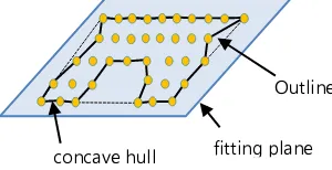
Boundary point detection is the most important work in this study. The idea is to find the points that above the building rooftop first, which is called roof points. This can be done by estimating the height of the rooftop of a building. Figure 6 shows the concept. By projecting the roof points onto the horizontal plane, we can find boundary points by using a concave-hull algorithm. Therefore, the process of boundary point detection can be divided into two steps: estimation of the height of rooftop and calculation of concave-hull.
Figure 6. The concept of selecting laser points above the height of rooftop.
Based on the segmented coplanar points, one can calculate the projected area of the convex hull of each point cluster. We assume that the covering area of a roof part would be larger than a certain amount. A procedure to estimate the height of rooftop is developed by this principle.
2.3.2 Calculation of concave hull
To find boundary points of a building, we can trace the outlines of extracted rooftop point clusters by using a modified convex-hull algorithm (Andrew, 1979; Sampath and Shan, 2007), which is also called concave-hull algorithm. The area of a concave hull is smaller than the area of convex hull as shown in Figure 7. To obtain a proper concave hull, a length constraint of polygon edges is introduced. If the distance between two adjacent points longer than the length constraint, this line segment will be dropped and next neighbor points which fulfill the length condition will be considered.
We can trace the boundary of the cluster of all points above rooftop as well as the boundaries of segmented clusters, so that
not only the building outline can be extract but also the structure lines of the building. Figure 8 shows an example of extracted building outline and structure lines, in which (a) is the image of segmented point clusters of the roof points and (b) is the resulted boundary lines.
Figure 8. An example of extracted building outline and structure lines: (a) the image of segmented point clusters of the roof points; (b) the results of extracted boundary lines.
2.4 Extraction of building boundary lines
For most cases, building boundary lines can be formed by the extracted boundary points. However, they will not be good enough to represent the building boundaries, when a building has parapets on the roof. To solve this problem, points on top of the parapets should be included as boundary points as well. Referring the description of figure 10, the first and intermediate echo points of multiple returns are potential parapet and boundary points, which should be included for the extraction of building boundary lines.
It is assumed that most building boundary shapes can be formed with straight line segments, so that the algorithm is designed to find fitted line segments with the detected building boundary points. There are 3 steps in the procedure. First, the data points are projected onto the horizontal plane for the detection of straight lines by using Hough transform. Second, a line fitting process is applied to find 3D lines. Third, line segments are detected by checking the point distribution along the 3D straight lines.
� = �%���� + �%����, � = [0, �] (1)
Figure 9. An example of extracted 2D lines by using Hough transform.
The collinear points in the horizontal plane are not necessary collinear in 3D space. To find the collinear points in 3D space, a line fitting process is applied. The best-fitting line of points can be computed by least squares adjustment if these points are continuously collinear as shown in Figure 10. The group of points that have the distances apart from the fitting line smaller than a threshold are extracted to calculate parameters of the best-fitting line. The final step is finding line segments along those collinear points by detecting the two end points of each line segment.
Figure 10. The conceptual illustration of the proposed line fitting process.
3. EXPERIMENTS 3.1 Test site and data
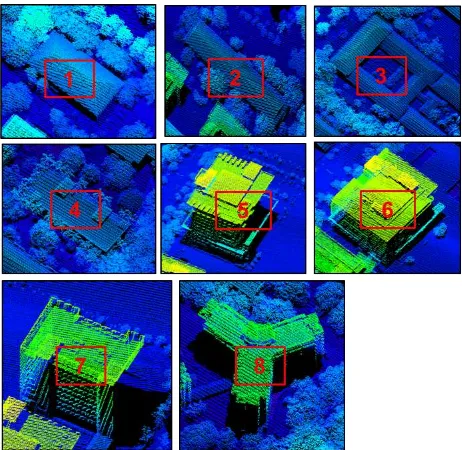
The test site locates in National Cheng Kung University campus. From the test area, 8 campus buildings of various types were selected as test objects, which are numbered from 1 to 8. Figure 11 shows the aerial image of test area and the selected test objects. Three of the test objects are gable-roof buildings, and the other five are flat-roof buildings. Some of them have simple shapes, but some of them include many complex structures. Some of the flat-roof buildings have parapets on the roofs, and some low buildings are partially covered by trees. The test results of those test objects would be able to demonstrate the feasibility of the proposed method.
The airborne LiDAR data of the test area were acquired with the Optech ALTM30/70 airborne LiDAR system. The flight high was about 500 m, and the point density is about 8.7 pt/m2. Figure 12 shows all of the point cloud datasets with respect to the number sequence of the test objects.
Figure 11. The aerial image of test area and the selected test objects.
Figure 12. All of the point cloud datasets with respect to the sequence of the test objects.
3.2 Results and discussions
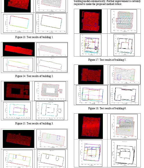
Each dataset was processed through the four major steps of point cloud classification, segmentation, boundary point detection and boundary extraction. For each test object, the intermediate and final results of the processing steps are shown sequentially in Figure 13 to 20. In each figure, the image in the upper-left corner shows the extracted building points, which are resulted from the process of point cloud classification. The picture in the upper-right corner shows the segmented coplanar points and detected boundary points, which are resulted from the procedure of segmentation and boundary point detection. The picture in the lower-left corner shows the extracted 2D straight lines from the boundary points after Hough transform. The picture of the lower-right corner shows the final results of the extracted building boundary lines.
First of all, we can look at the test results of building 1 to 4, which are low buildings with simple shapes. Most of the boundary lines of these buildings were correctly extracted, even for the buildings partially covered by trees. Although some rugged edges of roof boundaries were not followed very well, those extracted building boundary lines should be good enough to form the building outlines. We did not extract the structure lines for those gable-roof buildings in this study. If they are needed to construct building models, one can obtain the structure lines by interesting extracted neighboring plane features (Wang
Collinear points Fitting line
and Tseng, 2010). The boundary lines were extracted well too for the two higher structures on the roof of building 4. Those boundary lines would also be important for the reconstruction of building models. Based on this observation, we can conclude that building boundary lines can be extracted effectively for most simple shape buildings.
Figure 13. Test results of building 1.
Figure 14. Test results of building 2.
Figure 15. Test results of building 3.
Figure 16. Test results of building 4.
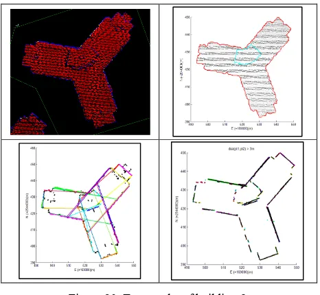
Secondly, we can check the test results of building 5 to 8, which are tall buildings with complicated shapes. These buildings also have parapets and other structures on their roofs. Although most building boundary lines were extracted, building outlines seem to incomplete due to some missing lines. We can see some double edges of building boundary too. They were mainly caused by the effects of parapets or ancillary facilities on the roofs. The extracted building boundary lines may be helpful to reconstruct building models, but they are not sufficient to form building models automatically. Further improvement is certainly required to make the proposed method robust.
Figure 17. Test results of building 5.
Figure 18. Test results of building 6.
Figure 20. Test results of building 8.
The extracted building boundary lines can be divided into two categories. Lines can be used to form building outlines belong to the first category. The second category includes the edge lines of building ancillary structures. Boundary lines of the first category are elements to form building outlines, which are substantial features to represent buildings in traditional topographic maps. On the other hand, lines of the second category are the key features for reconstructing 3D building models. We believe that they are valuable 3D geometric information can be retrieved from airborne LiDAR data.
4. CONCLUSION
The proposed method is feasible to extract building boundary lines from airborne LiDAR data. The extracted line features are essential elements to form building outlines and can be useful to reconstruct 3D building models. The proposed method can handle buildings with simple shapes very well, and can deal with complicate buildings with parapets and ancillary structures on the roofs to obtain reasonable boundary lines. Although most building boundary lines were extracted, building outlines seem to incomplete due to some missing lines. We can see some double edges of building boundary too. Further improvement is certainly required to make the proposed method robust.
The use of first and intermediate laser returns can significantly improve the detection of building outlines. However, misdetection and double edges cannot be avoided due to some complicated roof structures. Insufficient point density of the could be one of the reasons of getting bad results. Some bad results can be fixed by changing some threshold settings of parameters applied in the procedure. However, it would be difficult for a user to set proper thresholds with respect to various building types.
ACKNOWLEDGMENT
This research has been supported by National Science Council (NSC) under project number: NSC101-2221-E-006-181-MY3.
REFERENCES
Al-Durgham, M., E. Kwak and A. Habib, 2012. Automatic Extraction of Building Outlines from LiDAR Using the Minimum Bounding Rectangle Algorithm, Proceedings of Global Geospatial Conference.
Andraw, A.M., 1979. Another efficient algorithm for convex hulls in two dimensions, Information Processing Letters, 5(9), pp. 216-219.
Dorninger, P. and N. Pfeifer, 2008. A comprehensive automated 3D approach for building extraction, reconstruction, and regularization from airborne laser scanning point clouds,
Sensors, 8(11), pp. 7323-7343.
Hough, P.V.C., 1962. Method and means for recognizing complex patterns, United States: U.S. Atomic Energy Commission.
Jarzabek-Rychard, M., 2012. Reconstruction of building outlines in dense urban areas based on LiDAR data and address points, International Archives of Photogrammetry, Remote Sensing and Spatial Information Sciences, XXXIX(B3), pp. 121-126.
Kada, M. and A. Wichmann, 2012. Sub-surface growing and boundary generalization for 3d building reconstruction, ISPRS Annals of the Photogrammetry, Remote Sensing and Spatial Information Sciences, Vol. I-3, pp. 233-238.
Kim, C. and A. Habib, 2009. Object-Based Integration of Photogrammetric and LiDAR Data for Automated Generation of Complex Polyhedral Building Models, Sensors, 9(7), pp. 5679-5701.
Ma, R., 2005. DEM generation and building detection from LiDAR data, Photogrammetric Engineering & Remote Sensing, 7(71), pp. 847-854.
Sampath, A. and J. Shan, 2007. Building boundary tracing and regularization from airborne LiDAR point clouds,
Photogrammetric Engineering & Remote Sensing, 7(73), pp. 805-812.
Tseng, Y.H. and S. Wang, 2003. Semi-automated Building Extraction Based on CSG Model-Image Fitting,
Photogrammetric Engineering & Remote Sensing, 2(69), pp. 171-180.
Vosselman, G. and S. Dijkman, 2001. 3D building model reconstruction from point clouds and ground plans, International Archives of Photogrammetry and Remote Sensing, 34(3/W4), pp. 37-43.
Wang, M. and Y.H. Tseng, 2010. Automatic Segmentation of Lidar Data into Coplanar Point Clusters Using an Octree-Based
Split-and-Merge Algorithm, Photogrammetric Engineering &
Remote Sensing, 76(4), pp. 407-420.
Wang, M. and Y.H. Tseng, 2011. Incremental Segmentation of LiDAR Point Clouds with an Octree Structured Voxel Space,
Photogrammetric Record, 26(133), pp. 32-57.