BUILDING FACADE OBJECT DETECTION FROM TERRESTRIAL THERMAL
INFRARED IMAGE SEQUENCES COMBINING DIFFERENT VIEWS
L. Hoegner∗, U. Stilla
Photogrammetry and Remote Sensing, Technische Universitaet Muenchen - (ludwig.hoegner, stilla)@tum.de
KEY WORDS:Urban, Combination, Terrestrial, Infrared, Sequences, Extraction, Texture, Building
ABSTRACT:
This paper discusses the automatic texturing of building facades from thermal infrared image sequences. A fully automatic method is presented to refine GPS based positions estimating relative orientations of the image sequences including a given building model in a bundle adjustment process. The resulting refined orientation parameters are used to extract partial facade textures from all images and all sequences. The resulting partial textures of every sequence are combined to get complete facade textures in the thermal infrared domain. Textures from different image sequences are combined for object detection and extraction. These sequences are acquired either at different times for different radiometric thermal behavior of facade objects or with different viewing directions for objects located before or behind the facade plane.
1. INTRODUCTION 1.1 Motivation
Today, IR inspections of buildings are still done in the image domain by analysing single images with image processing tech-niques (Balaras and Argiriou, 2002). The images are mainly taken manually for a single building only. However, mobile map-ping systems are more and more used to carry out large area in-spections for urban quarters or entire cities. The IR cameras can be mounted on a mobile terrestrial or a flying platform. Terrestrial images (Hoegner et al., 2007) taken from a vehicle can be used for documentation of frontal faces visible from the street level, while airborne images taken from an unmanned aerial vehicle (UAV) or helicopter can capture roofs. Using oblique view images inner yards can also be covered (Iwaszczuk et al., 2012). In contrast to images in the visible spectrum, textures in the thermal infrared spectrum can be used to extract objects under the surface like heating pipes and thermal leakages. First attempts for window ex-traction using grammars have already shown the potential of ther-mal infrared textures (Michaelsen et al., 2012). Combining IR images with 3D building information requires spatially referenc-ing the data. Image data from different points in time, different platforms and multiple images (video sequences) can be fused. The assignment of the images to the 3D building model should be done automatically and can be achieved via texture mapping. As thermal infared cameras are from their construction limited to image dimensions between 320x240 and 1024x768 pixel, a small field of view is chosen to increase the geometric resolution of the textures on the facades. Due to this, single images show only small parts of facades. The complete facade is recorded within the sequence.
1.2 State of the Art
Today, automatic 3d reconstruction and texture extraction is fo-cused on high resolution images and image sequences from the visual spectrum. These methods are mainly using homologous points to link the images in a relative orientation and extract 3d coordinates for the homologous points (Hartley and Zisserman, 2004). Some of these methods also include a self-calibration for
∗Corresponding author
the camera (Agarwal et al., 2009; Longuet-Higgins, 1981; May-bank, 1993; Mayer et al., 2012). The resulting camera orienta-tions and 3d points have to be transferred from the model coordi-nate system to the global coordicoordi-nate system either using external GPS/INS orientation information and / or a matching with given 3d building models.
If a 3d building model is already given in the beginning, a match-ing of the images and the buildmatch-ing model can be done (Haral-ick et al., 1989, 1994; Horaud et al., 1989; Quan and Lan, 1999; Triggs, 1999; Zhi and Tang, 2002). This matching can be based on line segments, control points, or surfaces. The limitation of these methods is the accuracy and level od detail of the building model with respect to the scene visible in single images. If in an image there are only few parts of line segments, a correct match-ing of the image and the 3d model is often not possible. If small facade objects should be extracted, a small field of view should be chosen as mention in subsection 1.1. As most existing build-ing models do not have detailed geometry beyong facade planes, a direct matching of single images and 3d building models is not possible.
Especially for thermal infrared images with their low image size, the number of feature points that can be used as homologous points is low compared to images in the visible spectrum. To find a good set of homologous points and remove outliers, the RANSAC algorithm (Fischler and Bolles, 1981) is used in most solutions, where random minimal sets of homologous points are used to estimate a relative orientation, that is checked against the other homologous points. A reduction to a minimum set of five corresponding points is possible for known interior orientation (Nister, 2004). This reduces the possibility of outliers in the mini-mum set of the RANSAC and increases the quality of the best rel-ative orientation. An additional quality improvement is the exten-sion of image pairs to image triplets (Hartley, 1997; Fitzgibbon and Zisserman, 1998; McGlone, 2004; Stewenius et al., 2005). Espacially for image sequences with a constant viewing direction, the trifocal tensor derived from image triplets increased signifi-cantly the stability of the relative orientation compared to image pairs using the fundamental matrix.
re-sulting 3d points allow the extraction of windows (Reznik and Mayer, 2008). Introducing a semi-global matching (Hirschmller, 2008) dense point clouds can be generated from the relative ori-ented image sets (Mayer et al., 2012). This method is also applied to image sets from UAVs (Bartelsen and Mayer, 2010).
Combining the Five-point-algorithm (Nister, 2004) with plane sweeping (Yang and Pollefeys, 2003) a rough model of the scenery is calculated in close real time (Pollefeys et al., 2008). Necessary camera orientations are calculated using the relative movement of homologous points through the image sequence(Nister et al., 2006) and a Kalman filter using additional GPS/INS data (Grewal and Andrews, 2008).
Recording image sequences of building facades most of the ho-mologous points are on the facade plane. This has a significant influence on the quality of the relative orientation as the recon-struction of the interior orientation is not possible from a pla-nar scene (Maybank, 1993). For calibrated cameras with known interior orientation a planar scene has two solutions in general (Longuet-Higgins, 1986; Maybank, 1993). The geometrical cor-rect solution can be found by searching the solution with all 3d points in front of both cameras. For planar scenes the homogra-phy is an alternative way of orienting image pairs (Hartley and Zisserman, 2004; Pollefeys et al., 2002).
There is quite a limited number of works on transferring meth-ods for geometric calibration and 3d reconstruction to the ther-mal infrared domain. A geometric calibration including principal point, focal length, and radial distortion parameters has been in-vestigated by some groups (Simmler, 2009; Luhmann et al., 2010; Lagela et al., 2011). 3d reconstruction and texture extraction in thermal infrared are applied for sets of images (Gehrke et al., 2013) and ordered image sequences (Hoegner et al., 2007). Both 3d reconstruction and texturing are influenced by various condi-tions as the thermal radiation of facades depends on temperature differences between inside and outside, weather conditions, and materials. To overcome limitations in the 3d accuracy of ther-mal infrared based 3d points, a combination of therther-mal infrared cameras and 3d recording systems like laserscanners (Borrmann et al., 2013) and time-of-flight cameras (Hoegner et al., 2014) is possible.
2. METHODOLOGY
The proposed concept is based on the assumption that a 3d model of the recorded building is given containing 3d vertex coordinates and triangulated polygon surfaces with given texture coordinates. The 3d coordinates of the building are given in UTM. Instead of generating an isolated only relative oriented model, in this ap-proach the image sequence is matched with the pre-known build-ing model and measured camera path. Several matchbuild-ing steps are performed:
At first, a camera orientation is interpolated for every image of the sequence from the recorded GPS/INS data. Starting with the first image pair, homologies points are tracked through the images. Given the camera orientation and known camera calibration, the observed image coordinates are used to calculate 3d coordinates in a bundle adjustment. Estimated 3d points of a facade should be on or close to a polygon face of the given 3d model. This con-straint is added in the adjustment to minimize the distance of the extracted 3d points to the polygon surface and remove outliers.
After this step, the corrected camera orientation is used to project the polygonal model into the images of the sequence to interpo-late intensity values for the facade textures. To be able to com-bine several images of a facade for the final facade texture, the resolution of the outgoing texture is defined first. Caused by the strict order of the sequence partial occlusion of facades have to be taken into account. This procedure is repeated for every visi-ble facade in every input image of the sequence. Additionally, for every pixel of the texture, the geometric resolution is stored.
The resulting complete texture is calculated by merging the pixel values of the partial textures. This is achieved by copying one over another in the order of the time stamps. Using an oblique view for the recorded sequence, every visible pixel of a texture has a higher geometric resolution than the texture before. To overcome remaining positioning errors, a line matching between the partial textures is included in this step.
The combination of textures from different times and viewing di-rections is then done based on the texture coordinates of the fa-cades.
2.1 Orientation of image sequences
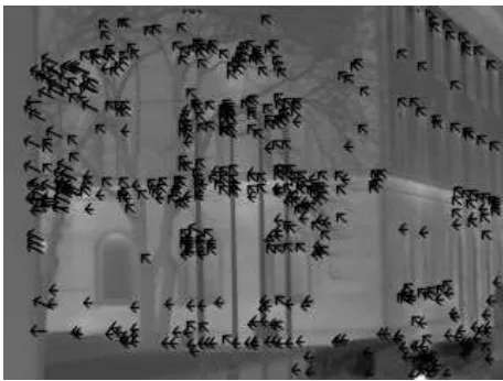
Given the known interior orientation of the thermal infrared cam-era from an initial geometric calibration (Simmler, 2009; Luh-mann et al., 2010), SIFT features (Lowe, 2004) are tracked through the images of a sequence using cross-correlation. Figure 1 shows an example of features tracked in the sequence where the arrows point in the direction of the movement of the features between two images.
Figure 1. IR image with selected SIFT features, that have cor-respondences in the following image. Arrows show the moving direction of the points
Using the collinearity equations as basis in the bundle adjustment the observations are given as the image coordinates (xik, yik) whereiis the numbering of homologous image points of an ob-ject point(Xi, Yi, Zi)andk ∈ [1, n]the numbering of the im-ages(B1...Bn)of the sequence. The object point coordinates are unknowns where an initial estimation is made from two images with the longest baseline. The interior orientation(x0, y0, cx, cy) including radial distortion coefficients(A1, A2)and the exterior orientations(X0k, Y0k, Z0k, ωk, φk, κk)of the images(B1...Bn) are also unknowns with the calibration values and GPS/INS path as initial estimations.
the facade. If the facade plane is defined in Hesse normal form.
~
r·~n−d= 0 (1)
then~nis the normalized normal vector of the plane anddthe dis-tance of the plane to the origin of the coordinate system. A 3d object point P is on this plane, if its vector~r= (Xi, Yi, Zi)T
ful-fills equation 1. This equation is now used as virtual observation for every facade plane.
The assignment of a 3d object point to a facade plane is done calculating the intersection of the projection rays of the homol-ogous image points (xik, yik) through the perspective centers (X0k, Y0k, Z0k, ωk, φk, κk) and the facade planes. This inter-section is calculated using
g:~r=r~0+λ·~u, (2)
wherer~0is the position vector and~uthe direction. The position vector is the perspective centerr~0 = (X0, Y0, Z0)T. The direc-tion is the normalized vector between(x, y)and the perspective center. All points~rwithλfulfilling the equation are on the pro-jection ray. Combining equation 1 and 2 leads to
λ=d−r~0·~n
~u·~n . (3)
The resultingλinserted in the projection equation results in the intersection points(Xik, Yik, Zik)of the projection ray and the facade plane. A 3d point on a facade is an inlier, if it is a homol-ogous point in at least to images where the intersections of the projection rays with the plane are close together. Homologous points where the intersection points are not within a defined vari-ance are marked as outliers and removed from the observations. All observations are image coordinates of homologous points and thus taken as uncorrelated and with the same standard deviation for the stochastic model.
2.2 Texture Extraction
Given the refined image orientations of subsection 2.1, the poly-gons of the 3d building model are projected into the images. For the facade textures a unified geometric resolution is defined. Given the texture coordinates of the four corners of a facade
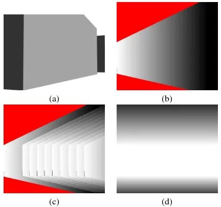
Plo= (0,0), Plu= (m−1,0), Pru= (m−1, n−1), Pro= (0, n−1)and there corresponding object coordinates(Xp, Yp, Zp) the four corner points of the texture are projected into the recorded image using the collinearity equations. This results in four point correspondences between the texture image in texture coordinates and the recorded image in image coordinates. These four corre-spondences are used to calculate the four parameters of a rec-tification. The resulting parameters are then used to calculated image coordinates in the recorded image for every pixel of the texture and interpolated its intensity value using bilinear inter-polation. Texture pixels without four neighboring pixels in the recorded image are left blank. Figure 2a shows an input image of the 3d building model projected into the image space using the re-sulting parameters of the interior and exterior camera orientation from the orientation step. Due to oblique view, the geometric res-olution decreases from the left to the right when the percentage of the facade in height is increasing (Fig. 2b). White areas have the highest geometric resolution, black areas the lowest. Non vis-ible parts of the facade are marked in red. combination of several textures of the same facade extracted from several images shows the whole facade with a geometric resolution decreasing towards the roof (Fig. 2c+d).
From figure 2c it is obvious that if textures are generated in the order of the recording sequence, an extracted partial texture has a
(a) (b)
(c) (d)
Figure 2. Geometric resolution of textures a) Oblique forward view of a facade b) Schematic view of the geometric resolution of a partial texture taken from an image in oblique forward look-ing view. white: high resolution, black: low resolution, red: not visible in the image c) resolution of a facade texture for a set of partial textures d) resolution for a facade texture from partial tex-tures of an image sequence
higher geometric resolution for all visible parts than the textures before in the same sequence. Thus, textures are simple copied one over another in recording order for all pixels with an interpo-lated intensity value. For remaining projection errors a correction is applied by matching the partial texture to add to the existing texture using corresponding feature points.
This texture extraction scheme is valid for all visible facades even those perpendicular to the viewing direction. For backward view-ing recordview-ings, the order of the texture combination has to be flipped because now the geometric resolution decreases within the sequence as the camera is moving away from visible points.
2.3 Combined analysis of textures from different views As mentioned in subsection 2.2, all facade textures are calculated with the same geometric resolution. So all textures of one facade from different image sequences have the same dimensions. Dif-ferent texture are extracted for forward and backward view and for different times comparing evening and morning textures. The different textures are combined using an intensity vector with the intensities of the different textures for every texture pixel coordi-nate.
The combination of textures from different recording times but almost same viewing direction is used to analyze dynamic pro-cesses as different parts of facades show - depending on their materials - different cooling and warming behavior. As the radia-tion of surfaces may depend on the viewing direcradia-tion, the almost same viewing direction is chosen for this texture combination.
P1 P2
B1 B2
(a) (b)
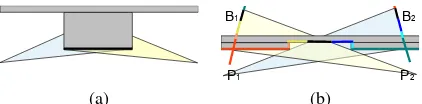
Figure 3. Occlusions caused by oblique view: a) Forward and backward recording geometry of a flat facade. b) Forward and backward recording geometry of a window. Caused by the oblique views both images show different parts of the window and the inner part is shifted in both images B1 and B2
The general setup of the texture generation allows the combina-tion of textures extracted from different sensors in the visible, near infrared, midwave thermal infrared and longwave thermal infrared. The combined analysis of textures from these spectral bands is still ongoing.
The combined analysis of textures from different views is used for leakage detection. In thermal infrared images, leakages ap-pear as areas with higher emission values than the surrounding surface. Other facade elements show a similar radiometric be-havior. Ledges are exposed objects on a facade an thus loose more energy than the facade plane. Reveals store at their up-per ledge warm rising air. Both effects look similar to leakages. And different material can cause different intensities for the same temperature. It is assumed that material changes on a facade ei-ther concentrate on small areas and belong to facade objects or divide the facade into a few big, extensive areas. If objects be-fore and behind the facade plane are masked out by identifying pixels with disparities in the two textures, the remaining facade textures contains the homogenous facade plane. Small segments in this remaining textures with a significant intensity difference to the local neighborhood of the facade are then candidates for leakages.
A histogram of the remaining texture pixels is used to find the
max(p(g))for all intensitiesg. Under the assumption, that the majority of the texture pixels shows facade plane without leakage, this maximum is the mean temperature of the facade plane with-out leakages and objects. It is further assumed that the intensities of possible leakages are further local maxima in the histogram. A region growing is used to group pixels with similar intensity val-ues. Adjacent regions with similar intensities are merged. In the end, there remains a big region of the facade plane and leakages as small segments.
3. EXPERIMENTS
Our experiments have been taken using a SC3000 thermal in-frared camera with a detector of 320x240 pixels and a tempera-ture resolution of 0.02 K. Image sequences have been taken after sunset and before sunrise. Figure 4 shows some images out of four sequences in forward view showing different facades of a building complex. One sequence shows a group of facades with different orientation and occlusions (Fig. 4a). The other scenes show several building parts in the same plane but with differ-ent structures (Fig. 4b-d). The sequence was recording with 50 frames per second. This allows a very good feature tracking due to only small movements between the images. For the 3d recon-struction every 10th image was taken to reduce the computational effort and guarantee a 3d base necessary for the initial 3d point estimation.
3.1 Texture extraction
The estimated 3d point coordinates and camera orientations af-ter the bundle adjustment are mainly depending on the number
(a) (b)
(c) (d)
Figure 4. Overview over recorded scenarios with the SC3000 thermal infrared camera looking forward a) Several facades with different orientation and occlusions. b) Three building parts in the same facade plane but with different structure, the modern one with a repetitive pattern in the windows. c) Several small building parts in the same facade plane d) Several building parts of different type in the same facade plane. Bridges occluding parts of the facades.
and quality of the feature points that are tracked through the se-quences. In table 1 the detected SIFT features in thermal image sequences are compared to a video sequence recorded at the same time in original resolution (768×576) and down sampled to the same resolution as the thermal images (320×280).
SIFT
Video 768 Video 320 IR 320
# Interest points 1246.2 531.4 168.4
1 frame per second
# homologous points 287.2 124.7 31.9
tracking time in seconds 11.6 11.6 10.4 sum of squared differences 0.006 0.011 0.025 5 frames per second
# homologous points 683.3 244.6 129.2
tracking time in seconds 11.8 11.8 10.5 sum of squared differences 0.005 0.009 0.012
Table 1. Quality of Feature points. Mean values over all se-quences. Number of features in images in the visual spectrum (original resolution and down sampled) compared to number of features in thermal infrared.
Due to the lower contrasts and lack of small details the number of detected features is much lower in the thermal images than in the visible spectrum. Nevertheless a sufficient number of features is tracked through the sequence. The differences in the tracking time result from the oblique view and the lower contrast in the thermal scene as features are detected first not directly when they first appear in the image but only after several images of the se-quence when their size allows a detection. The sum of squared differences (SSD) indicates how similar two homologous points are in different images. A SSD of 0 means they are totally equal.
An exemplary 3d point cloud and camera path can be seen in fig-ure 5 . The 3d points are grouped along the window rows where the thermal images show the highest gradients. In the center the tree is extracted. Its points are not used for the orientation im-provement as they are to far away from a 3d model surface but are calculated in the bundle adjustment.
Figure 5. 3d point cloud and estimated camera path.
without pre-knowledge at 5 frames per second, only the feature points and interior orientation are used as observations where the object coordinates and exterior orientations of the cameras are the unknowns. The resulting standard deviations for the unkowns are listed in table 2.
Comparing these standard deviation to the standard deviations for the unknowns including pre-knowledge of the building model (ta-ble 3) show small improvements on the accuracy of the bundle adjustment.
relative orientation 4a 4b 4c 4d
σxy[µm] 0.3857 12.74 0.9486 14.71
σXY Z[m] 0.06855 0.3627 0.1068 0.3815
σX0[m] 0.1285 0.2512 0.08374 0.3486
σY0[m] 0.04055 0.1856 0.2731 0.4502
σZ0[m] 0.02063 0.05744 0.06718 0.0815
σω0[gon] 0.03016 0.05230 0.6114 1.029
σφ0[gon] 0.06945 0.2041 0.09485 0.5176
σκ0[gon] 0.2259 0.4583 0.5834 1.923
Table 2. Accuracy of the relative orientation without pre-knowledge
absolute orientation 4a 4b 4c 4d
σxy[µm] 0.3534 1.529 0.9185 1.405
σXY Z[m] 0.05944 0.1910 0.09583 0.1748
σX0[m] 0.04454 0.06776 0.04969 0.03390
σY0[m] 0.02294 0.01750 0.1005 0.1972
σZ0[m] 0.009547 0.03065 0.06421 0.04909
σω0[gon] 0.02323 0.3148 0.5981 0.6936
σφ0[gon] 0.02196 0.08770 0.05319 0.4930
σκ0[gon] 0.2016 0.3806 0.5991 1.522
Table 3. Accuracy of absolute orientation including pre-knowledge of the building model
Whereas the improvements for 4a and 4c are quite small, the im-porvements for 4b and 4d are significant. 4b and 4d have very high standard deviations in the relative orientation compared to 4a and 4c. This is caused by the homogenous structure of the facades (4b) and the occlusions (4d). Both scenarios show less homogeneous points that can be tracked through the sequence and more false correspondences.
Including the building model allows to remove more false cor-respondences which helps in sequence 4d. In sequence 4b the known facade plane assists in estimating the movement of the features through the sequences.
Despite the standard deviation, the accuracy of the oriented se-quence to the building model is necessary for an accurate tex-ture extraction. Whereas in the bundle adjustment including the building model the sequence is already matched to the building
model, in the relative orientation without pre-knowledge, the se-quence and the extracted 3d object points have to be matched to the building model, a step, that introduces additional deviations of0.05meters in X,Y, and Z and0.02gon inω,φ,κ.
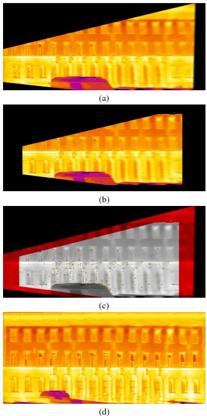
Figure 6 shows one example texture extracted after orientation with pre-knowledge. As the partial textures (fig. 6a+b) are ex-tracted from an oblique view, the spatial resolution is not con-stant. It is getting lower from the left to the right. Due to this the textures are blurred at the right. On the other hand, on the left side only the first and parts of the second floor are visible. The third floor is visible only in the low resolution right part. A correlation is done for every added texture to remove remaining positioning errors (fig. 6c). Combining several of these partial textures leads to the complete texture given in figure 6d. The total facade is vis-ible in the texture but with different geometric resolutions. For the first and second floor the resolution is higher than for the third floor. The big bus standing in front of the building could only be removed to a small part because it was occluding the facade in all images.
(a)
(b)
(c)
(d)
Figure 7. 3d building model with facade textures
3.2 Texture analysis
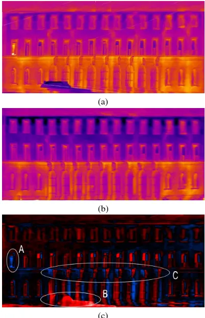
A combination of textures from forward and backward viewing images is possible, if the time difference between both recordings is small. In the experiments this is done by driving along the fa-cades first in forward view followed by the backward view (fig. 8a+b). The resulting textures are co-registered to compensate re-maining errors in the texture projection process. In an algebraic transformation the difference of both textures is calculated pixel per pixel (fig. 8c). The left window in the middle row (fig. 8c, A) shows a higher temperature in the forward view. This win-dow was open during the forward recording and closed before the backward recording. A car is standing in front of the build-ing. Due to the oblique view, this car occludes a part of the facade in the forward view but not in the backward view (fig. 8c, B). For the windows and stone elements (fig. 8c, C) it can be seen that they show both a red and a blue border. This happens because windows and stone elements are not in the facade plane and thus are projected at a wrong position in the texture which leads to a disparity between the texture from the forward view and the texture from the backward view. Additionally both types show another intensity than the facade plane.
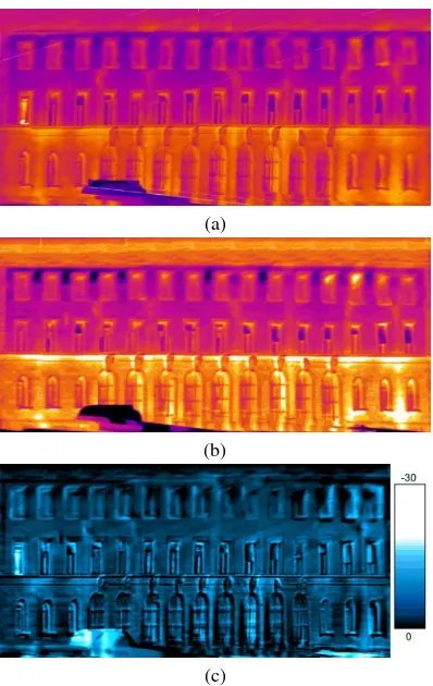
In contrast to the combination of textures from forward and back-ward viewing images a combination of textures from image se-quences recorded in the evening and in the morning (Fig. 9a+b) allows the observation of dynamic processes over time. Differ-ence texture of the coregistered textures from the evening and the morning shows the cooling of the facade over night (Fig. 9c). The color bar indicates the temperature difference in degree Cel-sius. The transfer from intensity values to temperatures is done using the radiometric calibration of the cameras and an emissiv-ity value of 95%. The biggest cooling effects can be seen again at the window that was open during the first sequence record and closed during the second record and at the car in front.
Leakages on facades are defined as regions with a higher intensity than the facade plane in the thermal infrared. This description is also true for other facade elements like windows. To detect the leakages, in a first step, other elements have to be masked out. As shown in figure 8 elements that are not in the facade plane cause a disparity in the difference texture of the texture from forward and backward view. A segmentation is used to generate a binary mask to detect these parts of the texture (Fig. 10a). Using a region growing and morphological operators on the segments masked in the previous steps, the resulting segments are used to masked out these parts of the image (Fig. 10b).
Figure 10c shows the result of the leakage detection. In the re-maining part of the texture that has not been masked out a his-togram based threshold is used to distinguish the facade (global maximum in the histogram) and the leakages. Windows and other
(a)
(b)
(c)
Figure 8. Combination of texture from forward and backward viewing images. a) texture from forward viewing images. b) texture from backward viewing images. c) Difference image after texture co-registration. Black: constant intensity in both images. Red: higher intensity in backward viewing texture. Blue: higher intensity in forward viewing texture. A) Windows that was close after the forward viewing image recording. B) Car in front of the facade that is projected incorrect into both textures. C) Stone elements standing in front of the facade plane.
3d structures are ignored for the leakage detection. Six out of seven heating pipes in the first floor have been found correctly. In the ground floor four heating pipes are detected. The heating pipes between the big windows in the middle are missing because they are to close to the windows and masked out. Additionally, a few small leakages close to windows have been detected.
4. DISCUSSION AND OUTLOOK
Different aspects influence the quality of the extracted textures. The accuracy of the 3d reconstruction is limited compared to im-age sequences in the visual spectrum. One aspect is the lower image resolution that causes a higher discretization of the scene and reduces the number of details that can be matched within the sequence. On the other hand the radiometric behavior of object in the thermal infrared leads to blurred edges and a low number of intensity changes and details. Homologous points are rarer than in the visual spectrum and worse locatable. A second aspect is the geometric calibration of the cameras. Because of the two limita-tions already mentioned, the calibration accuracy is also limited compared to cameras in the visual spectrum.
(a)
(b)
(c)
Figure 9. Cooling process in a difference texture from texture from a) evening and b) morning. c) Difference texture showing the cooling over night. Color scale in degree Celsius. Highest cooling at the open window and the car.
weightings in the iterative process. The quality of the building model itself is also a limiting factor. Building in level-of-detail 1 are only block models. In these models, the overhang at the roofs is not modeled. This causes two possible errors. If no over-hang is modeled, the facades can either be set to the position of the footprint. Then, the position of the facades is correct, but the overhang is projected onto the facade. This causes misalignment of the objects on the facade like windows and heating pipes. If the building model is generated from aerial images, the roofs outline is taken as footprint and the position of the facades is incorrect in the model. In this case, the bundle adjustment tries to move the camera path which very often works but not necessarily. The number of visible elements in the thermal infrared influences the quality of the position refinement. On facades with only few ob-jects or only repetitive patterns, the quality of the refinement is significantly reduced. If this falls together with bad initial GPS positions, the method can totally fail. The texture extraction is quite sensitive to errors in the viewing direction estimation. The combination of relative orientation and 3d model knowledge re-duces these errors significantly. Remaining errors between to par-tial textures.
Further steps in the processing of the textures are windows ex-traction, leakage detection and parameter estimation for facades. The given method can be used to record the building facades in whole streets to get first view on the quality of the thermal be-havior of the buildings. Searching objects like windows, heating pipes, or leakages in building textures instead of images allows a 3d geo-referencing and observation of thermal relevant objects i.e. in a building information model. The evaluation of time series and changes i.e. before and after a thermal optimization, summer vs. winter, evening vs. morning are possible in an automatic way.
(a)
(b)
(c)
Figure 10. Leakage detection a) Disparity from difference tex-ture of textex-tures from forward and backward view. b) Mask after post processing with region growing and morphological opera-tors. All windows are masked out. c) Marked leakages (yellow) overlayed the original texture. Windows and other 3d objects are not detected as leakages. Most of the heating pipes are detected as leakages.
ACKNOWLEDGEMENTS
The authors thank Dr. Clement, Dr. Schwarz and Mr. Kremer of Fraunhofer IOSB, Ettlingen, for their assistance during the recording campaign.
References
Agarwal, S., Snavely, N., Simon, I., Seitz, S. and Szeliski, R., 2009. Building rome in a day. In:Proceedings of the Interna-tional Conference on Computer Vision.
Balaras, C. and Argiriou, A., 2002. Infrared thermography for building diagnostics.Energy and Buildings34, pp. 171–183.
Bartelsen, J. and Mayer, H., 2010. Orientation of image se-quences acquired from uavs and with gps cameras.Surveying and Land Information Science70(3), pp. 151–159.
Borrmann, D., Houshiar, H., Elseberg, J. and Nchter, A., 2013. Vom kombinieren von 3d-modellen mit farb- und temperatur-informationen. Photogrammetrie – Laserscanning – Optis-che 3D-Messtechnik. Beitrge der Oldenburger 3D-Tage 2013
pp. 246–253.
Fischler, M. and Bolles, R., 1981. Random sample consensus: A paradigm for model fit-ting with applications to image analy-sis and automated cartography. Communications of the ACM
24(6), pp. 381–395.
Gehrke, R., Trabold, D., Greiwe, A. and Abel, J., 2013. 3d-modellierung eines bauwerkes aus rgb- und thermalaufnahmen fr das facility managment.Photogrammetrie – Laserscanning – Optische 3D-Messtechnik. Beitrge der Oldenburger 3D-Tage 2013pp. 254–263.
Grewal, M. and Andrews, A., 2008. Kalman Filtering Theory and Practice. John Wiley & Sons. ISBN 0470173661.
Haralick, R., Joo, H., Lee, C., Zhuang, X., Vaidya, V. and Kim, M., 1989. Pose estimation from correspondence point data.
SMC19(6), pp. 1426–1446.
Haralick, R., Lee, C., Ottenberg, K. and Nlle, M., 1994. Review and analysis of solutions of the three point perspective pose estimation problem.International Journal of Computer Vision
13(3), pp. 331–356.
Hartley, R., 1997. Lines and points in three views and the tri-focal tensor. International Journal of Computer Vision22(2), pp. 125–140.
Hartley, R. and Zisserman, A., 2004. Multiple View Geome-try in Computer Vision. Cambridge University Presss. ISBN 0521540518.
Hirschmller, H., 2008. Stereo processing by semiglobal matching and mutual information.IEEE Transactions on Pattern Analy-sis and Machine Intelligence30(2), pp. 328–341.
Hoegner, L., Hanel, A., Weinmann, M., Jutzi, B., Hinz, S. and Stilla, U., 2014. Towards people detection from fused time-of-flight and thermal infrared images. In: Photogrammetric Computer Vision 2014 - PCV2014, Vol. XL-3, pp. 121–126.
Hoegner, L., Kumke, H., Meng, L. and Stilla, U., 2007. Auto-matic extraction of textures from infrared image sequences and database integration for 3d building models.PFG Photogram-metrie – Fernerkundung – Geoinformation2007(6), pp. 459– 468.
Horaud, R., Conio, B., Leboulleux, O. and Lacolle, B., 1989. An analytic solution for the perspective 4-point problem.
Computer Vision, Graphics and Image Processing1989(47), pp. 33–44.
Iwaszczuk, D., Hoegner, L., Schmitt, M. and Stilla, U., 2012. Line based matching of uncertain 3d building models with ir image sequences for precise texture extraction. PFG Pho-togrammetrie – Fernerkundung – Geoinformation 2012(5), pp. 511–521.
Lagela, S., Gonzlez-Jorge, H., Armesto, J. and Arias, P., 2011. Calibration and verification of thermographic cameras for ge-ometric measurements. Infrared Physics & Technology54, pp. 92–99.
Longuet-Higgins, H., 1981. A computer algorithm for recon-struction of a scene from two projections.Nature203, pp. 133– 135.
Longuet-Higgins, H., 1986. The reconstruction of a plane sur-face from two perspective projections. In:Proceedings of the Royal Society of London. Series B, Biological Sciences, Vol. 227(1249), pp. 399–410.
Lowe, D., 2004. Distinctive image features from scale-invariant keypoints. International Journal of Computer Vision60(2), pp. 91–110.
Luhmann, T., Ohm, J., Piechel, J. and Roelfs, T., 2010. Geomet-ric calibration of therographic cameras.International Archives of Photogrammetry, Remote Sensing and Spacial Information Sciences38(5), pp. 411–416.
Maybank, S., 1993. Theory of Reconstruction from Image Mo-tion. Springer Verlag. ISBN 0387555374.
Mayer, H., 2007. 3d reconstruction and visualization of ur-ban scenes from uncalibrated wide-baseline image sequences.
PFG Photogrammetrie – Fernerkundung – Geoinformation
2007(3), pp. 167–176.
Mayer, H., Bartelsen, J., Hirschmueller, H. and Kuhn, A., 2012. Dense 3d reconstruction from wide baseline image sets. In: F. Dellaert, J.-M. Frahm, M. Pollefeys, L. Leal-Taixe and B. Rosenhahn (eds), Outdoor and Large-Scale Real-World Scene Analysis. 15th International Workshop on Theoretical Foundations of Computer Vision, Dagstuhl Castle, Germany, June 26 - July 1, 2011, Vol. 7474, Springer, Berlin, pp. 285– 304.
McGlone, C., 2004. Manual of Photogrammetry. ASPRS. ISBN 1570830711.
Michaelsen, E., Iwaszczuk, D., Sirmacek, B., Hoegner, L. and Stilla, U., 2012. Gestalt grouping on faade textures from ir image sequences: Comparing different production systemse. In: International Archives of Photogrammetry, Remote Sens-ing and Spatial Information Science, Vol. 39/B3, pp. 303–308.
Nister, D., 2004. An efficient solution to the five-point relative pose problem.IEEE Transactions on Pattern Analysis and Ma-chine Intelligence26(6), pp. 756–777.
Nister, D., Naroditsky, O. and Bergen, J., 2006. Visual odome-try for ground vehicle applications. Journal of Field Robotics
23(1), pp. 3–20.
Pollefeys, M., Nister, D., Frahm, J., Akbarzadeh, A., Mordo-hai, P., Clipp, B., Engels, C., Gallup, D., Kim, S., Merrell, P., Salmi, C., Sinha, S., Talton, B., Wang, L., Yang, Q., Stewnius, H., Yang, R., Welch, G. and Towles, H., 2008. Detailed real-time urban 3d reconstruction from video. International Jour-nal of Computer Vision78(2-3), pp. 143–167.
Pollefeys, M., Verbiest, F. and Gool, L. V., 2002. Surviving dom-inant planes in uncalibrated structure and motion recovery. In:
Proceedings of the ECCV 2002. Part II, Vol. 2351, Springer, Heidelberg, pp. 837–851.
Quan, L. and Lan, L., 1999. Linear n-point camera pose determi-nation. IEEE Transactions on Pattern Analysis and Machine Intelligence21(8), pp. 774–780.
Reznik, S. and Mayer, H., 2008. Implicit shape models, self-diagnosis, and model selection for 3d facade interpretation.
PFG Photogrammetrie – Fernerkundung – Geoinformation
2008(3), pp. 187–196.
Simmler, C., 2009. Entwicklung einer Messanordnung zur ge-ometrischen Kalibrierung von Infrarot-Kameras. Bachelorar-beit der Technischen Universitt Mnchen.
Stewenius, H., Schaffalitzky, F. and Nistr, D., 2005. How hard is 3-view triangulation really? In:Proceedings of the Tenth IEEE International Conference on Computer Vision, Vol. 2005(1), pp. 686–693.
Triggs, B., 1999. Camera pose and calibration from 4 or 5 known 3d points. In:Proceedings of the Seventh IEEE International Conference on Computer Vision, Vol. 1999(1), pp. 278–284.
Yang, R. and Pollefeys, M., 2003. Multi-resolution real-time stereo on commodity graphics hardware. In:IEEE Computer Society Conference on Computer Vision and Pattern Recogni-tion, Vol. 2003, pp. 211–217.
Zhi, L. and Tang, J., 2002. A complete linear 4-point algo-rithm for camera pose determinatio. MM Research Reprints