UAV ARCHAEOLOGICAL RECONSTRUCTION: THE STUDY CASE OF CHAMARTIN
HILLFORT (AVILA, SPAIN)
A. L. Muñoz-Nieto a, P. Rodríguez-Gonzálvez a, D. González-Aguilera a, *, J. Fernández-Hernández a, J. Gómez-Lahoz a, I. Picón-Cabrera a, J. S. Herrero-Pascual, D. Hernández-López b
a
Department of Cartographic and Land Engineering; High School of Ávila,
University of Salamanca, Hornos Caleros, 50, Ávila, 05003, Spain - (almuni, daguilera, pablorgsf, j.f.h, fotod, ipicon,
sabap)@usal.es
b
Regional Development Institute-IDR, University of Castilla-La Mancha, Albacete, 02071, Spain -
[email protected]
Commission V, WG V/4
KEY WORDS: Aerial, Photogrammetry, Computer, Vision, Image, DEM/DTM, Reconstruction, Archaeology
ABSTRACT:
Photogrammetry from unmanned aerial vehicles (UAV) is a common technique for 3D modelling in a low-cost way. This technique is becoming essential to analyse the cultural heritage, e.g. historical buildings, monuments and archaeological remains in order not only to preserve them, but for disseminate accurate graphic information. The study case of Chamartin hillfort (Ávila, Spain) provided us the opportunity to apply automation techniques to generate geomatic products with high metric quality. A novel photogrammetric software tool was used with the aim to achieve high resolution orthophoto and 3D models of complex sites. This tool allows a flexible way for heritage documentation, since it incorporates robust algorithms to cope with a wide range of studies cases and shooting configurations.
* Corresponding author. This is useful to know for communication with the appropriate person in cases with more than one author. 1. INTRODUCTION
Three dimensional scenes and objects modelling constitutes a technological field which is recently involved in a constant revolution due to the confluence of computer vision and photogrammetry. The reconstruction of complex areas such as archaeological sites is nowadays possible in an accurate and effective way because of sensors development and hybridization, and the improvement of algorithm’s processing. At this point Unmanned Aerial Vehicles (UAV) offer many possibilities to obtain cartographic products in large scales, providing an outstanding documentation for the cultural heritage preservation.
UAV and the associated Geomatic technologies have significantly contributed to spread the range of photogrammetric applications in different fields such us: agriculture (Xiang and Tian, 2011), emergency operation (Haarbrink and Koers, 2006), mine mapping (Liu et al., 2012), forest inventory (Wallace et al., 2012) or power line inspection (Li et al., 2010).
Archaeological researching requires increasingly Geomatics documentation. It is a well-known fact that graphics and infographics add value not only for conservation and reconstruction purposes but for disseminating knowledge and information.
At this point one of the main photogrammetric challenges is to achieve a total automation of the image-based 3D reconstruction process. This challenge involves not only the proper resolution of the space resection, but the capability of working with different types of images, platforms, cameras and shooting configurations or calibrations. To solve these
requirements a software package was developed and applied to the study case showed in this paper.
1.1 Applicability of UAV technology in archaeological sites
UAV have been applied successfully in archaeological contexts since middle 2000’s as it is shown in Eisenbeiss et al. (2005), who employed a rotorcraft for DSM generation. This technology fit the demanded criteria required by archaeological community: accuracy and low-cost (Sauerbier et al., 2011) Photogrammetry from UAV is based on two main components. On the one hand, those related to the aerial platform and its navigation system should be considered. On the other hand, different image acquisition sensors should be taken into account.
Aerial UAV platforms have been classified according to different criteria such as weight, airspeed, purpose, etc. (Maddalon et al., 2013). To put it simply we could consider three different categories: multirotor (Rinaudo et al., 2012) (Brumana et al., 2013), mini-helicopter (Lambers et al., 2007) and fixed-wing (Chiabrando et al., 2011).
The multirotor UAV platforms have the capability of vertical taking-off and landing in small areas as well as lower flight height than the fixed wing (Zhang et al., 2013). Taking into account these advantages, they are more suitable for surveying open archaeological areas, acquiring images from multiples points of view to achieve a complete 3d model.
In spite of the fact that the widely used sensor is the RGB camera, others optical sensors working in the not visible range of the electromagnetic spectrum such as thermal camera, near infrared, or even microwave may be used to acquire aerial
images for archaeological purposes. This kind of sensors are able to obtain further information from non-visible spectrum wavelengths. Since they are becoming smaller, it is possible to board them as a UAV payload. Some examples of thermal cameras can be shown in Brumana et al., (2013) who obtained thermal orthophotos, which allow discovering rock formations partially buried. A similar approach was done by Poirier et al., (2013), to detect ancient roads, land plots boundaries, site plans and underground caves.
Besides using UAV photogrammetry for mapping archaeological sites from point clouds and orthophotos, acquired information can be used for further archaeological analysis. In that way, Esposito et al., (2013) applied feature detection methods in order to extract the relevant structures for archaeological studies; Hendrickx et al., (2011) measured the volume of burial mounds from photogrammetric DEM in order to achieve the visualization of the original state of the monument; and (Chiabrando et al., 2011) generated solid true orthophotos which allowed 3D measurements and photo-interpretations
2. AREA OF STUDY
The hillfort of Chamartin or ‘Mesa de Miranda’ (Avila County, Spain) was inhabited by vettones between late fifth and the first century BC, and is one of the largest settlements with 2832 m of wall covering an area of 30 ha (Molinero-Perez, 1933). It is located on a granitic plateau between the confluence of two streams. These streams have a seasonal nature and they were responsible of the erosion that created the cliff at north of the hillfort, making it an strategic emplacement (Baquedano and Martín, 2007)
The hillfort was studied in two different periods in five campaigns: 1932-1934, 1943, 1945 (Cabré-Aguiló et al., 1950) with recent studies regarding to a vettonian domestic architecture (Gonzalez-Tablas, 2008). The estimated population of the hillfort was 300-375 inhabitants, according to the necropolis findings of Cabré (Alvarez-Sanchis, 2001). The occupation begun in the second Iron Age (Fabian, 1986) when the settlement was reinforced by walls.
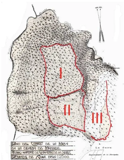
This oppidum or hillfort consist of three walled enclosures (Figure 1) built following this chronological sequence (Molinero-Perez, 1933; Gonzalez-Tablas, 2009):
First enclosure (12 ha) with 1303 m of wall perimeter, corresponds to the acropolis where were found pieces of mill stone and spindle whorls (‘fusayolas’)
South second enclosure (7 ha), constitutes the residential, production and store area (Cabre-Aguiló et al., 1950). It is connected to the acropolis through two simple gates in the wall which measures 1176 m. Chronologically, this expansion took place at the end of the fourth century BC
The building of third enclosure began at second century BC. With 1631 m of perimeter, it is partially walled in 1273 m, and it was the latest built since occupied part of the necropolis. It had three gates but without communication with the acropolis. Since the buildings had not foundation it was probably an agglomeration of houses and stables (Alvarez-Sanchis, 2005), due to the livestock was the leading economic activity of vettones (Gonzalez-Tablas, 2008)
Figure 1. Topographic map of the hillfort. The three enclosures are marked in red. From Baquedano and Martín (2007).
Regarding to the defensive scheme of the hillfort, it was composed by a large trench and chevaux-de-frise in the entrances of the residential enclosures (Alvarez-Sanchis, 2005). Moreover the walls were built around 5 m of width to protect against siege operations that, at the time, were carried out by battering ram and sapping (Molinero-Perez, 1933).
The date of its abandonment is uncertain, but it is estimated around 153 BC and not after 133 BC (Gonzalez-Tablas, 2008), and the cause could be the uselessness of defensive systems against well-organized armies (Gonzalez-Tablas, 2009). The necropolis is located south in an open area where there were discovered 2230 graves (Cabré-Aguiló et al., 1950). Six different burial areas were identified by a vertical milestone, or stele, which a variable height between 50 and 160 cm. These steles were used to establish an astronomic calendar based on Solstices and Celtic religious festivals (Baquedano and Martín, 2007).
Concerning the archaeological findings, they can be grouped into five kinds according to Molinero-Perez (1933): ‘Verracos’ or zoomorphic stone sculptures, found in the third enclosure and related to the sacred protection of livestock (Alvarez-Sanchís, 2005); Ceramics as fragments of Campania's ceramic and indigenous ones modelled by hand and decorated with stampings; Glass as pieces of glasses and necklace beads; Iron findings as fragments of swords, daggers, spears or horse bits; and Bronze ones as ring fibulae, Hispanic or ‘La Certosa’ type.
3. IMAGE-BASED MODELLING PIPELINE
Next, the workflow carried out is described. Firstly, the technical characteristics of the platform are described along with the RGB camera shipped (section 3.1). This sensor provided the input for our image-based modelling workflow (section 3.2) and geomatic products generations (section 4). However, to ensure high quality results it is compulsory an appropriate flight planning, which is discussed below.
3.1 Flight planning and UAV platform
Flight planning must ensure the optimal shooting configuration and therefore the reliability of the final 3D reconstruction (Fernandez-Hernandez et al., 2012). The characteristics of the final products, in terms of spatial resolution, scale, radiometric quality, etc. are therefore on the basis of the internal and external parameters chosen.
In order to guarantee the technical requirements given by the archaeologists, the UAV flight planning parameters are the same as for an airborne flight (Kraus, 1997): forward and side overlap, flight height, coordinate reference system and the cartographic projection. However, it is necessary to consider the differences between the stabilization platforms in the standard photogrammetric flights and in the UAV ones. The standard photogrammetric flights use specific built gimbals for metric cameras (Rousset-Rouviere et al., 2011) having automatic drift correction, among others capabilities.
To this extent, the flight parameters were configured for a 60% forward and side overlap, ensuring a complete 3D reconstruction. As a result, and due to the area covered by the hillfort, the final number of strips was three. In each strip the flight speed was preset at 3 m/s, whereas the waypoints had a waiting time of 5 s to avoid motion effects.
Since the mapping scale for the final orthophoto was established at 1:200, the recommended Ground Sample Distance (GSD) should be 4 cm, but to guarantee this final spatial resolution, the flight was planned at an effective 3 cm GSD for the lowest height, considering that the height differences are not significant in the area. This constraint implied a height flight of 100 m.
Thus, for the UAV flight planning it is necessary to take into account the following data: the camera specification, the digital terrain model and the photogrammetric flight planning parameters described above. For this purpose it is preferable to employ a software tool as MFLIP (Hernández-López et al., 2013).
The UAV employed was a multirotor: microdrones md4-1000. In this platform was boarded a visible camera into a two axis gyro-compensated gimbal. Technical information regarding to the UAV employed is showed in Table 1.
Microdrones md4-1000 UAV weight aprox. 4300 g.
Payload up to 1200 g.
Size 109 cm between rotors
Flight time up to 60 min Operating temperature -20 a 45 °C Max. height flight 500 m Max. wind 10 - 13 m/s
Table 1. Technical specifications of the UAV platform
In this case, the gimbal do not compensate for yaw angle, which is corrected by the magnetometer of the UAV.
Along with the camera, the UAV platform is assisted by an Inertial Measurement Unit (IMU) and a monofrecuency GPS for navigation and flight planning accomplishment. The chosen boarded camera sensor was an Olympus E-PL2 (Table 2). This camera provides a good compromise between the image quality and its weight, being this last one a critical issue for the UAV flight autonomy.
Olympus E-PL2 Sensor type 4/3 CMOS Sensor size 17.3 x 13.0 mm
Effective pixels 12.3 Mp Pixel size 4.3 m
Lens 14-42 mm
Weight 0.5 kg
Table 2. Technical specification of the onboard camera
Though there is not an established criterion, it is recommended a minimum solar height of 30º above the horizon for the photographic acquisition. This threshold could be relaxed up to 20º in areas with smooth relief. This criterion allows minimizing the cast shadows.
Regarding to the camera shooting configuration, an ISO 200 was chosen to take images with low noise, along with an f/8 aperture which allowed exposures times of 1/250 s or 1/320 s (as a consequence of the light conditions). This range of exposure times prevents motion blur.
The selected aperture was not set up to achieve a larger depth of field (which is not relevant due to the flight height and infinite focus) but as the best solution to manage sharpness across the edges. As is known, lower f-number would imply higher resolution in the image center but in contrast the edge’s resolution will be severely decreased. Elsewhere, the f/8 aperture for a short focal length (14 mm) reduces the chromatic aberrations.
3.2 Georeferencing
To give scale to the stereoscopic model it was necessary the employment of ground control points (GCP). These points could be either artificial targets or natural features.
Since in an outdoor environment there are not enough features which could serve as GCPs, it was necessary to employ artificial targets. These targets were distributed homogeneously in the study area previously to the flight. The GCP network was arranged according to the flight parameters to achieve the optimal absolute orientation.
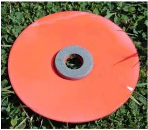
With respect to the GCPs marking two aspects were considered: the target size and its colour. According to the flight GSD, a CD disk was chosen as artificial target since its diameter guarantees enough image pixels to distinguish its shape from the background. These targets were painted in a striking redish colour. Additionally, to improve the center extraction and to overweight the target (to avoid possible displacement caused by wind) a smaller plumb washer was fixed in its center. The color contrast in the targets was useful to extract its centers. The final target design is showed in Figure 2.
Figure 2. Artificial target for UAV georeferencing.
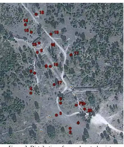
A total of 18 GCP were distributed around the hillfort enclosures with the aim to achieve a regular ground control network (Figure 3). These targets procure a low cost solution and also enable the possibility of filling the area with additional signals due to its small and optimized size and weight.
Figure 3. Distribution of ground control points.
Moreover, the GCPs coordinate measurement was made with a Leica 1200 GPS. This device is a dual frequency receiver which was used with Real Time Kinematic (RTK) method. The a priori precision of this measurement method is 1 cm in horizontal plane and 2 cm in vertical axis.
3.3 Image-based modelling
The photogrammetric workflow for image-based modelling was carried out with Photogrammetry Workbench (PW) (Gonzalez-Aguilera et al., 2012). PW is a multi-platform software which integrates photogrammetric robust algorithms with automatic and flexible approaches coming from computer vision. One of the main goals for PW is to open the interface to multiple users and disciplines, such as archaeological applications (Figure 4). The software was implemented using the C++/Qt programming language and Extensible Markup Language (XML) for data management.
This section provides an overview of the modelling pipeline which involves these main steps:
Points of interest extraction and matching
Computation of images orientation
3D dense model generation
Orthophoto generation
Figure 4. Layout of Photogrammetry Workbench software.
The first step involves the detection of the scene features and its matching in order to resolve the camera orientation. The PW software employs an ASIFT detection algorithm (Morel and
Yu, 2009) since it is invariant against the six parameters of an affine transformation.
In contrast to the other detectors commonly used, as LSM (Grün, 1985) or SIFT (Lowe, 1999), ASIFT provides more robustness in the feature identification for archaeological complex scenes.
To implement matching process, the descriptors used are the employed by SIFT detector. The descriptors are matched firstly according to the Euclidean distance (Lowe, 1999), and secondly the false matches are filtered by Moisan-Stival ORSA (Optimized Random Sampling Algorithm) (Moisan and Stival, 2004) using the epipolar geometry constraint.
After matching, relative and internal camera orientation is solved (Pierrot-Deseilligny and Clery 2011). This phase is fulfilled in two substeps. In the first one, a computer vision approach is applied, which would be refined by the well-known photogrammetric spatial resection.
So, initially relative orientation is solved for image pairs (xi, x´i) using the fundamental matrix (Hartley and Zisserman, 2003) computed by the Longuet-Higgins algorithm (Longuet-Higgins, 1981). This method is based on the independence of the fundamental matrix (F) with regard to scene structure
0 T
x Fx (1)
where each matching point is expressed in homogenous coordinates x=(x,y,1) and x´=(x´,y´,1)T. The equation (1) could be rewritten as linear equation:
0
11 12 13 21 22 23 31 32 33
x'xf + x'yf + x'f + y'xf + y'yf + y'f + xf + yf + f (2)
Known the approximate camera orientations in a relative coordinate system, a bundle adjustment (Kraus, 1997) is solved by a non-lineal least square adjustment. Calculate this spatial resection involves adding the GCPs coordinates to the mathematical model in order to geo-reference the scene.
Jointly to the camera pose (X, Y, Z, , , ), the internal camera parameters can be introduced as unknowns in the collinearity equation within the terms x, y.
The internal orientation of the camera is solved by a self-calibration method. The mathematical model considered is Fraser model (Fraser et al., 1995; Pierrot-Deseilligny and Clery 2011) which takes into account additional parameters to the Gaussian distortion model (Brown, 1971): principal distance (f), principal point coordinates (xp, yp), radial (k1, k2, k3) and tangential (p1, p2) distortion coefficients. Furthermore it considers terms for affinity (b1) and non-orthogonality (b2).
where (x´, y´) are the image coordinates referred to the principal point.
A dense surface model could be computed by means of ray intersection (Kraus, 1997; Pierrot-Deseilligny and Clery 2011). To solve this process, a SGM (Semi-Global Matching)
technique (Hirschmüller, 2008) was applied. By this means, matching each image pixel to the corresponding homologous in near images was performed.
The final 3D coordinates are calculated using the equation (5) where epipolar constraints are employed to achieve efficiency in terms of computational costs and reliability.
k i k i
x C D R X S (5)
where the k-th unknown ground point (Xk) is related to its image projection (xk) by means of the extrinsic parameters of the i-th camera parametrized by the rotation matrix (Ri) and the known projection center of each image (Si). The intrinsic parameters are the camera matrix (C) and the lens distortion function (D). From the generated 3D dense model from the oriented cameras, a true orthophoto is calculated. This process is carried out by an inverse method (Kraus, 1997) where for each pixel of the orthophoto, its corresponding image projection is computed.
4. RESULTS
The image-based modelling of the hillfort of Chamartin (Avila, Spain) from UAV photogrammetry was planned with the aim to provide to the local authorities cartographic material for heritage conservation and put in value the archaeological settlement. The study area contains complex topography due to geomorphological characteristics, and also includes vegetation features (trees and low vegetation).
A total of 49 images were captured and processed for an area of 6 ha. The image acquisition was successful due to the flight plan preset. The camera centers and its image footprint are shown in Figure 5.
Figure 5. Camera orientations of the executed flight and 3D sparse model.
Together with the camera extrinsic parameters, for this study case, the intrinsic parameters were estimated by the Fraser model. The results of self-calibration showed are in Table 3.
Parameter Value f 3266.39 pixels xp 1967.25 pixels yp 1507.60 pixels k1 -7.10 x10
-09 pixels-2 k2 3.61 x10
-16 pixels-4 k3 -4.13 x10-24 pixels-6 p1 -7.05 x10-07 pixels-1 p2 -5.00 x10-08 pixels-1 b1 7.44 x10-04
b2 4.49 x10-04
Table 3. Self-calibration parameters of Fraser model.
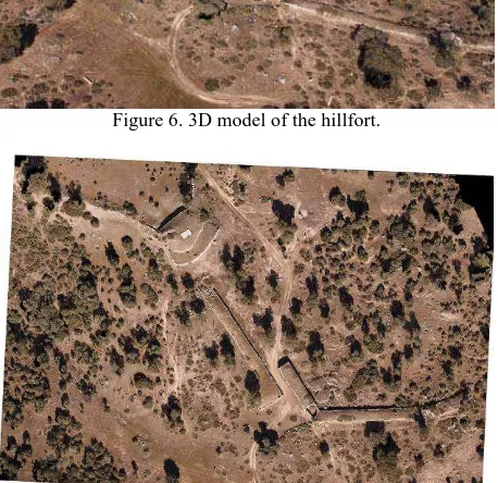
After the non-linear computation of the self-calibration, in the 29th iteration, the residual of the adjustment reached 0.68 pixels. Figure 6 shows the final point cloud which includes a total of 15.8 million points, which means, for the scenario area, an equivalent point density of 229 points/m2. The whole processing time from image orientation computation up to densification was 124 minutes. From the geo-referenced 3D model previously obtained, an orthophoto is generated at the required scale (Figure 7).
Figure 6. 3D model of the hillfort.
Figure 7. True orthophoto of the hillfort.
The validation of the final model was carried out by the calculated standard deviation, which rose up to 3.8 cm in XY and 4.9 cm in Z. These values are consistent with the a priori uncertainty computed as the composition of image GSD and the positioning error in the global coordinate frame. Our final orthophoto at 1:200 scale meets the accuracy requirements, since the planimetric error is under the threshold of 4 cm (due to the visual perception threshold).
5. CONCLUSIONS
The use of UAV images taken from a microdrone for the documentation of archaeological hillfort of Chamartin was undertaken in an effective way.
The employment of a flight planning software made easier the data acquisition, as well as it optimized the field work and guaranteed the achievement of technical project requirements. The tested PW software provided an automatic tool for rendering heritage documentation. The robust algorithms
incorporated allow coping with a wide range of study cases due to its flexibility to adapt to multiple shooting configurations. The final accuracy achieved in the study case is affected by the employment of a self-calibration of the internal camera parameters. Although, it is usual considering a laboratory camera calibration previously to field acquisition, the self-calibration enables to work in a more flexible way and extends the interval between periodical laboratory calibration.
Archaeologists are provided with 3D products in large scale to satisfy their analysis requirements, as well as with a complete dataset which can be used for other purposes such as touristic promotion, heritage preservation or web dissemination.
In order to improve the results obtained, as future perspectives, the trees will be automatically removed showing a clearer 3D model which together with an automatic hole removing, will bring a DTM with enhanced archaeological features.
References from Journals:
Álvarez-Sanchís, J.R., 2005. Oppida and Celtic society in western Spain, e-Keltoi: Journal of Interdisciplinary Celtic Studies 6, 1-31.
Baquedano Beltrán, I., Martín Escorza, C., 2007. La Edad de Hierro en La Osera,Chamartín de la Sierra, Ávila, Senderos GeoArqueológicos 4.
Brown, D., 1971. Close-range camera calibration, Photogrammetric engineering, 37, pp. 855-866.
Cabré-Aguiló, J., Cabré de Morán, E., Molinero, A., 1950. El castro y la necrópolis del hierro céltico de Chamartín de la Sierra. (Ávila), Acta Arqueológica Hispánica V.
Chiabrando, F., Nex, F., Piatti, D., Rinaudo, F., 2011. UAV and RPV systems for photogrammetric surveys in archaelogical areas: two tests in the Piedmont region (Italy), Journal of Archaeological Science, 38, pp. 697-710.
Fabián García, J.F., 1986. El bronce final y la Edad del Hierro en "Cerro del Berrueco" (Ávila-Salamanca) Zephyrus: Revista de prehistoria y arqueología 39-40, 273-287.
Fernández-Hernandez, J., González-Aguilera, D., Rodríguez-Gonzálvez, P., Mancera-Taboada, J., 2012. A New Trend for Reverse Engineering: Robotized Aerial System for Spatial Information Management, Applied Mechanics and Materials, 152, pp. 1785-1790.
González-Tablas, S., F.J. , 2008. La casa vettona. Actuaciones recientes en el castro de la Mesa de Miranda (Chamartín de la Sierra, Ávila), Zona arqueológica 12.
González-Tablas S., F.J., 2009. Las murallas de las Cogotas y la mesa de Miranda. Apuntes a la arquitectura defensiva de los vettones, Zephyrus: Revista de prehistoria y arqueología 64, 63-79.
Grün, A., 1985. Adaptive least squares correlation: a powerful image matching technique, South African Journal of Photogrammetry, Remote Sensing and Cartography, 14, pp. 175-187.
Hendrickx, M., Gheyle, W., Bonne, J., Bourgeois, J., De Wulf, A., Goossens, R., 2011. The use of stereoscopic images taken from a microdrone for the documentation of heritage – An example from the Tuekta burial mounds in the Russian Altay, Journal of Archaeological Science, 38, pp. 2968-2978.
Hernandez-Lopez, D., Felipe-Garcia, B., Gonzalez-Aguilera, D., Arias-Perez, B., 2013. An Automatic Approach to UAV Flight Planning and Control for Photogrammetric Applications: A Test Case in the Asturias Region (Spain), Photogrammetric Engineering and Remote Sensing, 79, pp. 87-98.
Hirschmuller, H., 2008. Stereo Processing by Semiglobal Matching and Mutual Information, IEEE Transactions on Pattern Analysis and Machine Intelligence, 30, pp. 328-341.
Lambers, K., Eisenbeiss, H., Sauerbier, M., Kupferschmidt, D., Gaisecker, T., Sotoodeh, S., Hanusch, T., 2007. Combining photogrammetry and laser scanning for the recording and modelling of the Late Intermediate Period site of Pinchango Alto, Palpa, Peru' Journal of Archaeological Science, 34, pp. 1702-1712.
Li, Z., Liu, Y., Walker, R., Hayward, R., Zhang, J., 2010. Towards automatic power line detection for a UAV surveillance system using pulse coupled neural filter and an improved Hough transform, Machine Vision and Applications, 21, pp. 677-686.
Longuet-Higgins, H., 1981. A computer algorithm for reconstructing a scene from two projections, Nature, 293, pp. 133-135.
Moisan, L., Stival, B., 2004. A probabilistic criterion to detect rigid point matches between two images and estimate the fundamental matrix, International Journal of Computer Vision, 57(3), pp. 201-218
Morel, J. M., Yu, G., 2009. ASIFT: A new framework for fully affine invariant image comparison, SIAM Journal on Imaging Sciences, 2, pp. 438-469.
Poirier, N., Hautefeuille, F., Calastrenc, C., 2013. Low Altitude Thermal Survey by Means of an Automated Unmanned Aerial Vehicle for the Detection of Archaeological Buried Structures, Archaeological Prospection, 20, pp. 303-307.
Wallace, L., Lucieer, A., Watson, C., Turner, D., 2012. Development of a UAV-LiDAR System with Application to Forest Inventory, Remote Sensing, 4, pp. 1519-1543.
Xiang, H., Tian, L., 2011. Development of a low-cost agricultural remote sensing system based on an autonomous unmanned aerial vehicle (UAV), Biosystems Engineering, 108, pp. 174-190.
Zhang, Y.M. , Chamseddine, A., Rabbath, C.A., Gordon, B.W., Su, C.Y., Rakheja, S., Fulford, C., Apkarian, J., Gosselin, P., 2013. Development of advanced FDD and FTC techniques with application to an unmanned quadrotor helicopter testbed, Journal of the Franklin Institute, 350, pp. 2396-2422.
References from Books:
Álvarez Sanchís, J.R., Ruiz Zapatero, G., 2001. Cementerios y asentamientos: bases para una demografía arqueológica de la Meseta en la Edad del Hierro, in: Gardes, L.B.-R.y.P. (Ed.), Entre Celtas e Iberos. Las poblaciones protohistóricas de las Galias e Hispania, Madrid, Spain, pp. 61-75.
Hartley, R., Zisserman, A., 2003. Multiple view geometry in computer vision, Cambridge University Press New York.
Kraus, K.., 1997. Advanced Methods and Applications Vol 2. Fundamentals and Standard Processes Vol 1, Dümmler, Bonn.
References from Other Literature:
Brumana, R., Oreni, D., Van Hecke, L., Barazzetti, L., Previtali, M., Roncoroni, F., Valente, R., 2013. Combined geometric and thermal analysis from uav platforms for archaeological heritage documentation. In: The ISPRS Annals of the Photogrammetry, Remote Sensing and Spatial Information Sciences, Strasbourg, France, Vol. II-5/W1, pp. 49-54.
Eisenbeiss, H., Lambers, K., Sauerbier, M., Li, Z., 2005. Photogrammetric documentation of an archaeological site (Palpa, Peru) using an autonomous model helicopter. In: XX CIPA International Symposium, Torino, Italy
Esposito, S., Fallavollita, P., Melis, M.G., Balsi, M., Jankowski, S., 2013. UAS imaging for archaeological survey and documentation. In: SPIE 8903, Photonics Applications in Astronomy, Communications, Industry, and High-Energy Physics Experiments 2013.
Fraser, C.S., Shortis, M.R., Ganci, G., 1995. Multisensor system self-calibration. In: SPIE 2598, Videometrics IV, 2.
Gonzalez-Aguilera D., Guerrero D., Hernandez-Lopez, D., Rodriguez-Gonzalvez, P., Pierrot, M. Fernandez-Hernandez, J., 2012. Silver CATCON Award. Technical Commission WG VI/2. In: XXII ISPRS Congress. Melbourne
Haarbrink, R.B., Koers, E., 2006. Helicopter UAV for photogrammetry and rapid response. In: The International Archives of the Photogrammetry, Remote Sensing and Spatial Information Sciences, Antwerp, Belgium, Vol. XXXVI-1/W44.
Lowe, D. 1999. Object recognition from local scale-invariant features, In: International Conference on Computer Vision, Corfu, Greece.
Maddalon, J.M., Hayhurst, K.J., Koppen, D.M., Upchurch, J.M., Morris, A.T., Verstynen H.A. 2013. Perspectives on Unmanned Aircraft Classification for Civil Airworthiness Standards. Report NASA/TM–2013-217969
Molinero Pérez, A., 1933. El castro de la Mesa de Miranda (Chamartín-Ávila), Boletín de la Real xsa
Rousset-Rouviere, L., Coudrain, C., Fabre, S., Baarstad, I., Fridman, A., Loke, T., Blaaberg, S., Skauli, T., 2011. Sysiphe, an airborne hyperspectral imaging system for the VNIR-SWIR-MWIR-LWIR region. In: 7th EARSeL Workshop on Imaging Spectroscopy, pp. 1-12.
Sauerbier, M., Siegrist, E., Eisenbeiss, H., Demir, N., 2011. The practical application of UAV-based photogrammetry under economic aspects. In: The International Archives of the Photogrammetry, Remote Sensing and Spatial Information Sciences, Zurich, Switzerland, Vol. XXXVIII- 1/C22.
Xiangfeng, L., Peng, C., Xiaohua, T., Shuang, L., Shijie, L., Zhonghua, H., Lingyun, L., Kuifeng, L., 2012. UAV-based low-altitude aerial photogrammetric application in mine areas measurement. In: Second International Workshop on Earth Observation and Remote Sensing Applications (EORSA), Shanghai, China, pp. 240–242.
5.1 Acknowledgements
The authors would like to thank Claudia Sánchez Martín, Ángel Hidalgo Moratinos and Ruben Jeronimo Fernández who collaborated in the field work acquisition. Also, the authors thank the County Council of Ávila for facilitating the access to the archaeological area.