HIGH PRECISION FLUXGATE CURRENT SENSOR
Dominggus Yosua Suitella.1, Dr. Ir. Djoko Windarto, MT.2 1
Student and 2Lecture of Electrical Engineering Department, Engineering Faculty, Diponegoro University Jl. Prof.Sudharto, Tembalang, Semarang
Abstract –Nowadays the necessity to measure currents in the industrial worlds has been growth to the most important
tools for proceedings controls. The classical approach of measuring current is by using a resistor and measuring the voltage drop across it. This method is fine for small currents however when the current levels increase to large values, it becomes more difficult. This is because the power dissipation in the resistor increases with the current squared.
One solution for measuring large currents is by not directly measuring the current, but by measuring a property which is directly related to the current. By measuring the magnetic field around a conductor, the current level can be accurately predicted. Fluxgate current sensor uses a high permeability magnetic core to detect magnetic fields produced by a current flow through a conductor. Prodrive B.V. develops and uses a sensor with one fluxgate winding. However there is a disadvantage presented by this structure, that is the possibility of noise and ripple injection on the primary current measurement.
In this final project, a second fluxgate winding was used to cancel the induced spurious signal on the sensing resistor. The targeted specifications of the new design are spurious signal up to 50µArms, noise performance up to 50nA/sqrt(Hz) and new operating switching frequency at 15kHz.
Key Words: Fluxgate, Current Sensor, Second Fluxgate Winding, Spurious Peak, Noise.
I. INTRODUCTION
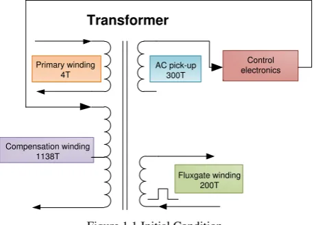
1.1 Initial Condition
The company’s current sensor uses one fluxgate winding to detect the magnetic field. And in total the sensor has 3 cores, 4 windings with their on purpose.
Control electronics Transformer
Primary winding 4T
AC pick-up 300T
Fluxgate winding 200T Compensation winding
1138T
Figure 1.1 Initial Condition
When the fluxgate is driven by square wave voltage, the voltage induces to the compensation winding, makes a square waveform at the end of transformers. It also induced to the AC pick-up winding but in opposite direction due to transformer polarity. The square wave signal from AC pick-up windings then goes through the electrical circuit to the compensation winding. At the compensation winding, both signals will add up each other. As the result there is spurious signal every harmonics switching frequency.
Initially, the current sensor has following specifications:
- Unfixed switching frequency, around 43kHz.
- Has 4 winding with 3 cores
- Noise ≤ 1µA/sqrt(Hz)
- Spurious signal ≤ 150 µArms
1.2 Objectives
The purposes of this project are:
1. Understand with Fluxgate current sensor principle.
2. Design a new system to reduce the spurious signal. Following are the target specification of the project:
- 5 windings transformer with 4 cores.
- Fixed switching frequency = 15kHz
- Noise ≤ 50nA/sqrt(Hz)
- Spurious signal ≤ 50µArms
3. Implement the design into a prototype, transformer (transformer design) and control board (schematic and PCB design).
4. Measure and qualify the finished prototype. 5. Project documentation, related to the project.
1.3 Limitations
This thesis is only discuses about Fluxgate current sensor. Other magnetic based measurement methods will only being explained briefly.
1.4 Company Profile
Prodrive B.V. was founded in 1993 by technical professionals from the Eindhoven University of Technology. The organization consists of 3 main customer-oriented departments. The Mixed Signal Group and the Digital Design Group are technological expertise centers active in the field of research and development. Complex design trajectories are executed in cross-functional development teams.
Figure 1.2 Company Structure
II. LITERATURE REVIEW
2.1 Current Measurement Technology
Generally, current measurement technology can be classified into 2 categories, namely open and closed loop sensor.
For further classification, current measurement technology can be classified into several categories based on their working principle. The working principle are based on purely electrical, magnetic, or make use of the behavior that some materials have in presence of a magnetic field. They are:
Shunt
Current Transformer
Hall-Effect Transformer
Rogowsky Transformer
Fluxgate Transformer
2.2 Fluxgate Technology
Fluxgate main principle uses a saturable inductor for sensing the field produced by an external current.
Le I n
B .o.r . . . 2.1
Figure 2.1 Electromagnet principle
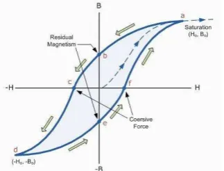
Saturation
Saturation is a state reached when an increase in applied magnetizing field H cannot increase the magnetization of the material further, so the total magnetic field B levels off.
Figure 2.2 Magnetization curve / B-H curve
As the H field increases, the B field approaches a maximum value asymptotically, the saturation level for the substance. Magnetic field is representing the existing current trough a conductor. From this idea the excited saturable inductor is able to measure current.
The saturation point of ferromagnetic materials depends on magnetic permeability and also depends on the number of current. The core permeability will change both by an external field (produced by external current IPRIM) and an exciting current (IEXCT) through the inductor.
H B
. . . 2.2
Fluxgate current sensor principle
When the inductance is charged and the core is not saturated, the current increases with a low slope (track 1). For a constant current value, the core saturates and the LIND value decreases rapidly. The signal slope is higher and the current rises very fast (track 2).
Figure 2.3 IEXCT with and without External Current
On figure 2.3 (red line), when external current is applied the inductance value is still remains high, the core is not saturate yet (track 1). Due to external magnetic field, the core saturates faster (noted with steeper current graph in track 2).
Figure 2.4 IEXCT by a saturable inductance without external field
Figure 2.4 shows the current wave form when a certain frequency voltage square wave is applied to a saturable inductor, without any external current, the value of the direct current (DC) is zero. The condition is called Zero Flux Condition. But when a current passes through the primary cable, a magnetic field appears in the system, therefore changes the symmetry of the signal (Figure 2.5).
If a magnetic field to cancel this effect is generated, the Zero Flux condition can be obtained again. Knowing the current to cancel this effect and return the system to the Zero Flux Condition means that the current passing through the primary conductor can be calculated with high precision.
2.3 Second harmonic detector
The flux gate is driven by a square wave signal that contains only odd integer harmonics. When external current flow, the magnetic field will change the shape of the total waveform which contain different shape between positive and negative polarity (asymmetry). When the signal is decomposed in the spectrum, there will be several even components due to the asymmetrical itself.
Figure 2.6 Square wave contains odd harmonics
frequency
Figure 2.7 Square wave contains odd and even
harmonics frequency
This second harmonic is a representation of the external magnetic field in the flux gate element. The higher the main current, the higher the 2nd harmonic component.
III. DESIGN AND IMPLEMENTATION
3.1 Overview
The new current sensor uses two identical fluxgate winding driven in anti-phase. Using this configuration, the second fluxgate winding is excited with an equal current but in reverse direction to the current used for exciting the first fluxgate winding canceling its effect.
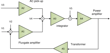
AC-pickup Amplifier
§ 3.4.2 Integrator § 3.4.4
Figure 3.1 The new current sensor overview
3.2 Transformer
The transformer composed out of 3 cores. A
Picture Legend:
Winding L1 (Blue color) is fluxgate winding #1 (200 turn) Winding L2 (Red color) is
fluxgate winding #2 (200 turn) Winding L3 (Green color) is AC
pick up winding (300 turn) Winding L4 (Orange color) is
compensation winding (1138 turn)
Figure 3.2 Transformer overview
Fluxgate Core
The Fluxgate core composed out with VitroVac 6025. It was chosen because it has high relative permeability 20.000 in order to meet the sensitivity requirement (easily saturated and desaturated by a slight change of magnetic field).
By using 2nd harmonic detector, the detection area is located at the last 50% of each half period. That means that the ideal saturation point is located in the middle of the last 50% of each half period. It can be adjusted by changing the inductance value of the winding.
The new saturation time can be determined by
using a comparison with the existing product’s
saturation time.
)
3.3 Electrical Design
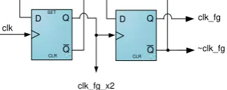
3.3.1 Clock Generator & Half Bridge
The current sensor needs 3 signals to operate. A square wave signal to drive the 1st half bridge (clk_fg), a square wave signal with 1800 phase different to drive the 2nd half bridge (~clk_fg), and a signal with 2x clk_fg frequency to drive the 2nd harmonic detector circuit.
D Q
Figure 3.3 D-Flip-Flops as the clock generator
clk_fg
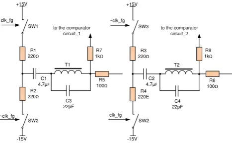
~clk_fg +15V
-15V R1 220Ω
R2 220Ω
C1 4.7µF
T1 SW1
SW2
~clk_fg +15V
R3 220Ω
R4 220E
C2 4.7µF
T2 SW3
R5
100Ω 100R6Ω
R7
1kΩ 1kR8Ω
to the comparator circuit_1
to the comparator circuit_2
-15V SW2 clk_fg C3
22pF
C4 22pF
Figure 3.4 Half Bridge Overview
3.3.2 Summation Point
One way to combine the signals from 2 fluxgate is by simply connecting both two other sides of fluxgate winding. If there is any asymmetrical occur due to primary current, the resulting current flows to the sensing resistor are twice of the subtraction of the asymmetrical itself. The currents are already in DC region.
X106
clk_fg_2x R10
1k R155k1
R16 5k1
C6 100n
C7 100n SW5
U3 R5
100E
R6 100E
R9 100E
C5 1nF
Figure 3.5 Summing point, demodulator and LPF
3.3.3 Second Harmonic Detector
The 2nd harmonic detector needs to eliminate the first 50% of each half period and pass the last 50% signal to the LPF. This is done by switching SW5 at the double clock frequency (clk_fg_x2). When SW5 is ON it will connect the fluxgate signal to the ground thus eliminate the first 50% of each half period.
3.3.5 Second Order LPF
The low pass filter is used to filter out the square wave coming out of the fluxgate detector. The new design operates at 15kHz with corner frequency at 120Hz. Using this cut-off point, it can attenuate the fluxgate signal by -65.25dB and leave 5.676mVpkpk ripple at the output.
Figure 3.6 Frequency response of the 2nd order low pass filter
The 2nd order LPF is chosen because it has more additional attenuation for frequencies higher than the cutoff frequency. The frequency above filter’s corner frequency will consistently decreases by 12dB/octave or 40dB/decade.
3.4 Control System 3.4.1 Overview
The current sensor internally consists out of 2 signal paths. High frequencies are picked up by an AC sense winding while the DC signal is picked up by the fluxgate winding.
f1 f2
dB
º
Log(f)
Log(f) 90
ACLR ACRES
Blue: DC-feedback: fluxgate Red: AC-feedback: transformer
Green: Sum
Figure 3.7 AC and DC loop
The sum of both the AC-pickup signal and the fluxgate signal should produce a flat response before being integrated. The targeted open loop response consists of a single pole at a very low frequency and then a consistent roll-off of -20dB/decade until at least 40kHz to suppress a peak at the resonant frequency (around 300kHz).
Log(f) -90º
A1 dB
º f1
Black: Targetted OL-reponse Green: OL-response if DC-gain > AC-gain
Peaking: worst case 15dB @>300kHz
Figure 3.8 Total frequency response of the current sensor
3.4.2 AC Pick-up Amplifier
The AC amplifier used to amplify small signal from AC pickup winding. The gain of the circuit is set to 40V/V. This is the maximum attainable value for the selected Opamp, OP27 (limited by GBW).
3.4.3 Fluxgate Amplifier
amplify the DC signal but still maintain the level of the noise.
3.4.4 Integrator
The integrator will most determine the stability of the system. It contains a single pole at 0.72Hz.. The gains are set to times 1000 to maintain high accuracy of the sensor.
DC gain = x1000V/V AC gain = x5000 V/V
During qualification of the existing current sensor, it was shown that the fluxgate circuit (DC-path) was the dominant noise source in the sensor (noise level was too high between 1-200Hz). Therefore to minimize the noise level, but keep maintain the accuracy, the AC-loop gain was set higher than the DC-loop gain.
3.4.5 Power Amplifier
The power amplifier will directly drive the compensation winding of the transformer. Therefore it should be able to handle the full secondary current of 15A/(1138:4=284.5 CTR )=53mA. This also means that it should be able dissipate at least 53mA*15.75V~1W. Power dissipation calculation.
mW 3.5.1 Noise calculation
Offset is mainly determined by symmetry in the electronic control circuits.
+
Figure 3.9 Opamp offset model
bias offset contributor and then converted to an equivalent offset current at the output of the power op amps.
integrator
Fluxgate amplifier Transformer AC pick-up
Power amplifier
V2
Figure 3.10 Current sensor offset sources
Table 3.1 Offset contribution
Offset Item Offset Offset gain Result Unit Name
Fluxgate 0,00 A1*A3dc*A4 0 uV
Fluxgate amplifier 171,60 A1*A3dc*A4 17331600 uV
AC pick up 30,18 A2*A3ac*A4 6036000 uV
3.5.2 Noise calculation
Noise is a random fluctuation in an electrical signal, a characteristic of all electronic circuits. Noise is generated by every component in electrical circuit and the value is varies on every components.
+
Figure 3.11 Opamp noise model
Table 3.2 Noise calculations
Input point Noise @10Hz NG Total Noise nV/sqrt(Hz) [dB] nV/sqrt(Hz)
2nd order LPF 12.899 0 12.899
FG Amplifier 21.063 40.5 2616.368805
AC Amplifier 8.61 32.26 353.0197599
Integrator 6344.895 75.56 2587998.295
Power Amplifier 15.983 6.02 5175996.59
R burden 2.309 0 5175996.59
TOTAL 5175996.59 nV/sqrt(Hz)
open loop gain 112201.854 V/A In referred to I
primary 46.131 nA/sqrt(Hz)
3.6 Test and Measurement
3.6.1 Noise and spurious peak measurement
Figure 3.12 Comparison old & new sensors (noise performance)
Old sensor peak = -126dB New sensor peak = - 114dB
1/f noise = -20dB, high frequency -10dB
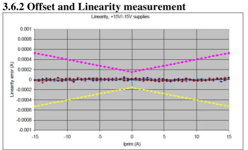
3.6.2 Offset and Linearity measurement
Figure 3.13 Offset and linearity measurement
Offset = 0.018% Linearity (see graph)
IV. CONCLUSION AND RECOMMENDATIONS
4.1 Conclusions
1. The new sensor has a better performance of noise and the spurious peak
2. Fluxgate is the dominant noise source at <100Hz
3. By using 2nd fluxgate winding, the spurious can be attenuated.
4.2 Recommendations
1. The fluxgate circuit should be designed as symmetry as possible in order to reduce the spurious peak.
2. Use component that has a better noise performance at lower frequency
REFERENCES
[1] Floyd, Thomas L. Electronic Devices Conventional Current version. Prentice Hall seventh edition, Canada, May 2009.
[2] Niese, Norman S. Control Systems Engineering. John Wiley & Sons fifth edition, California, 2009.
[3] Hashiguchi, Eiji. Non-linear magnetic circuit analysis of fluxgate curent sensor. Japan 2008. [4] Manuel Roman et al. Low Consumtion Fluxgate
Transducer. Barcelona, July 2009.
[5] PRIME Faraday Partnership. An Introduction to MEMS (Micro-electromechanical Systems). December 2001.
[6] Favre, Eric, et al. Current Sensing in Electric Drives A Future and History Based on Multiple Innovations. Switzerland. 2009.
[7] Steward, Dennis. Fluxgate Sensor Analysis. Ansoft Coorperation. Pittsburgh.
[8] Ripka, P. Current Sensors using magnetic materials. Teschnicka, Czech Republic. June 2004
BIOGRAPHY
Dominggus Yosua Suitella (L2F606021) was born in Ungaran, Mei 5th, 1988. Has finished his graduation project at Fontys University of Applied Science, Netherlands. Now, he is pursuing his bachelor degree in Diponegoro University, Indonesia.
Semarang, September 2011 Acknowledge
University Tutor
Dr. Ir. Djoko Windarto, MT