Table of Contents
Subject Index
Search
Second Edition
Corrosion Cont rol
™
1st Edition on CD-ROM
™
CASTI Publishing Inc. 10566 - 114 Street
Edmonton, Alberta T5H 3J7 Canada Tel:(780) 424-2552 Fax:(780) 421-1308
E-Mail: [email protected]
Internet Web Site: www.casti.ca
CORROSION CONTROL
Second Edition
Samuel A. Bradford, Ph. D., P. Eng.
Professor Emeritus, Metallurgical Engineering University of Alberta
Executive Editor John E. Bringas, P.Eng.
C
CASTI
CASTIPublishing Inc. 10566 – 114 Street
Edmonton, Alberta, T5H 3J7, Canada Tel: (780) 424-2552 Fax: (780) 421-1308
E-mail: [email protected] Internet Web Site: http://www.casti.ca
ii
National Library of Canada Cataloguing in Publication Data
Bradford, Samuel A. Corrosion control
Includes bibliographical references and index.
ISBN 1-894038-58-4 (bound) -- ISBN 1-894038-59-2 (CD-ROM)
1. Corrosion and anti-corrosives. I. Title.
iii
CASTI
P
UBLICATIONS
CASTI CORROSION SERIES™
Volume 1 - CASTI Handbook of Cladding Technology
Volume 2 - CASTI Handbook of Stainless Steels & Nickel Alloys Volume 3 - CASTI Handbook of Corrosion in Soils
Volume 4 - Corrosion Control
CASTI GUIDEBOOK SERIES™
Volume 1 - CASTI Guidebook to ASME Section II, B31.1 & B31.3 - Materials Index Volume 2 - CASTI Guidebook to ASME Section IX - Welding Qualifications Volume 3 - CASTI Guidebook to ASME B31.3 - Process Piping
Volume 4 - CASTI Guidebook to ASME Section VIII Div. 1 - Pressure Vessels
CASTI DATA BOOK SERIES™
CASTI Metals Black Book™ - North American Ferrous Data CASTI Metals Black Book™ - European Ferrous Data CASTI Metals Red Book™ - Nonferrous Metals CASTI Metals Blue Book™ - Welding Filler Metals
First printing, April 2001 Second printing, July 2001
ISBN 1-894038-58-4 Copyright © 2001
iv
F
ROM
T
HE
P
UBLISHER
I
MPORTANTN
OTICEThe material presented herein has been prepared for the general information of the reader and should not be used or relied upon for specific applications without first securing competent technical advice. Nor should it be used as a replacement for current complete engineering codes and standards. In fact, it is highly recommended that the appropriate current engineering codes and standards be reviewed in detail prior to any decision making.
While the material in this book was compiled with great effort and is believed to be technically correct, the authors,CASTIPublishing Inc. and its staff do not represent or warrant its suitability for any general or specific use and assume no liability or responsibility of any kind in connection with the information herein.
v
O
URM
ISSIONOur mission at the CASTI Group of Companies is to provide the latest technical information to engineers, scientists, technologists, technicians, inspectors, and other technical hungry people. We strive to be your choice to find technical information in print, on CD-ROM, on the web and beyond.
We would like to hear from you. Your comments and suggestions help us keep our commitment to the continuing quality of all our products. All correspondence should be sent to the author in care of:
CASTIPublishing Inc.,
10566 - 114 Street, Edmonton, Alberta T5H 3J7 Canada tel: (780) 424-2552, fax: (780) 421-1308
e-mail: [email protected]
B
ROWSET
HROUGHO
URB
OOKSO
NLINEwww.casti.ca
Through our electronic bookstore you can view the lite versions of all
CASTI books, which contain the table of contents and selected pages from each chapter. You can find our home page at http://www.casti.ca.
CASTI E
NGINEERING ANDS
CIENTIFICW
EBP
ORTALwww.casti.ca
vi
D
EDICATIONTo my parents,
Phariss Cleino Bradford (1905-1986) and
vii
A
CKNOWLEDGMENTSMy wife Evelin has helped me in a thousand ways by taking over duties I should have attended to, by making our home a pleasant place to work, and by providing continual encouragement for over forty years.
The publisher's appreciation is sent to all the suppliers of photographs, graphics and data that were used with permission in this book. Photographic enhancements, graphic creation and graphic editing were performed by Charles Bradford; Kevin Chu, EIT; and Michael Ling, EIT.
ix
P
REFACEHuman beings undoubtedly became aware of corrosion just after they made their first metals. These people probably began to control corrosion very soon after that by trying to keep metal away from corrosive environments. “Bring your tools in out of the rain” and “Clean the blood off your sword right after battle” would have been early maxims. Now that the mechanisms of corrosion are better understood, more techniques have been developed to control it.
My corrosion experience extends over 10 years in industry and research and 25 years teaching corrosion courses to university engineering students and industrial consulting. During that time I have developed an approach to corrosion that has successfully trained over 1700 engineers.
This book treats corrosion and high-temperature oxidation separately. Corrosion is divided into three groups: (1) chemical dissolution including uniform attack, (2) electrochemical corrosion from either metallurgical or environmental cells, and (3) stress-assisted corrosion. It seems more logical to group corrosion according to mechanisms than to arbitrarily separate them into 8 or 20 different types of corrosion as if they were unrelated.
University students and industry personnel alike generally are afraid of chemistry and consequently approach corrosion theory very hesitantly. In this text the electrochemical reactions responsible for corrosion are summed up in only five simple half-cell reactions. When these are combined on a polarization diagram, which is explained in detail, the electrochemical processes become obvious.
x
equipment design are covered in separate chapters. High-temperature oxidation is discussed in the final two chapters—one on oxidation theory and one on controlling oxidation by alloying and with coatings. Accompanying most of the chapters are questions and problems (~300 in total); some are simple calculations but others are real problems with more than one possible answer. This text uses the metric SI units (Systéme Internationale d’Unités), usually with English units in parentheses, except in the discussion of some real problems that were originally reported in English units where it seems silly to refer to a 6-in. pipe as 15.24-cm pipe. Units are not converted in the Memo questions because each industry works completely in one set of units.
For those who want a text stripped bare of any electrochemical theory at all, the starred (j) sections and starred chapter listed in the Table of Contents can be omitted without loss of continuity. However, the author strongly urges the reader to work through them. They are not beyond the abilities of any high school graduate who is interested in technology.
xi
T
ABLE OFC
ONTENTS1. Introduction 1
What is Corrosion? 2 The Cost of Corrosion 3 Safety and Environmental Factors 5 Corrosion Organizations and Journals 6
2. Basic Corrosion Theory 9
Thermodynamics 9
Electrode Reactions 10 Electrode Potentials 16 Corrosion Products and Passivity 24 Fluid Velocity 27
Temperature 28
Classifications of Corrosion 31 Electrochemical Corrosion 33
jPourbaix Diagrams 37 Corrosion Rates 44 Study Problems 48
j3. Electrochemical Corrosion Theory 53
Exchange Current Density 54 Activation Polarization 56 Concentration Polarization 59 Resistance Polarization 63 Polarization Diagrams 64 Study Problems 70
4. Metallurgical Cells 75
Metal Purity 75
Crystal Defects 77 Grain Structure 79 Solid Solution Alloys 82 Galvanic Corrosion 83
Dealloying 93
Intergranular Corrosion 98 Corrosion of Multiphase Alloys 106 Thermogalvanic Corrosion 109
Stress Cells 111
xii
5. Environmental Cells 117
Corrosive Concentration 117
j Polarization Curves 120 Crevice Corrosion 122
Pitting 127
Microbial Corrosion 131 Condensate Corrosion 137 Stray Current Corrosion 139 Study Problems 144
6. Stress-Assisted Corrosion 151
Erosion-Corrosion 152 Corrosive Wear 159 Corrosion Fatigue 163 Hydrogen Damage 166 Stress Corrosion Cracking 171 Study Problems 183
7. Corrosion in Common Environments 189
Natural Environments 189 Organic Environments 200 Mineral Acids 208 Common Inorganics 218 Study Problems 229
8. Corrosion Measurement and Failure Analysis 231
Testing 231
Inspection and Monitoring 248 Electronic Measurements 255 Failure Analysis 261 Study Problems 265
9. Materials Selection 271
Stainless Steels 272 Nickel and Nickel Alloys 281 Other Metals and Alloys 284
Plastics 294
xiii
10. Protective Coatings 313
Metal Coatings 314 Conversion Coatings 322 Organic Coatings and Linings 326 Zinc-Rich Coatings 336 Glass and Cement Coatings 338 Study Problems 341
11. Corrosion Inhibitors 345
Passivators 346
Barrier Inhibitors 350
Poisons 360
jPolarization with Inhibitors 361
Scavengers 363
Neutralizers 365
Biocides 366
Study Problems 368
12. Cathodic and Anodic Protection 371
Cathodic Protection 371 Sacrificial Protection 374 Impressed-Current Cathodic Protection 377 Anodic Protection 382
jElectrochemical Theory 387 Study Problems 389
13. Designing for Corrosion 395
Allow for Uniform Attack 396 Minimize Attack Time 396 Restrict Galvanic Cells 405 Protect Against Environmental Cells 412 Avoid Corrosive-Mechanical Interaction 416 Design for Inspection and Maintenance 422 Study Problems 424
14. Oxidation: Gas-Metal Reactions 431
jThermodynamics of Oxidation 431 Oxide Structure 433 Kinetics of Oxidation 441
Oxide Scales 445
xiv
15. Oxidation Control 467
Alloy Theory 467
High-Temperature Alloys 475 Coating Requirements 481 Oxide Coatings 481 Oxidizable Coatings 483 Study Problems 488
References 493
Chapter
1
INTRODUCTION
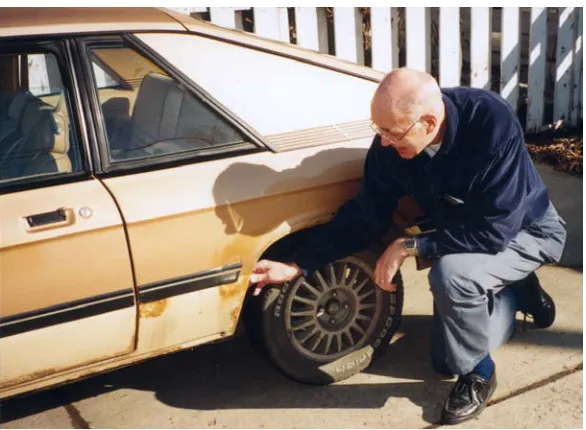
Any time corrosion comes up in casual conversation, people talk about their old cars. Everyone who owns a car over five years old has first-hand experience with rusting, along with the bitter knowledge of what it costs in reliability and resale value (see Figure 1.1). In recent years, automobile manufacturers have faced the problem and have begun to control corrosion by improving design, by sacrificial and inhibiting coatings, and by greater use of plastics.
2 Introduction Chapter 1
Chemical plants, with their tremendous variety of aqueous, organic, and gaseous corrodants, come up with nearly every type of corrosion imaginable. It becomes quite a challenge to control corrosion of the equipment without interfering with chemical processes. Petroleum refineries have the best reputation for corrosion control, partly because the value of their product gives them the money to do it correctly and partly because the danger of fire is always present if anything goes wrong. The cost of corrosion-resistant materials and expensive chemical inhibitors is considered to be necessary insurance.
Ships, especially the huge supertankers, illustrate another type of corrosion problem. Seawater is very corrosive to steel and many other metals. Some metals that corrode only slightly, such as stainless steels, are likely to crack in seawater by the combination of corrosion and high stresses. Corrosion can cause the loss of a ship and its crew as well as damage to a fragile environment. Corrosion control commonly involves several coats of paint plus cathodic protection, as well as designing to minimize stress concentration.
What is Corrosion?
Corrosion is the damage to metal caused by reaction with its environment. “Damage” is specified purposely to exclude processes such as chemical milling, anodizing of aluminum, and bluing of steel, which modify the metal intentionally. All sorts of chemical and electrochemical processes are used industrially to react with metals, but they are designed to improve the metal, not damage it. Thus these processes are not considered to be corrosion.
Chapter 1 Introduction 3
Rusting is a type of corrosion but it is the corrosion of ferrous metals (irons and steels) only, producing that familiar brownish-red corrosion product, rust.
The environment that corrodes a metal can be anything; air, water, and soil are common but everything from tomato juice to blood contacts metals, and most environments are corrosive.
Corrosion is a natural process for metals that causes them to react with their environment to form more stable compounds. In a perfect world the right material would always be selected, equipment designs would have no flaws, no mistakes would be made in operation, and corrosion wouldstilloccur—but at an acceptable rate.
The Cost of Corrosion
Everybody is certain that their problems are bigger than anyone else’s. This assumption applies to corrosion engineers also, who for years complained that corrosion is an immense problem. To see just how serious corrosion really is, the governments of several nations commissioned studies in the 1970s and 1980s, which basically arrived at numbers showing that corrosion is indeed a major problem. The study in the United States estimated the direct costs of corrosion to be approximately 4.9% of the gross national product for an industrialized nation. Of that 4.9%, roughly 1 to 2% is avoidable by properly applying technology already available—approximately $300 per person per yearwasted.
This cost is greater than the financial cost of all the fires, floods, hurricanes, and earthquakes in the nation, even though these other
natural disasters make headlines.
4 Introduction Chapter 1
Direct costs include parts and labor to replace automobile mufflers, metal roofing, condenser tubes, and all other corroded metal. Also, an entire machine may have to be scrapped because of the corrosion of one small part. Automobile corrosion alone costs $16 billion annually. Direct costs cover repainting of metals, although this expense is difficult to put precise numbers on, since much metal is painted for appearance as well as for corrosion protection. Also included is the cost of corrosion protection such as the capital costs of cathodic protection, its power and maintenance, the costs of chemical inhibitors, and the extra costs of corrosion-resistant materials.
Corrosion and corrosion control cost the U.S. Air Force over $1 billion a year.
Indirect costs are much more difficult to determine, although they are probably at least as great as the direct costs that were surveyed. Indirect costs include plant shutdowns, loss or contamination of products, loss of efficiency, and the overdesign necessary to allow for corrosion. Approximately 20% of electronic failures are caused by corrosion.
An 8-in., oil pipeline 225 miles long with a 5/8-in.-wall thickness was installed several years ago with no corrosion protection. With protection it would have had a ¼-in.-wall, which would save 3700 tons of steel (~$1 million) and actually would increase internal capacity by 5%.
Corrosion leads to a depletion of our resources—a very real expense, but one that is not counted as a direct cost. It is estimated that 40% of our steel production goes to replace the steel lost to corrosion. Many metals, especially those essential in alloying, such as chromium and nickel, cannot be recycled by today’s technology. Energy resources are also lost to corrosion because energy must be used to produce replacement metals.
Chapter 1 Introduction 5
engineer or technologist because it is a quick way for him/her to get to know the people, the plant operation, and its problems. Then, if they are any good they get promoted, and the learning cycle has to begin again with another inexperienced trainee.
Safety and Environmental Factors
Not all corrosion is gradual and silent. Many serious accidents and explosions are initiated because of corrosion of critical components, causing personal injury and death. Environmental damage is another danger; oil pipeline leaks, for example, take years to heal.
A few years ago the corrosion failure of an expansion joint in a chemical plant in England released poisonous vapors that killed 29 people.
Too often engineers take their cue from management whose motto is “Profit is the name of this game.” For engineers, getting the job done well and safely must take precedence over cost. Certainly, cost is a consideration; any engineer who uses tantalum in a situation that could be handled by steel deserves to be fired. But where tantalum is needed, an engineer who takes a major risk by gambling with steel should be kicked out of the profession.
The stated goals of NACE International (National Association of Corrosion Engineers) are:
• Promote public safety.
• Preserve the environment.
• Reduce the cost of corrosion.
Chapter
2
BASIC CORROSION THEORY
Thermodynamics
Engineering metals are unstable on this planet. While humans thrive in the earth’s environment of oxygen, water, and warm temperatures, their metal tools and equipment all corrode if given the opportunity. The metals try to lower their energy by spontaneously reacting to form solutions or compounds that have a greater thermodynamic stability.
The driving force for metallic corrosion is the Gibbs energy change,
∆G, which is the change in free energy of the metal and environment combination brought about by the corrosion. If a reaction is to be spontaneous, as corrosion reactions certainly are,∆Gfor the process must be negative. That is, the energy change must be downhill, to a lower energy.
10 Basic Corrosion Theory Chapter 2
In corrosion measurements, the driving force is more often expressed involts(V), which can be found from the equation:
E=
nF G
∆
− (2.1)
whereEis the driving force (in volts, V) for the corrosion process,nis the number of moles of electrons per mole of metal involved in the process, and F is a constant called the “faraday,” which is the electrical charge carried by a mole of electrons (or 96,490 C). Remember that joules = volts ✕ coulombs. With∆G being negative and with the minus sign in Equation 2.1, spontaneous processes always have a positive voltage,E.
Electrode Reactions
Aqueous corrosion is electrochemical. The principles of electrochemistry, established by Michael Faraday in the early nineteenth century, are basic to an understanding of corrosion and corrosion prevention.
The Corrosion Cell
Every electrochemical corrosion cell must have four components.
1. The anode, which is the metal that is corroding.
2. The cathode, which is a metal or other electronic conductor whose surface provides sites for the environment to react.
3. The electrolyte (the aqueous environment), in contact with both the anode and the cathode to provide a path for ionic conduction.
Chapter 2 Basic Corrosion Theory 11
The components of an electrochemical cell are illustrated schematically in Figure 2.1. Anodes and cathodes are usually located quite close to one another and may even be on the same piece of metal. If any component were to be missing in the cell, electrochemical corrosion could not occur. Thus, analyzing the corrosion cell may provide the clue to stopping the corrosion.
anode cathode
electrolyte (ion conductor) e
-A
C
electrical connection (electron conductor)
Figure 2.1 The components of an electrochemical corrosion cell.
Anode Reactions
Corrosion reactions can be separated into anode and cathode half-cell reactions to better understand the process. The anode reaction is quite simple—the anode metal M corrodes and goes into solution in the electrolyte as metal ions.
M→Mn++ne− (2.2)
where n is the number of electrons (e−) released by the metal. Chemists call this an “oxidation,” which means a loss of electrons by the metal atoms. The electrons produced do not flow into the solution1
but remain behind on the corroding metal, where they migrate through the electronic conductor to the cathode, as indicated in Figure 2.1.
12 Basic Corrosion Theory Chapter 2
For example, if steel is corroding, the anode reaction is
Fe→Fe2++ 2e− (2.3)
or if aluminum is corroding the reaction is
Al→Al3++ 3e− (2.4) Cathode Reactions
The cathode reaction consumes the electrons produced at the anode. If it did not, the anode would become so loaded with electrons that all reaction would cease immediately. At the cathode, some reducible species in the electrolyte adsorbs and picks up electrons, although the cathode itself does not react. Chemists call this a “reduction” because the valence of the reactant is reduced.
Since it is the corrosive environment that reacts on the cathode, and many different corrosives can attack metals, several cathode reactions are possible.
1. The most common reaction is the one seen in nature and in neutral or basic solutions containing dissolved oxygen:
O2+ 2H2O + 4e−→4OH− (2.5)
For example, oxygen in the air dissolves in a surface film of water on a metal surface, picks up electrons and forms hydroxide ions which then migrate toward the anode.
Workmen have collapsed and suffocated after entering rusting storage tanks. The O2content of the air inside can be depleted to only
5% or less.
2. The next most important reaction is the one in acids.
2H++ 2e−→H
Chapter 2 Basic Corrosion Theory 17
salt bridge
V
M Pt
H2
1M M+ 1M H+
Figure 2.3 Arrangement for measuring standard emf of a metal against the standard hydrogen electrode.
While real corrosion processes are very unlikely to take place in 1 M
solutions and almost never reach equilibrium, the standard series is useful in identifying anode and cathode reactions along with a rough estimate of how serious a driving force (voltage) the corrosion cell has.
Chemistry teachers often point out that copper will not corrode in hydrochloric acid (HCl) because the copper reduction potential is above hydrogen on the standard series. But a skeptical student who puts a penny in an open beaker of HCl finds that the copper does
slowly corrode. Oxygen from the air dissolves in the acid, making the O2+ H+cathode reaction (2.7) possible with Eo= 1.229 V, well above
Chapter 2 Basic Corrosion Theory 27
Fluid Velocity
The relative velocity between metal and environment can profoundly affect the corrosion rate. Either metal or environment can be moving: the metal in the case of a boat propeller, or the environment in the case of a solution flowing through a pipe.
Going from stagnant conditions to moderate velocities may lower corrosion by distributing a more uniform environment through the system. If inhibitors have been added, they also can be distributed more evenly and, therefore, may be more effective. In addition, moderate velocities can prevent suspended solids from settling out and creating crevice corrosion situations under the sediment. A more uniform environment also reduces the possibility of pitting.
On the other hand, increasing velocity may increase the supply of reactant (usually O2) to the cathodes. Because the diffusion of the
reactant is often the rate-controlling (i.e., slowest) step in the whole corrosion process, the corrosion rate of an active metal commonly increases with increasing velocity, until the velocity gets so high that diffusion is no longer rate controlling. This situation is illustrated in Figure 2.6a.
28 Basic Corrosion Theory Chapter 2
Figure 2.6 Effect of velocity on corrosion rate.
(a) Diffusion-controlled corrosion of an active metal with soluble corrosion products. (b) Active-passive metal. (c) Metal protected
by a thick scale of corrosion product.
For metals that are protected by a thick layer of corrosion product, the corrosion rate may be satisfactory at low velocities but above a critical velocity the protective layer will be eroded away (see Figure 2.6c).
The critical velocity for copper in seawater is only 0.6-0.9 m/s (2-3 ft./sec.), but admiralty brass, a copper alloy developed particularly for seawater, is good up to 1.5-1.8 m/s (5-6 ft./sec.).
For the rather uncommon corrosion processes under anodic control, where corrosion occurs as fast as the metal atoms can detach themselves from the surface, the velocity of the solution has practically no effect on corrosion.
Temperature
Chapter 2 Basic Corrosion Theory 31
A new hydrofluoric acid plant designed to use concentrated H2SO4at
120°C (250°F) showed high corrosion rates of the carbon steel equipment right from start-up. A renowned corrosion engineer was called in and spent several hours observing the production by looking over the operators’ shoulders. He then informed the astounded engineers that the operators were actually running at 165°C (325°F). As Yogi Berra has said, “You can observe a lot just by watching.”
Classifications of Corrosion
Corrosion takes on different appearances depending on the metal, the corrosive environment, the nature of the corrosion products, and all the other variables, such as temperature, stresses on the metal, and the relative velocity of the metal and the environment. It is easiest to differentiate the types of corrosion by the environment that is doing the attacking: aqueous liquids, nonaqueous liquids, or gases.
With aqueous liquids, corrosion is nearly always electrochemical. In electrochemical corrosion, the attack is most often approximately uniform over the entire surface of the metal that contacts the liquid. However, much more rapid corrosion occurs if differences in metallurgical composition set up an electrochemical cell, as discussed in detail in Chapter 4, or if environmental differences set up a cell, described in Chapter 5. The most serious types of corrosion, the disasters, develop when stress assists the corrosion (Chapter 6).
In rare instances, aqueous corrosion is not electrochemical. An example would be corrosion of a graphite/aluminum metal matrix composite (MMC) that was made by pouring molten aluminum around graphite fibers. In bonding with the fibers, the aluminum forms a film of aluminum carbide that may later react with an aqueous solution, thus:
Chapter 2 Basic Corrosion Theory 33
Figure 2.9 Example of corrosion of metal (bronze pump impeller) in organic liquid.
(From C.P. Dillon, Ed., Forms of Corrosion: Recognition and Prevention, NACE Handbook 1, p. 86, 1982. Reprinted by permission, National Association of Corrosion Engineers.)
Electrochemical Corrosion
Uniform Attack
34 Basic Corrosion Theory Chapter 2
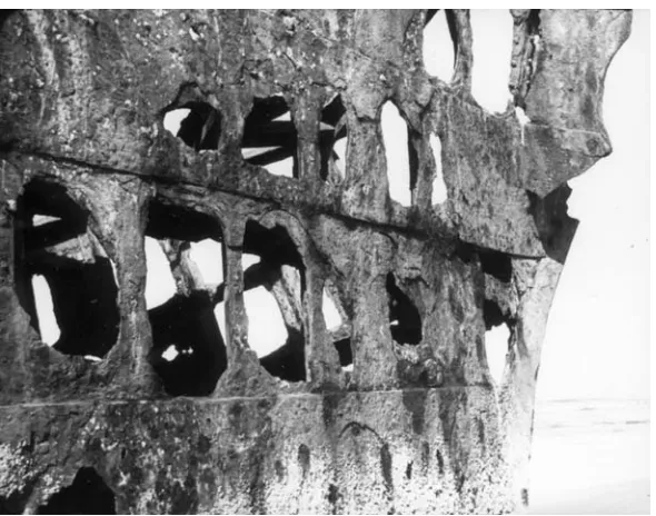
and while holes appear in only a few spots at first, all of the remaining steel is paper thin. An example of uniform corrosion is shown in Figure 2.10.
Figure 2.10 This ship ran aground near the mouth of the Columbia River 60 years earlier.
Chapter 2 Basic Corrosion Theory 37
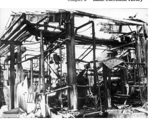
Figure 2.12 A small steam separator fractured in this gas plant. One man died and one was burned severely.
j
Pourbaix Diagrams
In 1938 Dr. Marcel Pourbaix presented his potential-pH diagrams to illustrate the thermodynamic state of a metal in dilute aqueous solutions. The advantages of depicting all the thermodynamic equilibria in a single, unified diagram was immediately evident to scientists and engineers, especially in corrosion, hydrometallurgy, and electrochemistry.
38 Basic Corrosion Theory Chapter 2
For regions where metal ions are stable, the boundaries are usually drawn for equilibrium concentrations of 10-6M, chosen to show the
limits of corrosion where soluble corrosion products would be barely detectable. However, in a specific corrosion situation, where solution concentrations are known to be greater than 10-6M or the
temperature is not 25°C (77°F), the diagram can be redrawn to fit the real conditions.
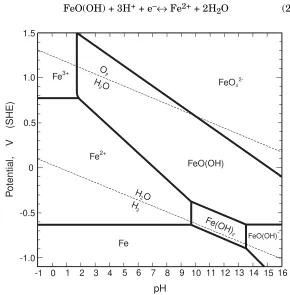
The potential-pH diagram for the iron-water system is shown in Figure 2.13. The dotted lines on the diagram show the theoretical limits of the stability of water. The upper line shows where O2should
be generated on an anode and the lower line shows where H2should
be given off at a cathode. Between the two dotted lines water is stable, so this is the important region in aqueous reactions. However, the actual stability range for water is usually much greater than the diagram indicates; water does not decompose as readily on most metals as it theoretically does on an ideal platinum surface. The H2/H2O overpotential is usually less than 0.1 V but the O2/H2O
overpotential is usually around 0.3 – 0.4 V because the reaction is always irreversible.
Aside from the stability limits for water, Pourbaix diagrams have three different types of lines.
1. Horizontal lines, independent of pH. The equilibrium does not involve hydrogen ions. For example, the boundary between the Fe3+and Fe2+regions is for the equilibrium
Fe3++ e–↔Fe2+ (2.8)
with the Nernst equation giving
Chapter 2 Basic Corrosion Theory 39
2. Vertical lines, not involving oxidation or reduction. The boundary between the Fe2+and Fe(OH)2regions shows the equilibrium
Fe2++ 2H2O↔Fe(OH)2+ 2H+ (2.20)
Iron remains in the +2 valence state with no electrons exchanged, so the reaction can take place at any potential, positive or negative.
3. Sloping lines, involving both hydrogen ions and electrons. The boundary between Fe2+ and FeO(OH) regions represents the
44 Basic Corrosion Theory Chapter 2
Other information can be superimposed on a Pourbaix diagram, as shown in Figure 2.16, to reveal more than simply regions of corrosion, passivation, and immunity.
Figure 2.16 Iron-water Pourbaix diagram showing regions where stress corrosion cracking and chloride pitting could occur. (From R.W. Staehle, Parkins Symposium on Fundamental
Aspects of Stress Corrosion Cracking, 1992. Reprinted by permission, The Metallurgical Society.)
Corrosion Rates
Chapter
3
jELECTROCHEMICAL
CORROSION THEORY
The driving force for corrosion is the potential difference developed by the corrosion cell
Ecell= Eredcat − anode red
E (2.17)
However, the cell potential does not correctly predict the corrosion rate, and it is the corrosion rate that is the essential determiner of a metal’s suitability in a corrosive environment. Logically, if the cell potential is small, the corrosion rate will be low. On the other hand, a large cell potential does not necessarily mean that the metal must corrode badly. It may passivate, for example, and corrode at an extremely low rate.
Corrosion kinetics, therateof the electrode reaction, is related to the thermodynamic driving force that is measured by the cell potential. This relationship depends on several factors, all connected with the “polarization” of the electrodes in the cell.
54 Electrochemical Corrosion Theory Chapter 3
describe the additional voltage that must be applied to overcome the polarization of the electrodes. An understanding of the causes of polarization is essential to an understanding of corrosion.
Exchange Current Density
An electrodeat equilibrium with its environment has no net current flow to or from the surface of the metal. Actually, a “dynamic equilibrium” is established in which the forward and reverse reactions are both occurring, but at equal rates. If the forward reaction is
M→Mn++ne− (2.2)
with positive current (Mn+ions) flowing from the electrode, an exactly
equal current flows back onto the surface as the metal plates back on:
Mn++ne−→M (3.1)
Thus the net current flow is zero. The oxidation process is exactly reversed by its corresponding reduction process.
In terms of the current,
Iox=Ired (3.2)
In this equationIis the current in amperes (A) and the subscripts ox and red refer to oxidation and reduction. This equilibrium current, either Iox or Ired, is called the exchange current Io. The exchange
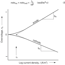
current cannot be measured directly but can be found by extrapolation, as is shown in Figure 3.1. The exchange current may be extremely small but it is not zero.
Often it is more convenient to use the exchange current density io
expressed as amperes per square metre (A/m2), rather than the
Chapter 3 Electrochemical Corrosion Theory 55
exchange current density is a direct measure of the electrode’s oxidation rate or reduction rate at equilibrium.
rateox= ratered=
nF io
(mol/m2·s) (3.3)
b
b
c
a
Log current density, (A/m )i 2
Ov
er
voltage
,
ηA
anode
cathode
io
+
0
Figure 3.1. Experimentally measurable anodic and cathodic polarization curves showing activation polarization. Tafel slopes arebaandbc. Exchange current density isio.
The term io is a function of the reaction, the concentration of
56 Electrochemical Corrosion Theory Chapter 3
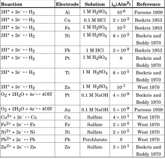
Table 3.1 Approximate Exchange Current Densities at 25°C (77°F)
Reaction Electrode Solution io(A/m2) Reference
2H++ 2e−↔H2 Al 1 M H2SO4 10-6 Parsons 1959 2H++ 2e−↔H2 Cu 0.1 M HCl 2×10⁻³ Bockris 1953
2H++ 2e−↔H2 Fe 1 M H2SO4 10-2 Bockris 1953 2H++ 2e−↔H2 Ni 1 M H2SO4 6×10⁻² Bockris and
Reddy 1970 2H++ 2e−↔H2 Pb 1 M HCl 2×10⁻⁹ Bockris 1953 2H++ 2e−↔H2 Pt 1 M H2SO4 8 Bockris and
Reddy 1970 2H++ 2e−↔H2 Ti 1 M H2SO4 6×10⁻⁵ Bockris and Reddy 1970 2H++ 2e−↔H2 Zn 1 M H2SO4 10-7 West 1970 O2+ 2H2O + 4e−↔4OH− Pt 0.1 M NaOH 4×10⁻⁹ Bockris and
Reddy 1970 O2+ 2H2O + 4e−↔4OH− Au 0.1 M NaOH 5×10⁻⁹ Parsons 1959 Cu2++ 2e−↔Cu Cu Sulfate 4×10⁻¹ West 1970 Fe2++ 2e−↔Fe Fe Sulfate 2×10⁻⁵ West 1970 Ni2++ 2e−↔Ni Ni Sulfate 2×10⁻⁵ West 1970 Pb2++ 2e−↔Pb Pb Perchlorate 8 West 1970 Zn2++ 2e−↔Zn Zn Sulfate 3×10⁻¹ Bockris and
Reddy 1970
Note that a platinum surface makes the H2 reaction extremely easy, but not the O2 reaction. The io values for corroding and plating metals are obviouslynotin the same order as their standard electrode potentials,E°.
Activation Polarization
Chapter 3 Electrochemical Corrosion Theory 63
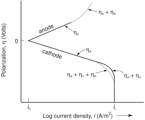
Resistance Polarization
An additional overpotential, the resistance polarization ηR, is
required to overcome the ohmic resistance of the electrolyte and any insoluble product film on the surface of the metal. This overpotential is defined by Ohm’s Law as
ηR=IR (3.10)
where I is the current and R is the resistance, in ohms (Ω), of the electrolyte path between anode and cathode and is directly proportional to the path length. In typical corrosion processes, the anodes and cathodes are immediately adjacent to each other so that resistance polarization makes only a minor contribution to the overall polarization, as indicated in Figure 3.5.
0
cathode
anode
Log current density, (A/m )i 2
P
olar
ization,
(V
olts)
η
iO iL ηA
ηA
ηA+ηR
ηA+ηC+ηR ηA+ηC
Figure 3.5 Polarization curves for anode and cathode reactions showing contributions for activation,ηA, concentration polarization
Chapter
4
METALLURGICAL CELLS
Corrosion can change from uniform corrosion to a localized attack because of differences in the metal or because of variations in the environment. This chapter deals with the metallurgical differences and the types of corrosion resulting from them.
The important principle to remember is that corrosion attacks inhomogeneities in the metal. Real metals contain many inhomogeneities, most of them deliberately put in to achieve high strength. A perfectly pure metal crystallized in a perfect crystal structure would be both incredibly strong and highly corrosion resistant, but no such metal exists.
Metal Purity
Commercially pure metals typically contain a few tenths of 1% of impurities. These small amounts of extraneous atoms do not appear to have much effect on corrosion in natural environments such as soil and water, but they do affect the protective nature of the oxide scale in atmospheric corrosion.
In steels, the normal impurities do not change the corrodibility of the metal if the aqueous environment is between pH 4 and 13.5, but in acids, sulfur and phosphorus in the steel increase attack by making H2gas generation easier. Copper in steel also increases corrosion in
76 Metallurgical Cells Chapter 4
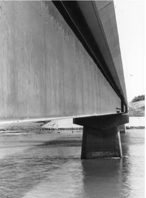
alloying with a few tenths of a percent of Cu, Ni, and Cr. Figure 4.1 illustrates a typical application of weathering steel.
Figure 4.1 Bridge girder of high-strength, low-alloy weathering steel.
(Courtesty of Charles N. Bradford.)
In recent years it has been found that extremely high-purity metals are extraordinarily resistant to corrosion. For example, 99.998% Al corrodes at only 1/30,000ththe rate of commercial 99.2% Al.
Chapter 4 Metallurgical Cells 77
Crystal Defects
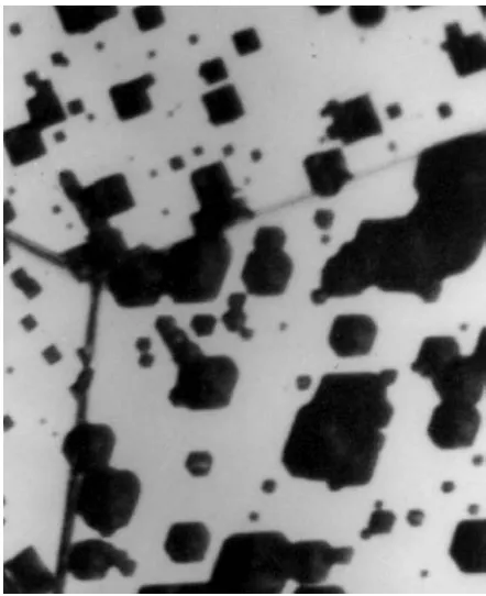
Although metals are crystalline, the crystal structures are not perfect. In addition to impurity atoms, they all contain many atom vacancies, that is, sites where atoms should be present but are not. The vacancies permit some diffusion of atoms within the crystal. In addition, all real crystals contain linear flaws called “dislocations,” where atoms are crowded too closely on one side of the line and are packed too loosely on the other side. These dislocation lines give the metal ductility but they also increase diffusion and corrode more rapidly than the surrounding crystal, as shown in Figure 4.2.
Figure 4.2 Etch pits in 3% silicon steel. Ferric sulfate solution has eaten out the distorted structure around dislocation lines where they intersect the metal surface. Magnification 1820X.
(From Metals Handbook, 8thed., Vol.8, page 113, 1973.
78 Metallurgical Cells Chapter 4
Cold Work
Cold work (rolling, hammering, drawing, etc.) is usually done at room temperature, although it can be at any temperature below the metal’s recrystallization temperature. While cold work strengthens the metal at very little cost, it greatly increases vacancy and dislocation densities. Impurities can then concentrate at the dislocations to create very localized corrosion cells that contribute to pitting. In acidic corrosion, cold working can increase H+ adsorption sites at
dislocations on the metal surface. Cold work also introduces internal stresses that make the metal more susceptible to stress corrosion cracking. Figure 4.3 shows the surface of cold-worked brass after it has been polished and etched with acid, revealing some of the dislocation lines and grain boundaries.
Chapter 4 Metallurgical Cells 79
Grain Structure
Grain Size
The metal “grains,” the individual crystals, should be extremely small to give the best toughness, but that means that the grain boundaries, which are narrow regions of mismatch between the grains (see Figure 4.4), will be numerous and take up an appreciable fraction of the metal surface.
Atoms at the grain boundaries are easily corroded because they are not bonded as strongly as atoms within the grains. More importantly, the grain boundaries serve as collecting sites for impurity atoms that do not fit well inside the crystals. At moderate temperatures, diffusion is much more rapid along the boundaries than within the grains, so atoms collect more rapidly and form precipitates at the boundaries. All these inhomogeneities localize the corrosion attack.
Grain Shape
Cold work severely distorts the shape of the metal grains; rolling, for example, flattens the grains and elongates them in the rolling direction as in Figure 4.4b. A transverse cut of the same metal shows that the grains have been particularly flattened in the vertical, or “short transverse” direction, but the grain boundaries are not lined up the way they are in the long transverse or the longitudinal (rolling) directions.
80 Metallurgical Cells Chapter 4
Figure 4.4 Photomicrographs of metal grain structures. (a) Grain boundaries in an annealed iron (130X). (b) Rolled surface (R), longitudinal (L), and transverse (T) sections of low-carbon steel cold-rolled 65% (330X). RD is the rolling direction. (From J.T. Michalak,
Metals Handbook, 8thed., Vol. 8, p. 220, 1973. Reprinted by
Chapter 4 Metallurgical Cells 87
Figure 4.6 The area effect in galvanic corrosion. (a) Steel plates with copper rivets in seawater 15 months. (b) Copper plates with steel rivets, same environmental conditions. (From Corrosion in Action,
p. 18, 1955. Reprinted by permission, Inco Alloys International.)
88 Metallurgical Cells Chapter 4
The Distance Effect
In environments with low electrical conductivity, such as fresh water, galvanic corrosion occurs only near the connection point where the two metals make contact. The high resistivity of the solution confines the cell current to the region around the junction, causing a deep ditch to form in the anode metal where it touches the cathode. Attack in a narrow band on only one side of a metal junction confirms a diagnosis of galvanic corrosion. This “distance effect” offers another way to combat galvanic corrosion: space anode and cathode far enough apart and galvanic corrosion will virtually cease even though the metals are still electrically connected by an external conductor. In effect, that is what painting both the anode and the cathode does, by increasing the electrical resistance through the fine, winding paint pores.
Chapter 4 Metallurgical Cells 89
insulator
copper steel water flow
grounding strap
Figure 4.7 Insulated connector between steel and copper pipes, shorted by a grounding strap.
New Metal/Old Metal Galvanic Corrosion
Connecting new pipe, fresh from the mill, to old pipe of the same composition sets up a galvanic cell, corroding the new pipe severely. This often happens where a short section of a buried pipeline is replaced. The new pipe corrodes at a faster rate than the old pipe, as illustrated in Figure 2.4b where Rate 1 is much greater than Rate 2. The large cathode/anode area ratio makes the situation even worse.
For above-ground storage tanks, after an old tank bottom has corroded too much to be repaired, common practice is to pour in a layer of clean sand and weld in a new bottom. This sets up a bad galvanic cell that can only be stopped by installing cathodic protection anodes between the two bottoms. Another example: scoring from a pipe wrench removes protective corrosion products, and with the high cathode/anode area ratio, concentrates attack at the gouges on the metal surface.
Chapter 4 Metallurgical Cells 97
Figure 4.13 Graphitic corrosion of cast iron elbow. (From Corrosion in Action, p. 6, 1955. Reprinted by permission,
Inco Alloys International.)
“Graphitized” pipe looks like rusty pipe. Its shape is unchanged; even the manufacturer’s trademark cast into the pipe can still be read. If it has not been broken, the pipe can still carry water at internal pressures of up to around 3.5 MPa (500 psi), and packed in soil it may give good service. But being weak and brittle, it will break from frost heave, from water hammer, or any other mechanical stress.
Many a building has burned to the ground because the sudden change in water pressure for fire fighting has broken the water mains.
98 Metallurgical Cells Chapter 4
One test for graphitic corrosion is the famous Clang and Clunk Test: Hit the pipe with a hammer. If the metal goes “clang,” it is good. If it goes “clunk,” or breaks, it is not.
Ductile, malleable, and white cast irons don’t undergo graphitic corrosion because they don’t have a graphite network (Figure 4.12) that would hold the corrosion products in place. Graphitic corrosion is sometimes called “graphitization,” (sic) but real graphitization occurs at high temperatures where carbon deposited on the surface diffuses into steel and embrittles it.
Intergranular Corrosion
Galvanic corrosion at the grain boundaries, although on a microscopic scale, is caused by compositional differences between the grain boundaries and the metal adjacent to the boundaries. The boundaries are collection sites for a great number of ill-fitting atoms that would distort the crystals if left inside, as indicated in Figure 4.14. Diffusion is rapid along the boundaries so that new phases can form rapidly, and the new phases do not require additional energy to produce new surfaces as they would within the crystals. An example of intergranular corrosion leading to a stress corrosion cracking failure is shown in Figure 6.14.
Sensitization of Stainless Steels
Chapter 4 Metallurgical Cells 109
Figure 4.19 Ringworm corrosion of oil well tubing. (From Corrosion Control in Petroleum Production, TPC Publication No. 5, p. 15, 1979.
Reprinted by permission, NACE International.)
Thermogalvanic Corrosion
Hot atoms in a metal vibrate more vigorously and thus are more weakly bonded than cold atoms. Consequently, the hot end of a pipe is likely to be anodic to the colder, more cathodic end. But this is an oversimplification. Other factors must be considered: the amount of temperature difference, the distance between hot and cold ends, possible plating out of metal atoms, possibility of passivation, and heat transfer conditions.
Differential Temperature Cells
110 Metallurgical Cells Chapter 4
In theory, the hot metal should be more reactive than the cool metal if both are active or both are passive, but in many cases the temperature difference is no more than 75°C (135°F), which creates a potential difference of only a few millivolts. However, copper alloys will corrode if the temperature difference is 65°C (117°F) or more, with the hot end being the anode. The closer the hot and cold ends are to each other and the better the electrical conductivity of the electrolyte, the more severe the differential temperature cell becomes, due to the distance effect.
Active-Passive Galvanic Cells
If the difference in temperature changes the character of passive surface films, even small temperature differences can create severe galvanic cells. A metal that passivates at low temperatures but becomes transpassive at high temperatures will corrode seriously at the hot location, with the colder, passivated metal serving as cathode. On the other hand, if corrosion conditions are not severe enough to passivate the metal at low temperatures but will passivate at high temperatures, the cold end corrodes.
Most household hot water tanks were galvanized steel at one time. The zinc was anodic to steel in the 60°C (140°F) water. With the advent of automatic washing machines, water temperatures had to be raised to 80°C (175°F), which passivated the zinc and destroyed the steel by galvanic action. Glass-lined or Monel (Cu-Ni alloy) tanks are now used, or cathodic protection is applied.
Chapter 4 Metallurgical Cells 111
Cathodic Plating
A few metals, notably copper, silver, and lead, may even contribute another cathode reaction to the corrosion: they may plate out at the cathode. Copper in water, for example, adds the reaction
Cu2++ 2e−→Cu°↓ (2.9)
at the cold metal in addition to the usual cathode reaction of oxygen reduction. Diffusion of the copper ions is slow, though, so the process usually requires a solution flowing from hot end to cold end to transport the ions.
Aluminum cannot be plated from aqueous solution. Iron, nickel, and usually zinc, cadmium, and tin, have high overvoltages and do not plate out, either.
Surface Temperatures
Bear in mind that the surface temperature of the metal is often hotter than the process fluid. The actual skin temperature is much more important than either the total amount of heat transfer or the temperature of the environment.
Heat transfer situations can by tricky. For example, one engineer was chagrined to find that a steel heater that held boiling tar acid corroded four times as fast as the test he had made with a steel sample just immersed in the stuff.
Stress Cells
112 Metallurgical Cells Chapter 4
Figure 4.20 Variation in corrosion of a stainless steel spring from a sulfuric acid pump, caused by differences in stress along the spring.
Plastic deformation produced by cold work increases dislocation density greatly as well as leaving residual internal stresses in the metal. Corrosion attacks the deformed surfaces, although the corrosion potential may not shift greatly (~40 mV is typical), because both anodic and cathodic process are stimulated. Figure 4.21 shows localized corrosion of the cold-formed head and point of a nail.
regions of local stress
Figure 4.21 Anodic regions revealed in the corrosion of a nail. The shank acts as a cathode.
Chapter
5
ENVIRONMENTAL CELLS
One drop of water sitting on a metal surface creates an electrochemical cell. The metal may be approximately uniform in composition but the water drop is not, and that is all that is required to start localized attack. The environment needs only to vary in concentration, velocity, or temperature to set up local anode and cathode areas on the metal. The cathodes, of course, will be where the environment reacts best. More corrosion in industry is caused by concentration cells than from any other cause.
Corrosive Concentration
Oxygen Concentration Cells
The most common cathode reaction of all is the reduction of oxygen from the air.
O2+ 2H2O + 4e−→4OH− (2.5)
118 Environmental Cells Chapter 5
Figure 5.1. Diagram of corrosion of metal under a water droplet.
Any place that the metal contacts solution having an exceptionally high oxygen concentration will be a cathode, and any place where the oxygen is especially low will tend to be anodic, if it is not located too far from the cathode. The distance effect is always important in electrochemical cells, as is the cathode/anode area ratio.
An inspection of old highway culverts by the Wyoming Highway Department found that most corrosion occurred in the center of the culvert pipes under the paving centerline, where the oxygen concentration in the soil was at its lowest.
Other Concentration Cells
While oxygen concentration cells are the most common, any cathode reactant that varies in concentration on the metal surface can create a corrosion cell. A variation in pH, for example, can establish a cathode region where pH is low, provided it is low enough (perhaps below pH 4) to make hydrogen reduction (Reaction 2.6) an important cathode process.
If corrosion is caused by a strong oxidizer, the cathodes will tend to be located at regions of high oxidizer concentration. Oxidizers commonly used in the chemical industries include O2, ozone (O3), nitric acid
Chapter 5 Environmental Cells 119
solutions containing ferric ion (Fe3+), chromate (CrO42−), dichromate
(Cr2O72−), permanganate MnO4−), or perchlorate (ClO4−).
Offshore drilling platforms have two oxygen concentration cells on each leg. The first is in the splash zone and just below the water surface. Corrosion is moderate at lower depths. The second concentration cell is at the mud line where the O2 concentration is
much higher in the water than in the mud (see Figure 5.2).
mean tide level severe corrosion
severe corrosion low corrosion mud
0.1 mm/y
Figure 5.2 Oxygen concentration cells on legs of offshore steel structure.
Critical Humidity
124 Environmental Cells Chapter 5
Automobiles used to have bolted-on fenders to make replacement easier. Canvas gaskets between fenders and body prevented squeaking, but once moisture got through the paint to the canvas, the fenders tended to fall off.
When liquid is flowing outside, crevices must be quite tight (in the order of a micron) (<0.1 mil) to keep the solution inside stagnant. Chloride ions speed the development of corrosion in the crevice, but even so, a long incubation period precedes any localized attack. Within the crevice the metal commonly looks like it has pitted, as Figure 5.8 shows on a stainless steel flange. Stainless steels are particularly susceptible because they become active within the crevice and passive outside, developing a large potential difference between anode and cathode areas. Crevice corrosion often initiates stress corrosion cracking or corrosion fatigue.
Figure 5.8 Crevice corrosion of stainless steel pipe flange under a composition gasket. (From E.V. Kunkel, Corrosion, Vol 10, p. 260,
Chapter 5 Environmental Cells 125
When corrosion begins, the crevice corrodes uniformly just as the metal outside the crevice does, but in time the O2within the crevice
has all reacted and no more O2 enters because the crevice is so
narrow. The cathode reaction continues outside the crevice, however, with electrons being supplied from the anode within the crevice. Corrosion outside actually decreases because of the electron current coming from the crevice.
The production of positive metal ions attracts anions, particularly Cl−, into the crevice to form metal chloride. These soluble chlorides hydrolyze, reacting with water according to the reaction
MCl + H2O→MOH + HCl (5-1)
where M is the metal that has corroded.
Hydrochloric acid lowers the pH in the crevice and, in ionizing, also releases the Cl−ions to react with more metal ions. The high acidity breaks down passive films, increasing the dissolution of the metal, as the increasing salt concentration reduces O2solubility.
You want to see a really serious example of crevice corrosion? Examine a piece of old, “rotten” wire rope. It may look good on the outside but will break under even light loads.
One petroleum refinery, notorious for its corrosion troubles, had a problem in the coolers that handled the light ends because H2O and
HCl vapors were condensing in the tubes. The engineer added ammonia (NH3) to neutralize the condensate but great amounts of
ammonium chloride (NH4Cl) crystals precipitated in the tubes
causing crevice corrosion throughout. New tubes cost $800,000.
Chloride ions are not the only anions that migrate into the crevice, of course; other aggressive ions, such as thiosulfate (S2O32−) can
126 Environmental Cells Chapter 5
Crevice corrosion can be prevented in several ways.
1. Eliminate crevices: weld butt and lap joints with a continuous weld, not a skip weld; use nonabsorbent gaskets, such as Teflon; caulk seams.
2. Keep the metal clean: remove deposits; filter out solids; avoid intermittent flow that might allow debris to settle out.
3. Add alkalies to neutral chloride solutions.
A 30-in. cast iron pipe buried near a coal storage yard quickly developed a leak. The work crew that dug it up found that the soil contained 17 g/L of H2SO4 that had leached from the coal. They
patched the leak by welding a ¹⁄₂-in.-thick steel sleeve completely around the pipe. A year later the pipe was leaking again (new steel is anodic to rusted cast iron). They dug up the pipe, patched it, and coated the area with coal tar enamel reinforced with fiberglass cloth. They installed a drain tile to remove the acid and they added an impressed current cathodic protection system with a graphite anode. Within another year they had to install a Duriron anode to replace the graphite, which had dissolved in the acid. The next year the pipe started leaking again. When they dug it up they found a new problem: crevice corrosion caused by a wooden board left lying on the pipe in a previous excavation. They repaired the pipe once more and finally had no more trouble.
Filiform Corrosion
Filiform corrosion appears as fine filaments of corrosion products growing across the metal surface, usually under a thin, protective organic coating. A common example is the pattern of fine, red-brown lines of rust that form on the surface of painted or lacquered tin cans stored at high humidity for long times.
Chapter 5 Environmental Cells 131
3. Add inhibitor, but in sufficient amounts to protect the entire surface.
4. Use cathodic or anodic protection.
5. Shot peen the surface. Shot peening increases the potential of steel about 100 mV, reducing pitting tendency.
6. Select a more resistant material. When chloride is present, type 304 stainless steel is often replaced by 316 or 317, containing Mo. Even more resistant are the nickel alloys Alloys G-3, 625, and C-276.
7. Use protective coatings: organic coatings, zinc-rich paints, and metallic zinc are commonly used.
8. Increase thickness of the metal. For example, the time for a pit to penetrate aluminum varies as the cube of thickness; doubling the thickness increases the life by a factor of eight.
9. Passivate the metal. After cleaning, stainless steel is usually washed with 20% HNO3to give it a strong passive film.
Microbial Corrosion
Localized corrosion by microbial growths has only recently been recognized as a serious industrial problem, but it is now appearing in such diverse places as the soil, inside pipelines, oil wells, in heat exchangers and condensers, and aircraft fuel tanks. Nearly all common engineering alloys are susceptible, except titanium with its incredibly resistant passive film. The problems are commonly referred to as MIC, microbially influenced corrosion.
132 Environmental Cells Chapter 5
growing only in the absence of oxygen. Faculative bacteria prefer oxygen if it is available but can also use sulfite (SO32−), nitrate
(NO3−), or ferric (Fe3+) ions as oxidizers. Typically, bacteria grow
best in temperate climates and at fairly neutral pH values, but exceptional types thrive at acidities as great as pH 0 and temperatures from at least –10 to +99°C (15-210°F). The corrosion usually takes the form of pits under the microbial colony, particularly at welds and their HAZ’s.
Corrosion by sulfate-reducing bacteria was first discovered in Holland in 1934. Waterlogged soil with a neutral pH (the sea just pumped from it) corroded steel severely. But since the soil had no oxygen, no acid, and no oxidizing ions, it had no known cathode reaction!
All microbial colonies set up an oxygen concentration cell. Under their protective biofilm or slime the oxygen concentration is very low, creating an anodic region for crevice corrosion. This situation develops for both aerobic types, where the microbes consume the O2,
and anaerobic types, where bacteria shield themselves from air by growing a protective biofilm. In addition, under the colonies the microbial activity often concentrates ions such as chloride that can damage passive films.
Sulfate-Reducing Bacteria. For steel in soils the most common bacterial corrosion is caused by various anaerobic sulfate-reducing bacteria (SRB). In their metabolic process these bacteria reduce sulfate in the soil to sulfide, consuming hydrogen in the process
SO42−+ 8Hads→S2−+ 4H2O (5-4)
Chapter 5 Environmental Cells 133
may reach 2.5 mm/y (100 mpy). Recent research strongly indicates that the SRB also generate an extremely corrosive, phosphorus-containing, metabolic product other than hydrogenase. Although these bacteria are anaerobic and should not be able to grow in aerated conditions, they are often found in the O2-depleted regions
under colonies of aerobic bacteria. In fact, attack is most aggressive in alternating aerobic/anaerobic environments.
Acid-Producing Bacteria (APB). Acid producers, such as the sulfur-oxidizing types are aerobic. These bacteria oxidize elemental sulfur or sulfide to H2SO4as a waste product of their metabolism. They are
often found in soils around sulfur storage facilities, in oil fields, and sewage disposal sites. Nitrifying bacteria in cooling waters can oxidize ammonia to nitric acid. Other types of APB make highly corrosive organic acids, with acetic acid being the most common. These acids attack metals, concrete, and polymer coatings.
We do not refer to sulfur-oxidizing bacteria by initials. In an oil field that term is usually reserved for the tool push (the boss).
Iron-Oxidizing Bacteria. Iron-oxidizing bacteria (IOB), also aerobic, feed on Fe2+and exude Fe3+through their biofilm, forming a crust of rust around themselves. The growing bacterial colony often bursts this crust, grows beyond it, forms another crust, and so on. The result will be “tubercles,” or knoblike mounds of Fe2O3rust (examples
Chapter 5 Environmental Cells 137
Biocides can be completely effective but must be selected to match the type of bacteria present without endangering the natural environment or animal life. The types of biocides available are discussed in Section 11.7. However, slimes produced by bacteria are extremely difficult to penetrate with biocides. Cleaning the system is the best defense; microbial corrosion is never detected on a clean metal surface.
Stainless steels such as types 304 and 316 are often no more resistant to MIC than plain carbon steel, and sometimes less resistant. However, superaustenitic stainless steels containing at least 6% Mo are quite resistant although not immune. No problems have been reported with the Ni-Cr alloys (e.g. Alloy 600) or the Ni-Cr-Mo alloys such as C-276, but these are most often used for environments and temperatures that bacteria can’t take.
Condensate Corrosion
Localized corrosion occurs where moisture-laden hot gases contact a cooler metal surface and condense. This attack on cold metal, sometimes called “dewpoint corrosion,” causes almost as much corrosion as on hot metal in many industries. Figure 5.14 shows the deep pits that can result.
Chapter 5 Environmental Cells 143
Figure 5.19 Cast iron pipe from domestic water distribution system, graphitized and attacked locally by stray current. (From Materials
Protection and Performance, Vol. 11, No. 10, front cover, 1972. Reprinted by permission, NACE International.)
144 Environmental Cells Chapter 5
theentire structure were coated but that is usually impractical if the structure is already in place.
Study Problems
5.1 Briefly explain themost probablecause of corrosion where (a) rust blisters have formed inside a steel pipe carrying fresh
water, and
(b) a stainless steel pipe carrying seawater at moderate velocity looks perfect except for one hole in it.
5.2 Name the general type, or types, of bacteria for which each of the following descriptions applies:
(a) anaerobic,
(b) black iron sulfide forms, (c) tubercules of rust form, (d) pH is reduced,
(e) inhibitors are ineffective, and (f) concrete is damaged.
5.3 Lake water for cooling is pumped to a nearby plant through a 6-in. steel pipe. It was inspected after 1 year of service and found to be in excellent shape. After 3 years it had numerous deep, internal pits arranged in a line along the bottom of the pipe. How would you solve the problem? Explain.
5.4 A pipe carrying river water is corroding badly only at low spots in the line.
(a) What type of corrosion is probably occurring. Explain. (b) The obvious answer to the problem is, “Don’t have any low
148 Environmental Cells Chapter 5
Memos
(These real corrosion problems may have several solutions or they may have no completely satisfactory solution. The more helpful advice you can offer to Chet the better, but you will need to explain why he should take your advice.)
5.19 Memo To: Corrosion Engineer
From: Chet Bailey, Production Supervisor
In the old plant we’ve got a 6-in. 304 stainless pipe 100 ft. long carrying light fuel oil with some water, ethylene dichloride, and hydrochloric acid at 150o
F that has been in service 3 years. It’s holding up pretty well except for two sections, both about 5 ft. long that are badly pitted and leaking. I plan to have the bad section cut out and new pipe welded in, but am supposed to check with you first, since you’re supposed to be some sort of hot-shot expert in this corrosion thing. The entire system will be phased out in another year.
5.20 Memo To: Corrosion Engineer
From: Chet Bailey, Production Supervisor
One of our engineers in the Processing Section suggests substituting 50% H2SO4in their operation instead of the 95%
H2SO4we’ve always used. Briefly, his reasons are (1) yield will
not be substantially changed; (2) production will decrease 20%, but at the present time we have 50% more capacity than we need; (3) lower cost of the dilute acid will achieve a saving of $10,000/year; and (4) corrosion of the steel reaction tank and piping will be reduced. The idea looks good to us but the manager thought we should check with you on item 4, since you’re supposed to know something about corrosion.
5.21 Memo To: Corrosion Engineer
From: Chet Bailey, Production Supervisor
We have a problem with pitting of a 304 stainless steel pressure vessel containing a 50% Al2(SO4)3solution, pH 2, at 225oF with
Chapter
6
STRESS-ASSISTED CORROSION
A synergistic interaction exists between corrosion and stress. The stresses may be applied directly through the metal as tension, torsion, or compression, or they may be applied to the metal surface through the environment, such as occurs with high-velocity liquids and impingement by suspended solids.
Stresses on the metal increase its corrosion: these stresses create stress cells of course, but more importantly they disrupt the surface film that has protected the metal to some extent. The resulting cell of filmed versus unfilmed metal increases and localizes the corrosion attack, particularly for passivated metals.
Combined wear-corrosion interactions increase the corrosion rate of dental amalgams by at least 1000 times. Don’t grind your teeth over this.
Petroleum refineries have found pipe wall thickness decreasing as much as 3 mm/y (¹⁄₈ipy) due to erosion-corrosion.