Trolley Ducts
Load current (I)
Trolley Duct installed length (L)
(A) indicates lengths when electricity is supplied from one end.
(B) indicates lengths when electricity is supplied from both ends or at the center. Voltage drop
(between lines)
Voltage drop quick reference chart
This catalog includes a Trolley Duct voltage drop chart for a quick reference.
Reading the chart
For example, assume that a 60A Trolley Duct has been installed for 100m, power is fed into the end of the unit, and the total rated current of the load is 20A. Mark the 100m point on the horizontal axis, and the 20A point on the vertical axis. The point where the two lines intersect indicates the voltage drop to be about 2V.
60A Trolley Ducts
1
Before Use
1. Periodic maintenance of this product is necessary. Use only equipment on
which periodic maintenance can be performed.
If an abnormality (burrs
1, entrance/adhesion of foreign materials, etc.)
occurs, there is a danger of fire due to short-circuiting or grounding.
For information regarding maintenance, please refer to pp. 49 to 50.
2. Since there is a risk of disconnection or short-circuiting in the Trolley Duct
depending on the installation conditions and usage environment, it should
not be used for applications requiring extremely high reliability (equipment
greatly affected by circuit breakers for leakage current, etc., medical
equipment, applications directly affecting human life).
3. When designing a system using the Trolley Duct, include appropriate safety
measures in case of an accident during use.
4. There are limitations on the environments in which the Trolley Duct can
be used. Please refer to the following points about usage location when
considering use of the Trolley Duct.
1)For environments where flammable gases or dust (explosive/flammable)
are generated, since sparks may occur during use of this product,
the Trolley Duct cannot be used based on the Electrical Equipment
Technology Standards (laws) and Internal Wiring Regulations.
2)The Trolley Duct cannot be used in environments with ambient
temperatures below -10
or above 40
, or where there is a risk of
condensation forming due to sudden changes in temperature.
There is a risk of electric shock, fire, or equipment falling in such cases.
3)Clean rooms, food factories, etc.
Since friction dust is generated by this product, it is not suitable for use
in such environments.
4)Environments where corrosive gases are generated, etc.
Since equipment falling or faulty contact may occur with the Trolley Duct
due to corrosion, it cannot be used in such environments.
5. It is obligatory that construction using the Trolley Duct be performed in
accordance with the Electrical Equipment Technology Standards (laws) and
Internal Wiring Regulations.
If appropriate circuit protection is not provided, there is a risk of fire if
short-circuiting or over-current flow occurs.
6. Since the performance of the Trolley Duct is greatly affected by installation
accuracy (horizontality/verticality of main body), sufficient care should be
taken regarding design and installation.
7.
For the Trolley Duct, equipment design should be performed so that when
electricity is supplied to a trolley in stopped status, the supplied electricity
should be set to less than 1/2 of the trolley's rated current as a general
target.
Exceeding this value may result in faulty connection or fire due to the
temperature increase of the contacts between the conductor and the
collector.
8. Since stainless-steel conductor Trolley Ducts are special-application
products, please contact your sales store, construction specialist, or
Matsushita Electric Works, Ltd. for further information.
Equation for calculating voltage drop (three-phase/three-wire case)
E
3
Z L
I Total rated current of loads (A)
Z=Impedance ( /m)
L Line length (m)
Rated current
30A 2.02 0.14 2.03
60A 0.57 0.14 0.59
2
Precautions on installation
Installation of the Trolley Duct must be performed only by a licensed electrician. To prevent injury or accidents, always pay attention to the following points.
Precautions on use
Caution
Do not use the Trolley Duct in areas where the duct interior may be exposed to dust, steam, gases, oil fumes, etc.Electric shock or fire may occur.
Do not use the Trolley Duct in environments with ambient temperatures below -10 C or above 40 C, or where condensation may form due to extreme temperature fluctuations.
Electric shock, fire, or damage due to equipment falling may occur.
The collectors use a dry lubrication system. Do not apply any other lubricants to the collectors or to the Trolley Duct's conductor surface.
Doing so may cause poor contact.
Traveling speed must be 120m/min. or less (40m/min. or less in pickup duct or point duct sections). However, further restrictions may be necessary depending on the load and voltage types. For details, please contact Matsushita Electric Works, Ltd.
Sparking may occur, causing fire, poor contact, derailing of a trolley, etc.
Be sure to perform periodic maintenance. Please refer to pp. 49 to 50.
Otherwise, electric shock, fire, or damage due to equipment falling may occur.
If the Trolley Duct is not used for a long period of time, the conductor surfaces may become oxidized, resulting in poor contact. Before using, clean the conductors and perform maintenance.
Otherwise, electric shock or fire may occur.
Warning
Do not modify the Trolley Duct in any way.
Any modification may cause electric shock, fire, or damage due to equipment falling.
Do not use in an atmosphere containing flammable gas or dust (explosive/flammable).
Explosion may result.
The Trolley Duct should be installed in accordance with the Electrical Equipment Technology Standards (laws) and Internal Wiring Regulations. The proper overcurrent breaker should be used on the primary side of the power supply. For the Trolley Duct power supply, select a power supply with the proper size for the rated current and equipped with overcurrent breakers to protect the junction circuits. For details, refer to the Internal Wiring Regulations.
Failure to do so may cause electric shock, fire, or damage due to equipment falling.
Installation must be carried out according to the "Installation Manual" included with the product.
Improper installation may result in electric shock, fire, or damage due to equipment falling.
Warning
Do not modify the Trolley Duct in any way.Any modifications may cause electric shock, fire, or damage due to equipment falling.
Always switch off power before performing maintenance.
Failure to do so may cause electric shock.
Collectors should be replaced before wear reaches the replacement line.Otherwise, sparking may occur, causing fire, poor contact, or derailing of the trolley, etc.
If any abnormalities occur, turn off power immediately and contact a licensed electrician for inspection and repair.
Otherwise, electric shock, fire, or damage due to equipment falling may occur. At this time, be sure to provide the electrician with the "Installation Manual".
Trolley Duct parts replacement and maintenance should be performed only by a licensed electrician.
Caution
Do not use the Trolley Duct in areas where the duct interior may be exposed to dust, steam, gases, oil fumes, etc.Electric shock or fire may occur.
Do not use the Trolley Duct in environments with ambient temperatures below -10 C or above 40 C, or where condensation may form due to extreme temperature fluctuations.
Electric shock, fire, or damage due to equipment falling may occur.
Traveling speed must be 120m/min. or less (40m/min. or less in pickup duct or point duct sections). However, further restrictions may be necessary depending on the load and voltage types. For details, please contact Matsushita Electric Works, Ltd.
Sparking may occur, causing fire, poor contact, derailing of a trolley, etc.
In areas where the Trolley Duct is subject to excessive vibration such as crane girders or turntables or in areas where pickup ducts or point ducts are used, be sure to use sideway traverse hangers.Otherwise, damage due to equipment falling, poor contact, derailing of a trolley, etc. may occur.
Be sure to perform a pre-use test run of the Trolley Duct.
Otherwise, electric shock, fire, or damage due to falling equipment may occur.
Use the Trolley Duct only within the specified rating and load capacity ranges.
Exceeding the specified ranges may cause burning or fire.
For outdoor installations, make sure to use an outdoor-type Trolley Duct.
Otherwise, electric shock or fire may occur.
Always position the opening of the Trolley Duct facing downward.
If installed with the opening facing upward or sideways, sparking may occur, causing fire, poor contact, derailing of a trolley, etc.
High-Tro-Reel
3
A wide range of Panasonic wiring
systems help improve manufacturing line flexibility.
As product varieties increase, more and more parts are used, and small-lot production becomes more popular, the need for
greater flexibility in production processes is on rise. Flexible wiring systems can be a perfect answer to satisfy this need.
The Factory Flexible Wiring Systems (FFS) from Panasonic is an ideal factory wiring system that is versatile enough to fit
any scale of factory and any degree of flexibility. By combining three different systems – a power system for moving loads,
power systems for stationary loads, and data transmission systems, your production lines can be equipped to be as flexible
as possible.
Duct System
Insulated Trolleys Duct Systems
High-Tro-Reel Factory Line Systems
Collector Blocks
100A
30A
60A
20A Tro-Reel HS
Tro-Reel
Panasonic Trolley Duct System - the
ideal mobile power supply system for
safer, more efficient and labor-saving
automated systems.
4
C O N T E N T S
Power systems for
moving loads
Duct systems
Trolley Ducts
Power systems for stationary loads
Data transmission systems
Breakers, electromagnetic switches, inverters, and power distribution boards Insulated Trolleys
Cable rack systems
Trolley-Mation Systems
High-Tro-Reel Tro-Reel Collector blocks Tro-Reel HS
Before Use
Safety Precautions for the Trolley Duct An Introduction to FFS
Trolley Duct System Configuration Trolley Duct Features
Trolley Duct Applications
Aging and product inspection circuits Lines equipped with switching devices Automated warehousing systems Other applications
Trolley Duct Selection Q & A
Determining the Trolley Duct rated current from the load capacity Voltage drop calculation
Mobile power supply system selection guide
Trolley Duct Product Guide
Trolley Duct types and ratings Standard-type Trolley Ducts (30A/60A) Standard-type Trolley Ducts (100A) Outdoor-type Trolley Ducts (30A/60A) Outdoor-type Trolley Ducts (100A)
Trolley Ducts for Special Applications (30A/60A) Trolley Ducts for Special Applications (100A) Detailed information regarding switching points (traversers and turntables) Circuit-separating ducts
Trolley Duct Installation
Trolley Duct Installation procedures Trolley Duct general properties
Trolley Duct test run and periodic inspection
Trolley Duct Related Products
Collector Blocks and Trolley Mation High-Tro-Reel
Tro-Reel HS and Tro-Reel Factory Line Systems
1
Cable Rack System Trolley-Mation Systems
Cable Racks
Raceway
Turntables and other switching devices
The Trolley Duct is an ideal power supply for turntables, traversers and other line switching devices.
Automated conveyor lines of assembly factories
Besides the power circuit to drive the lines, the automated conveyors also use a separate control circuit to automatically start and stop electric hoists or control the elevation of hooks. This way, a significant efficiency increase and labor conservation can be realized for assembly lines. For details regarding automated conveyor lines, see page 9 and 10.
Automatic doors
The Trolley Duct is suitable for supplying power to large and heavy doors used in factories and airplane hangers.
End cap
Horizontally curved duct
Trolley-pulling bracket
Trolley
Hanger
Straight line duct
Feed-in box
Conduit tube or Hi-Flex (not included)
Coupling plate
Drop-out duct set
Center feed-in box
5
Allowing easy construction of complicated power
supply circuits, the Trolley Duct is suitable for a
wide range of automated manufacturing and
conveyor lines.
Overhead traveling cranes
At factories handling extra-long items, the Trolley Duct can provide neat wiring all the way up the ceiling for increased safety.
Outdoor use for products loading and materials conveyance
Simply by extending the lines outdoors (as shown), the Trolley Duct allows direct loading completed products onto a truck waiting outside or direct conveyance of unloaded materials to the inside of the factory. Use an outdoor type Trolley Duct.
Assembly, inspection and aging lines for electrical appliances
Using the Trolley Duct for automated conveyance lines allows various inspections and trial-runs to be performed even during other processes are in progress. This means increased productivity and conservation of valuable factory space. For details, see page 7 and 8.
Automated warehousing systems
Automated warehousing systems are attracting considerable attention as the most effective means for efficient, non-manned control of inventories. The Trolley Duct can automate large-scale multi-story warehousing systems with enhanced safety.
Conductor
Metal duct
Insulating material
6
Trolley Duct Features
1.Protecting the operator from electrical shock.
As conductors are housed in a durable metal duct, the Trolley Duct provides safe protection against operator shock.
2.Facilitating easy installation of special power circuits for extended applications.
Curving installations, point switching and circuit separation are easily accomplished for considerable labor-savings.
3.Long life and effortless maintenance.
The trolleys are well suited for high-speed, long-distance travel, and maintenance is an easy task. Collectors withstand 3 million meters of travel at a speed of 120m/minute.
4.Minimized trolley separation from wires,derailing and voltage drops for more reliable power supply.
The Trolley Duct features less voltage drops and provide appropriate contact pressure between a trolley and conductor, thus minimizing problems of separation from wires or derailing, delivering far more reliable power supply.
5.Less wire disconnection.
Within a duct, conductors are supported at fixed intervals by insulating materials, effectively protecting the conductors from a load. This prevents wire disconnection due to mechanical fatigue, except when caused by short circuits and other electrical problems.
6.Quick installation, plus easy system expansion and relocation.
The Trolley Duct system can be installed simply by assembling appropriate parts selected from the wide range of standard parts available. No on-site adjustments are necessary so installation is quick. System expansion or moving is also accomplished easily.
7.Less installation space required.
Continuous power feed test section
Checks products for any abnormality by continuously feeding rated-voltage current for a specified period of time.
Low-voltage test section
Checks if the refrigerator operates correctly when power supply voltage slightly drops.
Power consumption test section
Checks to see that power consumption conforms to the rating.
Center feed-in box
7
Trolley Duct Applications
Aging and product inspection circuits
The Trolley Duct is used for aging and product inspection circuits that come after assembly processes at electrical appliances manufacturing facilities, contributing to line automation and labor-savings. Here is an example of Trolley Duct use for the aging circuit on a home-use refrigerator manufacturing line.
Outline of circuit separation depending on the type of inspection is also discussed for a reference.
Inspection circuits frequently generate arcs due to potential differences between different test sections or direct transfer of loads to the next section. To prevent this, an arc-extinguishing circuit using a circuit-separating duct that partially consists of non-conductive sections must be constructed. For different methods of cutting conductors and their applications, consult Matsushita Electric Works.
Ducts and trolleys used in this
example
Separating a drive power circuit
for arc prevention
Pages
Straight line duct 16.21
Horizontally curved duct 17.21
Drop-out duct set 16.21
Circuit-separating duct 30.34
Micro-rod attached trolley 31.35
Section Test
A Insulation resistance test
B Voltage resistance test
C Start-up current test
D Power consumption test
E Low-voltage test
F Continuous power feed test
Trolley Duct
Center feed-in box
Insulation resistance test section
Checks for electrical leakage.
Vacuum pump removal section
After letting air out of the refrigerant piping, the vacuum pump is removed and refrigerant injected.
Vacuum pump connection
To make the refrigerant piping vacuum, a vacuum pump is connected to let air out of the piping.
Voltage resistance test section
Checks for the insulation durability when subjected to high voltages.
Start-up current test section
Checks for excessive current flow at motor start-up.
Collector block Conductor Electrical outlet
Slat conveyor Cord
Product subjected to inspection
8
On lines where electrical appliances undergo various tests on slat conveyors (as shown below), collector blocks (a partially modified version of trolleys) are used to supply power for inspection circuits.
Passenger car body loading section
Loads passenger car bodies conveyed via a conveyor line onto hoists in order to convey them to their chassis conveyance line.
Light van body loading section
Loads light van bodies conveyed via a conveyor line onto hoists in order to convey them to their chassis conveyance line.
Line switching device (turntable) control section
Controls the turntable used to change the flow of empty hoists. Hoists needing repair are put out of the line and spare hoists put on the lines instead.
9
Trolley Duct Applications
Lines equipped with switching devices
In addition to delivering power to moving equipment, the Trolley Duct greatly contributes to automating and saving labor for various manufacturing lines. Here is an example of effectively using the Trolley Duct on automated automobile assembly lines including turn tables and traversers.
When changing the vehicle body from a passenger car to a light van, the Trolley Duct at a switching point is moved toward the left of the line travel direction, and the center and outer lines join as shown. Traversers are used for these parallel transfers between lines.
Ducts and trolleys used in this
example
Line-switching device [1] - Traversers
Pages
Straight line duct 16.21
Horizontally curved duct 17.21
Drop-out duct 16.21
Point duct 29.33
Circuit-separating duct 30.34
Point-use trolley 31.35
Body installation section
Descends hoists to remove vehicle bodies in order to install them onto chassis.
Line switching device (traverser) control section
Controls the traverser for parallel line transfer when changing vehicle bodies to be installed on chassis from passenger cars to light vans.
10
After installing vehicle bodies onto chassis, the lines are switched using a turntable depending on whether empty hoists are transferred to the passenger car line or light van line. If there are hoists causing problems, they are sent out to spare lines (bottom section of the drawing below) for repair, and a replacement hoist is placed on the line.
Fire Proof Shutter etc.
Pick-up duct
b
a
UD-type trolley Bracket (not included)
Conductor guide Conductor
Pickup duct
Fire Proof Shutter etc.
Pick-up duct Cart
Sideway-traverse
hanger Sideway-traversehanger
UD-type trolley
11
Trolley Duct Applications
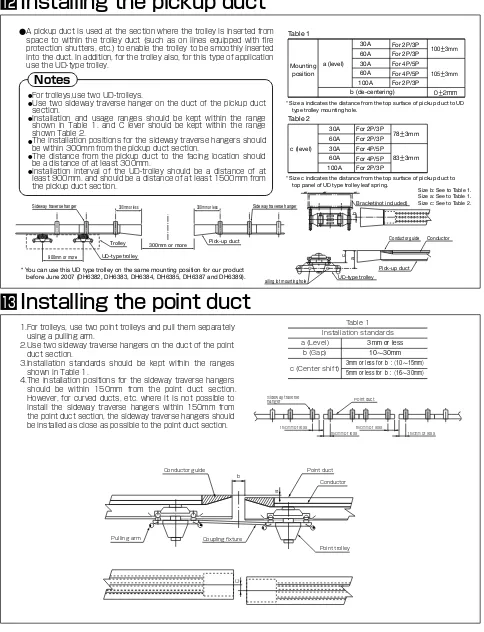
When the Fire Proof Shutter etc. are included on the Conveyor Line
The space can be installed in the Conveyor Line by using the pick-up duct and UD-type Trolley when the Fire Proof Shutter etc. are set up on the line of the conveyor pallet. Pick-up duct and UD-type trolley
A pick-up duct is used in areas such as the pallet entry section of an automated warehouse in order to facilitate smooth entry of the trolley from a section with no duct to the duct on the lines which partially consist of the Trolley Duct.
Along with the pickup ducts, use of UD-type trolleys (also tailored to this application) is recommended. For details regarding the pick-up ducts and UD-type trolleys, refer to the "Trolley Duct Product Guide" section (page 29-35).
12
Other applications
Cranes with multiple control linesAutomatic doors
Electric pallets
Arcade open/close systems
13
Trolley Duct Selection
Q&A
How can I determine the Trolley Duct
rated current from the load capacity?
The calculation of applicable rated current (applicable rating) is discussed below with examples classified into three loads: 1) a single load, 2) two or more loads, and 3) two or more loads, at least one of which is a motor.
1.A single load
2.Two or more loads
3.Two or more loads, at least one of which is a
motor.
(1) A motor (calculated at a working voltage of 200V).
If the rated current of the load is less than 50A:
Applicable rating is ≥ 1.25 times the rated current of the
load.
If the rated current of the load is more than 50A:
Applicable rating is ≥ 1.1 times the rated current of the
load.
(2) Other loads (except a welder): Applicable rating is
≥ 1.0 times the rated current of the load.
Example calculation
One 5.5kW motor is used (load current of 26A).
Total current requirements = 26A x 1.25 = 32.5A
(1) If the total rated current of the motor(s) is less than that of the other loads: Applicable rating is ≥ 1 times the total rated current of the whole load.
(2) When the total rated current of the motor(s) is more than that of other loads:
If the total rated current of the motor(s) is less than 50A: Applicable rating is ≥ (1.25 times the total rated current of the motor(s)) + (1 times the total rated current of other loads). If the total rated current of the motor(s) is more than 50A: Applicable rating is ≥ (1.1 times the total rated current of the motor(s)) + (1 times the total rated current of other loads).
Example calculation
(1) When the total rated current of the motor(s) is less
than that of other loads:
Three 0.75kW motors (load current of 4.7A) and three 1.7kW heaters (load current of 4.9A) are used.
Total current requirements = (4.7A x 3) + (4.9A x 3) = 28.8A
(2) When the total rated current of the motor(s) is more
than that of other loads:
Two 3.7kW motors (load current of 17A) and two 2kW/3 heaters (load current of 5.77A) are used.
Total current requirements = (17A x 2 x1.25) + (5.77A x 2) = 54.04A
Notes regarding calculation
(1) Determine the motor load current through calculations based on the nameplate, catalogue, indoor wiring regulations, and other pertinent regulations. For a general estimate, assume 4A per 1 kW at 200V.
(2) If the demand factor, power factor and other relevant values are known, use them to correct the calculation for the load current. Also, try to select the most cost-effective setup, taking such points as additional power installation into consideration. (3) For an overhead traveling crane, you may use the following equation for calculation.
Applicable Trolley Ducts according to electric hoist
crane rating (reference values)
(1) Motors
If the rated current of the load is less than 50A:
Applicable rating is ≥ 1.25 times the total rated current of
the motors.
If the rated current of the load is more than 50A:
Applicable rating is ≥ 1.1 times the total rated current of
the motors.
(2) Other loads (except a welder): Applicable rating is
≥ 1.0 times the total rated current of the whole load.
Example calculation
Fifteen 0.75 kW motors are used (load current of 4.7A).
Total current requirements = 4.7A x 15 x 1.1 = 77.55A
Trolley Duct Trolley
60A 40A
Trolley Duct Trolley
30A 20A
Trolley Duct Trolley
60A 40A
Trolley Duct Trolley
100A 40A
Total load current = Main hoisting motor current
2
Auxiliary hoisting motor current+Traveling motor current +Traversing motor current
0.5 ton 1 ton 2 ton 3 ton 5 ton 10 ton
Electrical hoist rating (200V)
Hoisting motor 6A 9A 15A 21A 30A 45A
Traveling motor 1.5A 1.5A 3.0A 4.5A 6.5A 9.0A
Trolley rating 20A 20A 20A 20A 20A 40A 40A 40A
Trolley Duct rating 30A 30A 30A 30A 60A 60A
Overhead traveling hoist crane
(200V)
Hoisting motor 6A 9A 15A 21A 30A 45A
Traveling motor 1.5A 1.5A 3.0A 4.5A 6.0A 9.0A Traversing motor 6.4A 6.4A 6.4A 16.0A 16.0A 22.0A
Trolley rating Traversing 20A 20A 40A 40A 80A 80A
Traveling 20A 20A 40A 80A 80A 80A
Trolley Duct rating Traversing 30A 30A 30A 60A 100A 100A
Traveling 30A 30A 60A 100A 100A 100A
Load current (I)
Trolley Duct installed length (L)
(A) indicates lengths when electricity is supplied from one end.
(B) indicates lengths when electricity is supplied from both ends or at the center. Voltage drop
(between lines)
14
Do voltage drops in the Trolley Duct
affect equipment in any way?
When the installation length is very long, voltage drops affect the motor and other loads positioned far from the power supply. If the voltage drop is too extreme (according to calculation of drop at the farthest point from the power supply when the total load current is applied), the rated current on the wiring should be raised by one step, or the power supply points should be changed or increased in number. The voltage drop in between the distribution board and the power supply points should also be taken into account.
Voltage drop calculation equation (three-phase,
three-wire)
E= 3 I Z L, where "I" is total rated load current (A), "Z" is impedance (Ω/m), and "L" is line length (m).
Voltage drop quick reference chart
This catalog includes a Trolley Duct voltage drop chart for a quick reference.
Reading the chart
For example, assume that a 60A Trolley Duct has been installed for 100m, power is fed into the end of the unit, and the total rated current of the load is 20A. Mark the 100m point on the horizontal axis, and the 20A point on the vertical axis. The point where the two lines intersect indicates the voltage drop to be about 2V.
60A Trolley Ducts
Rated current Resistance R(mΩ/m)
Resistance X (mΩ/m)
Impedance Z (mΩ/m)
30A 2.02 0.14 2.03
60A 0.57 0.14 0.59
100A 0.44 0.16 0.47
15
Trolley Duct Product Guide
Trolley Duct types and ratings
Trolley Duct is available in various types ranging from 30A to 400A. 600A to 3,000A Trolley Ducts are custom-made.
Note:
"Custom-made product" on the above table denotes that products are custom-designed and manufactured according to customer specifications. For lateral motion, be sure to use horizontal-traverse hangers (double hangers).
Rated
Cross-sectional view Compatible
trolleys Remarks
Standard type Outdoor type
30A 60A 300V
2P
2P type is custom-made.
20A 40A
Steel ducts are high-precision roll-formed products.
The surface is galvanized with chromate treatment. (The outdoor type has an additional clear lacquer layer.) 2P and 4P types have no center conductor. Horizontally and vertically curved ducts are also available.
3P 20A
40A
4P
4P type is custom-made.
20A 40A
5P 20A
40A
100A 600V 3P
2P type is custom-made. 2P type is custom-made.
40A 80A
Steel ducts are high-precision roll-formed products.
16
2P/3P, 30A/60A
Coupling plate set and conductor splice included. Hot-dipped galvanized steel
An opening is provided for trolley insertion and removal. A drop-out duct must be used for each line. For extended lines, a drop-out duct is used for every 20m.
2P/3P, 30A/60A Coupling plate set and
conductor splice included. Hot-dipped
galvanized steel
4P/5P, 30A/60A
Coupling plate set and conductor splice included.
Hot-dipped galvanized steel
4P/5P, 30A/60A
Coupling plate set and conductor splice included. Hot-dipped galvanized steel
Standard-type Trolley Ducts
30A 60A 300V
Unit :
30A
30A
60A 60A
For indoor use in an ordinary environment for electric hoists, cranes, etc. Dustproof type ducts (custom-made products) are designed for use in relatively poor
environments subject to excessive dust, such as cement, food, flour milling, livestock feed production facilities. Refer to the "Trolley Duct Installation" section (page 38 - 45) for product combinations and usage.
Straight-line ducts
Drop-out ducts (Photo shows a 3P, 30A type.) 2P type has no center conductor & conductor splice.
(Photo shows a 5P, 30A type.) 4P type has no center conductor & conductor splice.
(Photo shows a 3P, 30A type.) 2P type has no center conductor & conductor splice.
(Photo shows a 5P, 30A type.) 4P type has no center conductor & conductor splice.
Cat. No. Type Rating Standard length( ) Weight(kg)
DH6123
Cat. No. Type Rating Standard length( ) Weight(kg)
DH6161K DH6171K DH6181 DH6191
Cat. No. Type Rating Standard length( ) Weight(kg)
DH6261K2 DH6271K2 DH6281K2 DH6291K2
Cat. No. Type Rating Standard length( ) Weight(kg)
DH6223K2
Note: In addition to standard 1m, 2m, and 3m lengths, other lengths can also be made to order (200 minimum to 3m maximum).
Note: In addition to the standard 1m length, other lengths can also be made to order (500 minimum to 3m maximum).
Note: In addition to the standard 1m length, other lengths can also be made to order (500 minimum to 3m maximum).
Note: In addition to standard 1m, 2m, and 3m lengths, other lengths can also be made to order (200 minimum to 3m maximum).
Conductor cross-section
30A material: Brass 60A material: Copper
Conductor cross-section
17
Cat. No. Type Rating Weight(kg)
DH6172
Cat. No. Type Rating Weight(kg)
DH6192 Trolley rated current Minimum radius
(R) Available duct length
Trolley rated current Minimum radius
(R) Available duct length Standard-type Trolley Ducts
30A 60A 300V
3P, 30A/60A
Coupling plate set and conductor splice included. Hot-dipped galvanized steel
For 2P/3P, 30A/60A ducts
Coupling plate set and terminals included. Knockout diameter: 26.1, 32.5 Hot-dipped galvanized steel
For 4P/5P, 30A/60A ducts
Coupling plate set and terminals included. Knockout diameter: 32.5, 38.8
Hot-dipped galvanized steel 5P, 30A/60A
Coupling plate set and conductor splice included. Hot-dipped galvanized steel
Unit : Horizontally curved ducts
Feed-in boxes
(Photo shows a 3P, 30A type.)
(Photo shows a 5P, 60A type.)
Note: In addition to the listed radii and angles, other radii and angles are also available to order.
However, the minimum radius (R) and duct length ( ) are as shown according to the rated current of the trolley.
Note: In addition to the listed radii and angles, other radii and angles are also available to order.
However, the minimum radius (R) and duct length ( ) are as shown according to the rated current of the trolley.
30A
Note: 2P/4P type is custom-made.
Note: 2P/4P type is custom-made.
Terminal
18
Cat. No. Type Rating Weight(kg)
DH6112
Cat. No. Type Weight(kg)
DH6111
Cat. No. Type Weight(kg)
DH6113
Cat. No. Type Weight(kg)
DH6411
Cat. No. Type Weight(kg)
DH6413
Cat. No. Type Rating Weight(kg)
DH6114
Cat. No. Type Rating Weight(kg)
DH6173
Cat. No. Type Rating Weight(kg)
DH6193
Standard-type Trolley Ducts 30A 60A 300V
For 2P/3P, 30A/60A ducts
Solderless terminals (14 ) included. Knockout diameter: 26.1, 32.5 Hot-dipped galvanized steel
For 2P/3P, 30A/60A ducts Coupling plate set included. Hot-dipped galvanized steel
For 2P/3P, 30A/60A ducts
Used in locations where the duct moves or turns along with the device, such as a crane's lateral travel.
For 2P/3P, 30A/60A ducts
For 4P/5P, 30A/60A ducts
Crimp-on terminals (14 ) included. Knockout diameter: 32.5, 38.8 Hot-dipped galvanized steel
For 4P/5P, 30A/60A ducts Coupling plate set included. Hot-dipped galvanized steel
For 4P/5P, 30A/60A ducts
For 4P/5P, 30A/60A ducts Unit :
Center feed-in boxes
End caps
Hangers
Sideway-traverse hangers
Note: Photo shows a 3P type. 2P type is supplied with two terminals. Note: Photo shows a 5P type. 4P type is supplied with four terminals. Terminal
19
Standard-type Trolley Ducts 30A 60A 300V
2P/3P, 20A trolley for 30A/60A ducts
With this trolley type, cables are connected to the side of the trolleys.
2P/3P, 20A trolley for 30A/60A ducts
Used when smooth movement is required, such as cutting machines and bolt spreaders in sewing factories.
2P/3P, 5A trolley for 30A/60A ducts
4P/5P, 20A trolley for 30A/60A ducts 5P, 40A trolley for 30A/60A ducts
4P/5P, 20A trolley for 30A/60A ducts
2P/3P, 40A trolley for 30A/60A ducts
3P, 40A trolley for 30A/60A ducts Standard trolleys
Side outlet cable trolleys
Roller type trolleys
3.5 pressure terminals included.
3.5 pressure terminals included. 3.5 pressure terminals included. 8 pressure terminals included. 8 pressure terminals included. 3.5 pressure
terminals included.
8 pressure terminals included.
Cat. No. Type Product name Weight(kg)
DH6165
DH6175
Cat. No. Type Product name Weight(kg)
DH6362
DH6363
Cat. No. Type Product name Weight(kg)
DH6364
DH6365
Cat. No. Type Product name Weight(kg)
DH6367
Cat. No. Type Product name Weight(kg)
DH6075
DH6076 Cat. No. Type Product name Weight(kg)
DH6185
DH6195
DH6296
Cat. No. Type Product name Weight(kg)
DH6266
DH6276
Note: Photo shows 3P type. 2P type has no center collector.
Note: Photo shows 3P type. Note: Photo shows 5P type.
Note: 2P type is custom-made.
Note: Photo shows 3P trolley. Roller type trolleys are not usable with curved ducts. Note 1: Photo shows 5P type. 4P type has no center collector.
Note 2: 4P, 40A trolley is custom-made.
20 Standard-type Trolley Ducts 30A 60A 300V
Used with a pull-type trolley.
Used for cleaning the conductor surface. It should regularly be run over the conductor surface.
Trolley collectors make direct contact with conductors for collecting power. Worn-out collectors should be replaced.
For coupling two trolleys.
A set consists of coupling plates and conductor splice. 2P/3P/4P/5P, 60A
Hot-dipped galvanized steel Unit :
Trolley-pulling brackets
Conductor cleaners
Trolley collectors
Coupling fixture A
Accessory sets for connections(Custom-made products) Conductor splice
Conductor cleaner pads
Cat. No. Product name Compatible trolleys
DH6117 DH6119
Cat. No. Product name Compatible trolleys
DH6166 DH6167
Cat. No. Product description Compatible ducts
DH6202 DH6203
Cat. No. Compatible trolleys
DH6108
Compatible ducts
Cat. No. Compatible ducts
DH6116
Cat. No. Product name
DH6000
Note: Custom-made products. Note: When using the cleaner, be sure to switch off power to prevent possible
short circuits.
Note1: One set contains the number of collectors needed for one trolley (two for 2P type, three for 3P type, etc).
Note2: Collectors for dustproof type trolleys are made to order.
Accessories and Maintenance Parts for Standard and Outdoor Type Trolley Ducts
20A collector 5A collector
DH6117 DH6119
Material: Copper
Terminal
Terminal
21
3P, 100A
Coupling plate set and conductor splice included. Hot-dipped galvanized steel
3P, 100A
Coupling plate set and conductor splice included. Hot-dipped galvanized steel
For 3P, 100A ducts
Crimp-on terminals (38 ) included. Knockout diameter: 32.5, 38.8 Hot-dipped galvanized steel
3P, 100A
Coupling plate set and conductor splice included. Hot-dipped galvanized steel
For 3P, 100A ducts
Coupling plate set and terminals included. Knockout diameter: 32.5, 38.8 Hot-dipped galvanized steel
For 3P, 100A ducts Coupling plate set included. Hot-dipped galvanized steel
Unit : Straight-line ducts
Horizontally curved ducts
Center feed-in box
Drop-out duct
Feed-in box
End cap 2P type has no center
conductor or conductor splice.
Standard-type Trolley Ducts
100A 600V
Cat. No. Type Rating Standard length( ) Weight(kg)
DH6433K2 DH6432K2 DH6431K2
Cat. No. Type Rating R Weight(kg)
DH6436K2 DH6438K2
Cat. No. Type Rating Standard length( ) Weight(kg)
DH6471K2
Cat. No. Type Rating Weight(kg)
DH6472
Cat. No. Type Rating Weight(kg)
DH6473
Cat. No. Type Rating Weight(kg)
DH6412 Note: In addition to standard 1m, 2m, and 3m lengths, other lengths can also be
made to order (200 minimum to 3m maximum). 2P type is custom-made.
Note: In addition to the listed radii and angles, other radii and angles are also available to order.
However, the minimum radiuses are 1,000 and 2,500 for 40A and 80A trolleys, respectively, and duct lengths are 500 minimum and 1,800 maximum.
Note: In addition to the standard 1m length, other lengths can also be made to order (500 minimum to 3m maximum). 2P type is custom-made.
22 Standard-type Trolley Ducts 100A 600V
For 3P, 100A ducts
3P, 40A trolley for 100A ducts 3P, 80A trolley for 100A ducts
Used with a pull-type trolley.
Used in locations where the duct moves or turns along with the device, such as a crane's lateral travel.
For 3P, 100A ducts
With this trolley type, cables are connected to the side of the trolleys. 3P, 40A trolley for 100A ducts
For coupling two trolleys. Unit :
Hanger
Standard trolleys
Trolley-pulling brackets
Sideway-traverse hanger
Side outlet cable trolley
Coupling fixtures 8 pressure terminals included.
DH6117 DH6119
Coupling fixture A Coupling fixture B 8 pressure terminals included.
Without pressure terminals
Cat. No. Type Product name Weight(kg)
DH6476 DH6477
Cat. No. Product name Compatible trolleys A B
DH6117 DH6119 DH6417
Cat. No. Product name Compatible trolleys
DH6108 DH6109
Cat. No. Type Product name Weight(kg)
DH6369
Note: 2P type is custom-made.
Note: 2P type is custom-made.
Cat. No. Type Weight(kg)
DH6411
Cat. No. Type Weight(kg)
DH6413
23
Standard-type Trolley Ducts 100A 600V
Used for cleaning the conductor surface. It should regularly be run over the conductor surface.
Trolley collectors make direct contact with conductors for collecting power. Worn-out collectors should be replaced.
A set consists of a coupling plate and conductor splice.3P, 100A Hot-dipped galvanized steel
Conductor cleaner
Trolley collectors
Accessory sets for connections(Custom-made products)
Conductor splice
Conductor cleaner pads
40A collector
Note: When using the cleaner, be sure to switch off power to prevent possible short circuits.
Note: One set contains the number of collectors needed for one trolley (two for 2P type and three for 3P type).
Cat. No. Product name Compatible ducts
DH6167
Cat. No. Compatible ducts
DH6116
Rating
Cat. No. Product description Compatible ducts
DH6203
Cat. No. Product name
DH6104 DH6105 DH6106 DH6107
24
3P, 30A/60A
Coupling plate set, conductor splice and cover included. Hot-dipped galvanized steel
An opening is provided for trolley insertion and removal. A drop-out duct must be used for each line. For extended lines, a drop-out duct is used for every 20m.
3P, 30A/60A
Coupling plate set, conductor splice and cover included. Hot-dipped galvanized steel 5P, 30A/60A
Coupling plate set, conductor splice and cover included. Hot-dipped galvanized steel
5P, 30A/60A
Coupling plate set, conductor splice and cover included. Hot-dipped galvanized steel
Unit :
Straight-line ducts
Drop-out ducts
(Photo shows 3P, 30A type.)
(Photo shows 5P, 30A type.)
(Photo shows 3P, 30A type.)
(Photo shows 5P, 30A type.)
Outdoor-type Trolley Ducts
30A 60A 300V
The rain-proof construction makes these Trolley Ducts suitable for outdoor installations. Note: Avoid installation in coastal areas.
30A
30A 60A
60A
Cat. No. Type Rating Standard length( ) Weight(kg)
DH6533 DH6553
Cat. No. Type Rating Standard length( ) Weight(kg)
DH6571K DH6591
Cat. No. Type Rating Standard length( ) Weight(kg)
DH6633K2 DH6653K2
Cat. No. Type Rating Standard length( ) Weight(kg)
DH6671K2 DH6691K2
Note: In addition to the standard 3m length, other lengths can also be made to order (500 minimum to 3m maximum). 2P/4P type is custom-made.
Note: In addition to the standard 1m length, other lengths can also be made to order (800 minimum).
2P/4P type is custom-made.
Note: In addition to the standard 3m length, other lengths can also be made to order (500 minimum to 3m maximum). 2P/4P type is custom-made.
Note: In addition to the standard 1m length, other lengths can also be made to order (800 minimum).
2P/4P type is custom-made.
Cover
Outdoor-type Trolley Ducts 30A 60A 300V
3P/5P, 30A
Coupling plate set, conductor splice and cover included. Hot-dipped galvanized steel
3P, 30A/60A
Coupling plate set, terminals and cover included. Knockout diameter: 26.1, 32.5
Hot-dipped galvanized steel
3P, 30A/60A Cover included. Crimp-on terminals 14 and cover included.
Knockout diameter: 26.1, 32.5 Hot-dipped galvanized steel
5P, 30A/60A
Coupling plate set, terminals and cover included. Knockout diameter: 32.5, 38.8
Hot-dipped galvanized steel
5P, 30A/60A Cover included. Crimp-on terminals 14 and cover included.
Knockout diameter: 32.5, 38.8 Hot-dipped galvanized steel
3P/5P, 60A
Coupling plate set, conductor splice and cover included. Hot-dipped galvanized steel
Unit : Horizontally curved ducts(Custom-made products)
Feed-in boxes
Center feed-in boxes
Cover
Cover
Cover
Cover
30A 60A
Type Rating Minimum R Available duct length Type Rating Minimum R Available duct length
Note: Custom-made products. Note: Custom-made products.
Cat. No. Type Rating Weight(kg)
DH6572
Cat. No. Type Rating Weight(kg)
DH6573
Cat. No. Type Rating Weight(kg)
DH6592
Cat. No. Type Rating Weight(kg)
26 Outdoor-type Trolley Ducts 30A 60A 300V
3P, 30A/60A Cover included.
Hot-dipped galvanized steel
For 2P/3P, 30A/60A ducts
Used in locations where the duct moves or turns along with the device, such as a crane's lateral travel.
For 2P/3P, 30A/60A ducts
5P, 30A/60A Cover included.
Hot-dipped galvanized steel
For 4P/5P, 30A/60A ducts
For 4P/5P, 30A/60A ducts Unit :
Cat. No. Type Rating Weight(kg)
DH6512
Cat. No. Type Rating Weight(kg)
DH6514
Cat. No. Type Weight(kg)
DH6111
Cat. No. Type Weight(kg)
DH6113
Cat. No. Type Weight(kg)
DH6411
Cat. No. Type Weight(kg)
DH6413
Cat. No. Type Product name
Compatible ducts
DH6275
Cat. No. Type Product name
Compatible ducts
DH6295
Cat. No. Type Product name
Compatible ducts
DH6576
Note: 2P type is custom-made. Note: 4P type is custom-made. Note: 2P type is custom-made.
Cover
Coupling plate set, conductor splice and cover included. Hot-dipped galvanized steel
3P, 100A
Coupling plate set, conductor splice and cover included. Hot-dipped galvanized steel
3P, 100A Cover included.
Solderless terminals (38 ) and cover included. Knockout diameter: 32.5, 38.8
Hot-dipped galvanized steel
3P, 100A
Coupling plate set, conductor splice and cover included. Hot-dipped galvanized steel
3P, 100A
Coupling plate set, terminals and cover included. Knockout diameter: 32.5, 38.8
Hot-dipped galvanized steel
3P, 100A Cover included.
Hot-dipped galvanized steel
Unit : Straight-line duct
Horizontally curved duct(Custom-made products)
Center feed-in box
Drop-out duct
Feed-in box
End cap
Cover
Cover Cover
Outdoor-type Trolley Ducts
100A 600V The rain-proof construction makes these Trolley Ducts suitable for outdoor installations.
Cat. No. Type Rating Standard length( ) Weight(kg)
DH6933K2
Cat. No. Type Rating Standard length( ) Weight(kg)
DH6943K2 Note: In addition to the standard 3m length, other lengths can also be made to order
(500 minimum to 3m maximum). 2P type is custom-made.
Note: In addition to the standard 1m length, other lengths can also be made to order (800 minimum). 2P type is custom-made.
Cat. No. Type Rating Weight(kg)
DH6953
Cat. No. Type Rating Weight(kg)
DH6515
Cat. No. Type Rating Weight(kg)
DH6963
Type Rating Minimum R Available duct length
28 Outdoor-type Trolley Ducts 100A 600V
For 3P, 100A ducts Used in locations where the duct moves or turns along with the
device, such as a crane's lateral travel.For 3P, 100A ducts Unit :
Hanger
Outdoor-type trolley
Sideway-traverse hanger
Cat. No. Type Weight(kg)
DH6411
Cat. No. Type Weight(kg)
DH6413
Cat. No. Type Product name Compatible ducts
DH6676
Cat. No. Type Product name Compatible ducts
DH6696
Note: 2P type is custom-made. Note: 2P type is custom-made.
Guide
Guide Pick-up
29
Straight-line ducts without conductors.2P/3P/4P/5P, 30A/60A 3P, 100A
Coupling plate set included. Hot-dipped galvanized steel
Straight-line ducts without conductors, used at switching points such as turntables and traversers.
2P/3P/4P/5P, 30A/60A 3P, 100A
Coupling plate set included. Hot-dipped galvanized steel
Straight-line ducts with conductors for use at switching points such as turntables and traversers.
2P/3P/4P/5P, 30A/60A Coupling plate set included. Hot-dipped
galvanized steel
Straight-line ducts without conductors, which are provided with an opening for trolley insertion and removal.
2P/3P/4P/5P, 30A/60A 3P, 100A
Coupling plate set included. Hot-dipped galvanized steel
Straight-line ducts without conductors, used when the Trolley Duct length needs adjustment to match the stretching of the chain conveyor in an endless line.
Standard length: 1000 / maximum adjustable length: 550
2P/3P/4P/5P, 30A/60A 3P, 100A
Coupling plate set included. Hot-dipped galvanized steel
Ducts for use at either end in lines which partially consist of a Trolley Duct.
2P/3P/4P/5P, 30A/60A
Wireless ducts(Custom-made products)
Wireless point ducts(Custom-made products)
Point ducts (with conductors)(Custom-made products)
Wireless drop-out ducts(Custom-made products)
Wireless take-up ducts(Custom-made products)
Pick-up ducts (with conductors)(Custom-made products)
Trolley Ducts for Special Applications
30A 60A 300V (custom-made products)
Type Compatible ducts Standard length( ) Type Compatible ducts Standard length( )
Type Compatible ducts Standard length( )
Type Rating Standard length( ) Type Rating Standard length( )
Type Compatible ducts Standard length( )
Note: Custom-made products.
Note: Custom-made products.
Note: Custom-made products.
Note: Custom-made products.
Note: Custom-made products.
Conductor guide
Solderless terminal 14
Trolley travel direction A-A cross-section
Limit switch
Idle 49.5 In use 38.8
Center feed-in box
No-conductor section dimensions -type
cutting
A-A cross-section
Limit switch
Idle In use Center feed-in box Solderless
terminal 14
Trolley travel direction No-conductor section dimensions
-type cutting
With conductor
Without conductor
30 Trolley Ducts for Special Applications 30A 60A 300V
These ducts are provided with a guide to help the trolley move smoothly between duct sections with and without conductors on endless aging or product inspection lines, where Trolley Ducts without conductors are partially used.Coupling plate set and conductor splice included.
Hot-dipped galvanized steel
Ducts for use in separating circuits. Two types are available: a power-circuit use type with a function to extinguish arcs created by load current, and a signal-circuit type without arc-extinguishing function.
Coupling plate set and conductor splice included. Hot-dipped galvanized steel
Unit :
Ducts with conductor guide(Custom-made products)
Circuit-separating ducts(Custom-made products)
Note 1: Dimensions (L) and ( ) are determined after consulting customers. See page 37 for -type cutting.
Note 1: Dimensions (L) and ( ) are determined after consulting customers. See page 37 for -type cutting.
30A
60A
Type Rating Weight (kg)
Type Rating Weight (kg)
3P, 30A/60A ducts
5P, 30A/60A ducts
For signal circuits ( -type cutting) 2P type has no center conductor.
For power circuits ( -type cutting)
For signal circuits ( -type cutting) 4P type has no center conductor.
A-A’ cross-section
Downward-facing
Upward-facing
31
Trolley Ducts for Special Applications 30A 60A 300V
Vertically curved ducts are available in two types: downward-facing and upward-facing.Coupling plate set and conductor splice included.
Hot-dipped galvanized steel
Used with an automatic control circuit for conveyor lines, these trolleys include a mechanism for operating the microswitches which are built into the ducts. Use together with a circuit-separating duct.
Used where line switching is performed on circuits having turntables or traversers. Use with a point duct for line switching (see page 29).
3P, 20A trolley (for 30A/60A ducts)
3P, 40A trolley for 30A/60A ducts
4P/5P, 20A trolley for 30A/60A ducts 5P, 20A trolley
(for 30A/60A ducts)
3P, 40A trolley (for 60A ducts)
Unit :
Vertically curved ducts(Custom-made products)
Micro-rod attached trolleys
Point-use trolleys
Note: 2P and 4P types have no center conductor & conductor splice.
30A
30A
Type Rating Minimum radius R Duct length
With conductors Without conductors Minimum Maximum
Type Rating Minimum radius R Duct length
With conductors Without conductors Minimum Maximum
3.5 pressure terminals included. 3.5 pressure terminals included. 8 pressure terminals included.
Cat. No. Type Product name Weight(kg)
DH6373
Cat. No. Type Product name Weight(kg)
DH6375
Cat. No. Type Product name Weight(kg)
DH6377
Note: 2P type is custom-made. Note: 4P type is custom-made. Note: 2P type is custom-made.
8 pressure terminals included. 3.5 pressure terminals included.
Cat. No. Type Product name Weight(kg)
DH6397
Cat. No. Type Product name Weight(kg)
DH6394
DH6395 Note: 2P type is custom-made.
32 Trolley Ducts for Special Applications 30A 60A 300V
Used on circuits which partially employ a Trolley Duct. A mechanism that allows the trolley to move smoothly from a non-duct section to a duct section is included. Use with a pick-up duct (see page 29).
For use with the custom-made dustproof Trolley Ducts.3P/5P, 20A trolley (for 30A/60A ducts) 3P, 40A trolley (for 60A ducts)
2P/3P, 20A trolley (for 30A/60A ducts)
3P, 40A trolley for 60A ducts
4P/5P, 20A trolley for 30A/60A ducts Unit :
UD-type trolleys
Dustproof trolleys(Custom-made products)
3.5 pressure terminals included. 8 pressure terminals included. 3.5 pressure terminals included.
Cat. No. Type Product name Weight(kg)
DH6382K
DH6383K
Cat. No. Type Product name Weight(kg)
DH6387K
Cat. No. Type Product name Weight(kg)
DH6384K
DH6385K
Note: Photo shows 3P, 20A trolley. 2P type has no center collector.
Note: 2P type is custom-made.
Note: Photo shows 5P, 20A trolley. 4P type has no center collector.
Type Product name Weight(kg)
Note: Custom-made products.
Pick-up Guide
Guide
33
Straight-line ducts without conductors.3P, 100A Coupling plate set included. Hot-dipped galvanized steel
A straight-line duct without conductor, used at switching points such as turntables and traversers.
3P, 100A
Coupling plate set included. Hot-dipped galvanized steel
A straight-line duct with conductor for use at switching points such as turntables and traversers.
3P, 100A
Coupling plate set included. Hot-dipped galvanized steel
A straight-line duct without conductor, which is provided with an opening for trolley insertion and removal.
3P, 100A
Coupling plate set included. Hot-dipped galvanized steel
A straight-line duct without conductor, used when the Trolley Duct length needs adjustment to match the stretching of the chain conveyor in an endless line.
Standard length: 1000 ; maximum adjustable length: 550 3P, 100A
Coupling plate set included. Hot-dipped galvanized steel
A duct for use at either end in lines which partially consist of a Trolley Duct.
3P, 100A
Coupling plate set included. Hot-dipped galvanized steel
Unit :
Wireless ducts(Custom-made products)
Wireless point duct(Custom-made products)
Point duct (with conductor)(Custom-made products)
Wireless drop-out duct(Custom-made products)
Wireless take-up duct(Custom-made products)
Pick-up duct(with conductor)(Custom-made products)
Trolley Ducts for Special Applications
100A 600V (custom-made products)
Type Compatible ducts Standard length( ) Type Compatible ducts Standard length( )
Type Compatible ducts Standard length( )
Type Rating Standard length( ) Type Rating Standard length( )
Type Compatible ducts Standard length( )
Note: Custom-made products.
Note: Custom-made products.
Note: Custom-made products.
Note: Custom-made products.
Conductor guide
A-A’ cross-section
2P type has no center conductor & conductor splice.
No-conductor section dimensions
Crimp-on termina
dle n use
For signal circuits ( -type cutting)
For power circuits ( -type cutting)
Trolley travel direction
-type cutting
With conductor
Without conductor
34 Trolley Ducts for Special Applications 100A 600V
This duct is provided with a guide to help the trolley move smoothly between duct sections with and without conductors on endless aging or product inspection lines, where Trolley Ducts without conductors are partially used.Coupling plate set and conductor splice included.
Hot-dipped galvanized steel
Ducts for use in separating circuits. Two types are available: a power-circuit use type with a function to extinguish arcs created by load current, and a signal-circuit type without arc-extinguishing function.
Coupling plate set and conductor splice included. Hot-dipped galvanized steel
Unit :
Duct with conductor guide(Custom-made products)
Circuit-separating ducts(Custom-made products)
Note 1: Dimensions (L) and ( ) are determined after consulting customers. 2:See page 37 for -type cutting.
3:Custom-made products.
Type Rating Standard length( ) Weight(kg)
Downward-facing Upward-facing
Equation A-A’ cross-section
35
Trolley Ducts for Special Applications 100A 600V
The vertically curved duct is available in two types: downward-facing and upward-facing. Coupling plate set and conductor splice
included.
Hot-dipped galvanized steel
Used with an automatic control circuit for conveyor lines, this trolley includes a mechanism for operating the microswitches which are built into the ducts. Use together with a circuit-separating duct.
3P, 40A trolley for 100A ducts
Used where line switching is performed on circuits having turntables or traversers. Use with a point duct for line switching (see page 33).
For use with the custom-made dustproof Trolley Ducts.
Used on circuits which partially employ a Trolley Duct. A mechanism that allows the trolley to move smoothly from a non-duct section to a duct section is included. Use with a pick-up duct (see page 33).
3P, 40A trolley for 100A ducts
Unit :
Vertically curved duct(Custom-made products)
Micro-rod attached trolley
Point-use trolleys Dustproof trolley(Custom-made products)
UD-type trolley
Type Rating Minimum radius R Duct length
With conductors Without conductors Minimum Maximum
Note: 2P type has no center conductor.
Note: Use a 40A trolley. 80A trolley cannot be used.
8 pressure terminals included. 8 pressure terminals included.
Cat. No. Type Product name Weight(kg)
DH6379
Cat. No. Type Product name Weight(kg)
DH6389K
Note: 2P type is custom-made. Note: 2P type is custom-made.
3P, 40A trolley for 100A ducts 3P, 80A trolley for 100A ducts 3P, 40A trolley for 100A ducts
8 pressure terminals included. Without pressure terminals.
Cat. No. Type Product name Weight(kg)
DH6399
Cat. No. Type Product name Weight(kg)
DH6393
Type Product name Weight(kg)
Trolley-pulling bracket
Point duct
Conductor
Point-use trolley Conductor guide
CTB: Center feed-in box
Trolley Duct (power circuit)
I-beam or conveyor
Circuit dead section
Trolley Duct (control circuit) (Insulated section)
Conductor
36
1.Connect two point-use trolleys using a coupling fixture. (For trolley connecting procedures, see page 43.)
2.Use a sideway-traverse hanger for the point duct (see page 45).
3.Allowable installation errors (during operation) are listed below:
Automated conveyor lines require a control circuit to prevent conveyed items colliding or for automatic elevation of a hoist, in addition to the Trolley Duct for feeding power to the lines. A circuit-separating duct (including a section with no conductors) is used for the control circuit.
Consult Matsushita Electric Works for conductor cutting methods and their applications.
Unit :
Detailed information regarding switching points (traversers and turntables)
Providing an automatic control circuit Standard point dimensions
Allowable installation error
R Max. X
60A 100A
Name Conductor cutting point Symbol
Rating Minimum radius R
1 Voltage (V) Point-use trolley Max. Max.
Note: Dimensions for X should be determined by checking the spacing between the hoist/I-beam and the duct. Standards for cutting points
(Insulated section)
Conductors Conductor
g
g g
Conductors
g g
Conductors
Knockout side
Microswitch Trolley
Duct
Trolley travel direction
Conductor guide
37
Unit : Conductor cutting methods
Circuit-separating ducts
-type cutting without neutral sections -type cutting with one neutral section -type cutting with two neutral sections
CTB
mounting direction Front Back Front/back
MS: microswitch Mg: Magnetic switch
Note 1: Magnetic switch connection is provided separately. 2: A microswitch is included with a duct.
3: An 80A trolley cannot be used.
CTB: Center feed-in box, MS: Microswitch, G: Conductor guide
39
40
41
42
43
Mounting
30A For 2P/3P For 2P/3P
* Size a indicates the distance from the top surface of pickup duct to UD type trolley mounting hole.
Sideway traverse hanger Sideway traverse hanger
UD-type trolley
Trolley 300mm or more Pick-up duct
900mm or more
300mm or less 300mm or less
c (level) 60A 100A
30A 60A
30A For 2P/3P For 2P/3P
* Size c indicates the distance from the top surface of pickup duct to top panel of UD type trolley leaf spring.
* You can use this UD type trolley on the same mounting position for our product before June 2007 (DH6382, DH6383, DH6384, DH6385, DH6387 and DH6389).
b
Bracket(not included)
c
UD-type trolley ailing lot mounting hole
Conductor guide Conductor
Collector
Replacement line (Wear limit line)
Terminal block
Lead wire fixing
screw Terminal block
fixing screw
Collector
Protrusion of insulator
Collector (red)
Check that each spring is fully fit over the protrusions of the insulator.
Collector cover mounting screws
Collector cover
Attach collector cover from 2-collector row side.
Terminal block
Groove Lead wire fixing
screw
Check that all springs are firmly fit over the corresponding projections.
Box cover
Box cover mounting screw Collector Collector cover mounting screws
Collector cover
Box cover
Box cover mounting screw
Caution
47
Replacement of collectors
Removing collectors
Installing collectors
Collector replacement timing
1.Install the collectors in the insulator in the positions corresponding to the painted colors. (Example: 5 collectors)
2.Attach the collector cover. (Proper tightening torque: 1.0 to 1.5N·m) Note: Be careful not to pinch the silicon tubes.
3.Match the colors of the silicon tubes from the collectors to the corresponding colors of the terminal block and fasten the lead wires in place by tightening the lead wire fixing screws. After that, push the lead wires into the grooves, and fasten the terminal block with the terminal block fixing screws. Note: Be careful not to pinch the silicon tubes. (Proper tightening torque: 1.0 to 1.5N·m)
4.Replace the box cover and tighten the box cover mounting screw.
(Proper tightening torque: 1.0 to 1.5N·m) Collectors have an engraved replacement line. Replace
collectors when they have been worn down to the replacement line. In addition, if there is a possibility that the collector will be worn down to the replacement line before the next maintenance cycle, the collector should be replaced early.
1.Unscrew the box cover mounting screw and remove the box cover.
2.Unscrew the lead wire fixing screws and terminal block fixing screws inside the box and remove the terminal block.
3.Unscrew the collector cover mounting screws, remove the collector cover, and remove the collectors.
Install the center collector (red) of the 3-collector row first in the insulator side.
Check that the springs of the collectors are fully fit over the protrusions of the insulator.
Install the collectors (yellow, black) on both sides of the 3-collector row.
Attach the collector cover from the 2-collector row side.
Install the collectors (white, green) in the 2-collector row side.
Look through the gap between the insulator and the collector cover and check again that all springs are fully fit over the projections.
If a spring has come out of the projection, use tweezers to put the spring back in its proper position.
When passing the collector lead wires through the insulator, be sure that the wires do not cross over each other. In addition, pass the lead wires through in the order of the terminal block colors. Failure to do so may place strain on the collectors, resulting in disconnection, arcing, uneven wear, etc.