DEVELOPMENT OF AN EXTREMELY ROBUST AUTOMOTIVE SUSPENSION SYSTEM USING INTELLIGENT ACTIVE FORCE
CONTROL
(PEMBANGUNAN SISTEM SUSPENSI KENDERAAN LASAK MENGGUNAKAN KAWALAN DAYA AKTIF PINTAR)
MUSA MAILAH
HISHAMUDDIN JAMALUDDIN MOHD ZARHAMDY MOHD ZAIN
GIGIH PRIYANDOKO
MOHAMAD AKMAL BAHRAIN ABDUL RAHIM
RESEARCH VOTE NO: 74221
RESEARCH MANAGEMENT CENTRE UNIVERSITI TEKNOLOGI MALAYSIA
UNIVERSITI TEKNOLOGI MALAYSIA
UTM/RMC/F/0024 (1998)
BORANG PENGESAHAN LAPORAN AKHIR PENYELIDIKAN
TAJUK PROJEK : DEVELOPMENT OF AN EXTREMELY ROBUST AUTOMOTIVE
SUSPENSION SYSTEM USING INTELLIGENT ACTIVE FORCE CONTROL
Saya _________________________MUSA BIN MAILAH_ ___________________________ (HURUF BESAR)
Mengaku membenarkan Laporan Akhir Penyelidikan ini disimpan di Perpustakaan Universiti Teknologi Malaysia dengan syarat-syarat kegunaan seperti berikut :
1. Laporan Akhir Penyelidikan ini adalah hakmilik Universiti Teknologi Malaysia.
2. Perpustakaan Universiti Teknologi Malaysia dibenarkan membuat salinan untuk tujuan rujukan sahaja.
3. Perpustakaan dibenarkan membuat penjualan salinan Laporan Akhir Penyelidikan ini bagi kategori TIDAK TERHAD.
4. * Sila tandakan ( / )
SULIT (Mengandungi maklumat yang berdarjah keselamatan atau
Kepentingan Malaysia seperti yang termaktub di dalam
AKTA RAHSIA RASMI 1972).
TERHAD (Mengandungi maklumat TERHAD yang telah ditentukan oleh Organisasi/badan di mana penyelidikan dijalankan).
TIDAK
TERHAD
TANDATANGAN KETUA PENYELIDIK
PROFESOR MADYA DR. MUSA MAILAH
Nama & Cop Ketua Penyelidik
Tarikh : 10 APRIL 2007
/
CATATAN : * Jika Laporan Akhir Penyelidikan ini SULIT atau TERHAD, sila lampirkan surat daripada pihak
berkuasa/organisasi berkenaan dengan menyatakan sekali sebab dan tempoh laporan ini perlu dikelaskan sebagai SULIT dan TERHAD. Lampiran 20
DEDICATIONS
To all
Intelligent Active Force Control Research Group
(IAFCRG) members – a
big thank you
for all your
iv
ACKNOWLEDGEMENTS
We would like to express our sincere gratitude and appreciation to the Ministry of Science Technology and Innovation (MOSTI), Malaysia, for providing the project research grant (Project No.: 03-02-06-0123EA001) and the Universiti Teknologi Malaysia (UTM) for their full support in terms of accommodating the research infrastructures and facilities. Special thanks go to Abdul Rahim Mohamad, Ahmad Faisal and Ahmad Shahrizam from the Systems & Control Laboratory for their meaningful contribution in assisting some of the works related to this project. Last but not least to everyone who has in one way or another contributed to the success of this project.
ABSTRACT
This report describes both theoretical and experimental studies of a quarter-car
vehicle suspension system that incorporates a number of control schemes in which a
number of responses or characteristics were rigorously investigated. Particular focus is
on the application of a very practical robust control scheme known as active force
control (AFC) that is expected to render any forms of disturbances on the system to be
effectively compensated. These disturbances are mostly in the form of various modelled
road profiles (terrains) that the unsprung mass (tyre or wheel) comes in direct contact
with and which in turn are transmitted to the sprung mass (body) of the system causing
undesirable vibration or shaking that may cause discomfort to the ‘passenger’. Thus, it is
the main aim of this study to come up with solution/s that can minimise this discomfort
condition (thereby improved the riding comfort) in such a way that the body of the
vehicle shall remain almost indifferent to the introduced disturbances. In other words,
the sprung mass (body) of the vehicle is extremely robust to the vibration or other
external forces. A direct measure would be the significant reduction in the body
acceleration and displacement. Intelligent techniques employing neural network (NN),
adaptive fuzzy logic (AFCL) and their hybrids were value-added contributions that were
deliberately and primarily introduced into the AFC schemes to approximate the virtual
estimated mass of the system that is vital to trigger the AFC mechanism.
Indeed,simulation results have shown the extreme robust nature of the AFC-based schemes embedded with a number of intelligent methods in countering and nullifying the induced vibration effects and other adverse conditions. The simulation results were then consequently validated by experiments conducted on a working prototype which is mechatronically designed and developed in a laboratory. The body acceleration and displacement of the system were
considerably reduced to more than 70% compared to a passive control system and about 50% to a closed-loop proportional-integral-derivative (PID) control, thereby exhibiting the robust performance of the proposed AFC-based methods.
vi
ABSTRAK
Laporan ini menerangkan secara teori dan juga ujikaji terhadap suatu sistem suspensi kenderaan suku-kereta yang memuatkan beberapa skema kawalan di mana sambutan atau ciri sistem dikaji secara mendalam. Tumpuan lebih menjurus kepada aplikasi suatu teknik praktikal yang lasak serta dikenali sebagai kawalan daya aktif (AFC) yang boleh mengakibatkan sebarang gangguan terhadap sistem dipampas atau dihindarkan dengan amat baik. Gangguan ini
sebahagian besarnya berpunca dari keadaan permukaan jalan di mana ia bersentuhan dengan jisim tak berspring (tayar atau roda) menyebabkan berlakunya getaran tak diingini pada jisim berspring (badan) kenderaan dan seterusnya boleh mendatangkan kesan tidak selesa terhadap pengguna. Maka, adalah menjadi tujuan utama projek ini dirangkakan untuk mencari jalan penyelesaian terhadap keadaan ketidakselesaan (dengan demikian, meningkatkan keselesaan pemanduan) begitu rupa sehingga badan sistem kenderaan masih tidak terkesan dengan sebarang gangguan yang dikenakan pada sistem. Dengan perkataan lain, badan kenderaan adalah sangat lasak terhadap sebarang kesan getaran atau tindakan daya luaran. Suatu ukuran yang
menunjukkan keberkesanan ini ialah kadar penurunan pecutan dan anjakan badan. Beberapa teknik pintar menggunakan rangkaian neural (NN), logik kabur boleh suai (AFL) serta hibridnya merupakan sumbangan yang dapat menambah-nilai kajian di mana ia digunakan terutama sekali untuk mendapatkan nilai jisim maya anggaran yang diperlukan untuk menjalankan mekanisme AFC. Hasil kajian simulasi menunjukkan ciri amat lasak skema berasaskan AFC yang
dimuatkan dengan teknik kawalan pintar di mana ia dapat mengatasi dan mengurangkan kesan getaran dan beberapa keadaaan yang ‘memudaratkan’. Hasil kajian simulasi juga dapat ditentusahkan melalui ujikaji sebenar terhadap prototaip yang telah direka bentuk dan dibangunkan menggunakan pendekatan mekatronik di dalam makmal. Pecutan dan anjakan badan yang diperoleh menunjukkan pengurangan sehingga sebanayak 70% berbanding dengan sistem pasif manakala ianya adalah kira-kira 50% jika dibandingkan dengan sistem kawalan berkadaran-kamiran-terbitan (PID), seterusnya mengesahkan keberkesanan teknik berasaskan AFC.
CONTENTS
CHAPTER SUBJECTS PAGE
TITLE PAGE i DEDICATION iii ACKNOWLEDGEMENTS iv ABSTRACT v ABSTRAK vi CONTENTS vii
LIST OF TABLES xii
LIST OF FIGURES xiii
LIST OF SYMBOLS / ABBREVIATIONS xvi
LIST OF APPENDICES xix
CHAPTER 1 INTRODUCTION 1 1.1 General Introduction 1.2 Outline of Research 1.3 Objective of Research 1.4 Scope of Research 1.5 Research Methodology 1.6 Organization of Report
viii
CHAPTER 2 CONTROL DESIGN OF A QUARTER CAR
SUSPENSION SYSTEM USING FUZZY LOGIC
ACTIVE FORCE CONTROL 8
2.1 Abstract
2.2 Introduction
2.2 Dynamics of An Active Suspension System 2.3 Dynamics of A Double Acting Hydraulic Strut 2.4 Active Force Control
2.5 Knowledge Based System
2.6 Fuzzy Logic Controller
2.7 Simulation, Results and Discussion
2.8 Conclusion
CHAPTER 3 FUZZY LOGIC ARTIFICIAL NEURAL
NETWORK ACTIVE FORCE CONTROL FOR AN ACTIVE SUSPENSION OF
A QUARTER CAR 17
3.1 Abstract
3.2 Introduction
3.3 Dynamics Equations of An Active
Suspension System
3.4 Dynamics Equations of A Hydraulic Actuator 3.5 Active Force Control
3.6 Neural Network
3.7 Fuzzy Logic Controller
3.8 Simulation, Results and Discussion
CHAPTER 4 PARTICLE SWARM OPTIMIZATION NEURAL NETWORK BASED MODELLING
OF VEHICLE SUSPENSION SYSTEM 23
4.1 Abstract
4.2 Introduction
4.2 Quarter Car Vehicle Suspension 4.3 Neural Network
4.4 Particle Swarm Optimization 4.7 Results and Discussion
4.8 Conclusion
CHAPTER 5 SIMULATION OF A SUSPENSION SYSTEM
WITH ADAPTIVE FUZZY ACTIVE FORCE
CONTROL 30
5.1 Abstract
5.2 Introduction
5.2 Active Suspension Model
5.3 Hydraulic Actuator Model 5.4 Adaptive Fuzzy Control 5.5 Active Force Control
5.6 Design of Proposed AF-AFC Scheme
5.7 Simulation
5.8 Results and Discussion
5.9 Conclusion
CHAPTER 6 HYBRID CONTROL SCHEME INCORPORATING
AFC AND INPUT SHAPING TECHNIQUE FOR A
x
6.1 Abstract
6.2 Introduction
6.3 Dynamics Equation of An Active
Suspension
6.4 Dynamics Equations of A Hydraulic System 6.5 Control Schemes
6.6 Results and Discussion
6.9 Conclusion
CHAPTER 7 VEHICLE ACTIVE SUSPENSION SYSTEM
USING SKYHOOK ADAPTIVE NEURO ACTIVE
FORCE CONTROL 51
7.1 Abstract 7.2 Introduction
7.3 Dynamic Model of An Active Suspension 7.4 Dynamic Model of A Pneumatic Actuator 7.5 Implementation of Control Methods and
Neural Network
7.6 Experimental System
7.7 Results and Discussion 7.8 Conclusion
CHAPTER 8 CONCLUSIONS AND RECOMMENDATIONS 75
8.1 Conclusions
8.2 Recommendations for Future Works
APPENDICES
APPENDIX A: Results 83
APPENDIX B: Photographs of Rig 92
APPENDIX C: List of Publications 96
xii
LIST OF TABLES
TABLE. NO TITLE PAGE
LIST OF FIGURES
FIGURE. NO TITLE PAGE
2.1 A quarter car active suspension 10
2.2 A double acting hydraulic strut 11
2.3 The schematic diagram of an AFC scheme 12
2.4 Fuzzy logic controller 13
2.5 A Simulink diagram of the FLAFC scheme 14 2.6 Road surface represented by a single bump with 4 cm height 14 2.7 Step response of FLAFC scheme, fuzzy logic
and passive suspensions
(a) sprung mass displacement (b) suspension deflection
(c) sprung mass acceleration (d) tyre deflection 15
3.1 A Quarter Car Active Suspension 18
3.2 Double Acting Hydraulic Actuator 19 3.3 A Schematic Diagram of AFC Strategy 20
3.4 Neural Network Structure 20
3.5 Fuzzy Logic Controller 20
3.6 A Schematic Diagram of FNAFC Strategy 21
3.7 Road Profile Used in the Study 21
3.8 Estimated Mass 21
3.9 Sprung Mass Displacement 21
3.10 Suspension Deflection 21
3.11 Sprung Mass Acceleration 22
3.12 Tyre Deflection 22
xiv
4.2 Quarter car test rig 28
4.3 The architecture of the suspension dynamics identification 28
4.4 Sinus wave road profile 28
4.5 Square wave road profile 28
4.6 Sprung mass acceleration of sinusoidal wave road profile 29 4.7 Suspension deflection of sinusoidal wave road profile 29 4.8 Sprung mass acceleration of square wave road profile 29 4.9 Suspension deflection of square wave road profile 29 5.1 A quarter car active suspension model 32
5.2 Double acting hydraulic actuator 33
5.3 An adaptive fuzzy scheme 35
5.4 A schematic diagram of an AFC strategy 36 5.5 A block diagram of the proposed AF-AFC scheme 37 5.6 Road profile representing the input disturbance 38 5.7 Membership functions for the input/output parameters of AF1 38
5.8 Simulink diagram of an AF-AFC strategy 39
5.9 Force tracking of hydraulic actuator using (a) sinusoidal
(b) saw-tooth and (c) square inputs 40
5.10 Estimated mass for the AFC loop 40
5.11 On-line force tracking error 40
5.12 Sprung mass displacement 40
5.13 Suspension deflection 40
5.14 Sprung mass acceleration 41
5.15 Tyre deflection 41
6.1 A quarter car active suspension 46
6.2 Double acting hydraulic actuator 46
6.3 A schematic diagram of AFC strategy 49
6.4 Road profile 49
6.5 System responses with AFC and input shaping control scheme 50 7.1 A quarter car vehicle active suspension 56
7.2 The pneumatic system 57
7.3 Force tracking PI control 59
7.4 AFC scheme applied to vehicle suspension 61 7.5 Structure of NN (a) Estimates mass (b) Inverse dynamic actuator 65
7.6 Proposed SANAFC control scheme 65 7.7 Experimental set-up and a photograph of the suspension system 66 7.8 Simulink model of the suspension system 66
7.9 Road profile 68
7.10 Force tracking control of the actuator 68 7.11 Active suspensions with a sinusoidal 3.5 cm height,
frequency = 1.5 Hz (a) simulation (b) experiment 69 7.12 Active suspensions with a sinusoidal 1.25 cm height,
frequency = 0.8 Hz (a) simulation (b) experiment 70
xvi
LIST OF SYMBOLS / ABBREVIATIONS
SYMBOL SUBJECT A a bs Cd Ctm dk ek F* Fa fa ks kt M ms mu Ok p QL Vt w wk wk+1 xi ya
Actuator ram area
Measured acceleration of the body Damping coefficient
Discharge coefficient
Coefficient of total leakage due to pressure Teach data or desired output
Partial network error
Compensated or estimated force Measured force of the actuator Actuator force
Spring stiffness Tyre stiffness
Estimated mass of the body Sprung mass
Unsprung mass
Output of neural networks Number of available patterns Total flow
Total actuator volume Spool valve area gradient Current step weight Next step weight
Input to the fuzzy networks Actual output
yd zr zs zu s z& u z& zs – zu zu – zr α β ξ ω Desired output Displacement of road
Displacement of the car body Displacement of wheel (unsprung) Velocity of car body
Velocity of wheel Suspension deflection Tyre deflection Set constant
Effective bulk modulus Damping ratio of the system Natural frequency
A/D Analogue-to-Digital
AFAFC Adaptive Fuzzy Active Force Control AFC Active Force Control
AFCIS Active Force Control with Input Shaping AFL Adaptive Fuzzy Logic
BP Backpropagation
D/A Digital-to-Analogue DAS Data Acquisition System
FL Fuzzy Logic
FLAFC Fuzzy Logic Active Force Control FNAFC Fuzzy Neuro Active Force Control
I/O Input/Output
IS Input Shaping
LM Levenberg-Marquardt
LVDT Linear Variable Differential Transformer
NN Neural Network
PC Personal Computer
PI Proportional-Integral
PID Proportional-Integral-Derivative
xviii
PLC Programmable Logic Controller PSO Particle Swarm Optimisation RTW Real-Time Workshop
CHAPTER 1
INTRODUCTION
1.1 General Introduction
Suspension system is indeed an integral component of a vehicle. The main requirements of a vehicle suspension are that it should be able to minimize the vertical displacement and the acceleration of the body in order to increase the passenger comfort, minimize the dynamic tyre load to provide maximum road handling and react to the changes of mass payload. It is generally thought that in order to achieve a good ride comfort, the suspension should be soft enough, whereas for good road handling capability, it requires stiff suspension. Because of these conflicting demands, suspension design has had to be something of a compromise, which is largely determined by the type of vehicle usage. In the conventional or passive suspension system, the mass-spring-damper parameters are generally fixed, and they are chosen based on the design requirements of the vehicles. The
suspension has the ability to store energy in the spring and dissipate it through the damper. When a spring supports a load, it will compress until the force produced by the compression is equal to that of the load on it. If some other force then disturbs the load, then the load will oscillate up and down or fluctuate around its original position for a period of time. Passive suspension system utilizing mechanical springs and dampers is known to have the limitations of vibration isolation and lack of altitude control of the vehicle body. To overcome these problems, many researchers have studied various active and semi-active suspensions both theoretically and
2
In semi active suspension systems, it still employs springs as the main form of support, however the dampers can usually be controlled. A semi active suspension has the ability to change the damping characteristics of the shock absorbers without any use of actuators. Recently, electrorheological (ER) and magnetorheological (MR) fluids are used in order to control the dampers. Active suspension differs from the conventional passive suspension in their ability to inject energy into the system. In an active suspension system, an actuator is connected in parallel with a spring and a shock absorber in between the sprung and unsprung masses. The actuator is used to generate the desired force in any direction, regardless of the relative velocity across it to achieve the desired performance. The ability to control the energy from external source according to the environment provides the flexibility in control and better performance of suspension system. For this reason, the active suspension is widely investigated and studied.
1.2 Outline of Research
The active force control (AFC) strategy applied to dynamical system has been first introduced by Hewit(Hewitand Burdess,1981). AFC has been shown to be very robust and practical in compensating disturbances and changes in the parameters when applied to a dynamic system. The method involves the
measurements of two physical quantities (acceleration of the main physical system and the applied force) and the appropriate estimation of the mass matrix of the system. This involves the use of precision sensors and appropriate approximation technique (via intelligent method). Excellent results obtained from the previous simulation studies imply the effectiveness of both the intelligent mechanisms. In the proposed research, intelligent AFC technique featuring the extreme robustness characteristic is exploited to the control of an automotive suspension system by introducing an active element in the form of disturbance rejector mechanism which will considerably improve system performance particularly related to human riding comfort aspect in the event the system encounters a number of adverse conditions due to vibration, uneven road surfaces, ‘bumps’ and ‘holes’. The research
emphasizes the full development of the system to be investigated both theoretically as well as experimentally. The use of intelligent AFC applied to the system might include iterative learning (IL) algorithm, neural network (NN), fuzzy logic (FL) or their combination (hybrid).
1.3 Objective of Research
The specific objectives of research are:
• To develop a very robust active suspension system using intelligent active force control strategy
• To simulate and study the performance of the proposed system
• To design and develop a prototype of the experimental automotive suspension system.
1.4 Scope of Research
The scope of research shall encompass the followings:
• Literature review on vehicle suspension modelling, active control and intelligent systems.
• Only a quarter car model is considered and a vertical displacement of the sprung mass (body) is assumed.
• Theoretical design and simulation of a number of advanced robust control schemes based on Active Force Control (AFC) with intelligent elements, namely fuzzy logic (FL), neural network (NN) or combination (hybrid). The main software design tool is MATLAB/Simulink.
4
• Design and development of an experimental suspension system including mechatronics design of the suspension, PC-based interfacing, sensors and actuators interfacing and a robot controller programming using C language. A hardware-in-the-loop system based on MATLAB/Simulink and Real-Time Workshop (RTW) shall be rigorously experimented.
1.5 Research Methodology
The project will be divided into five main stages. These are modelling and simulation, incorporation of intelligent controller, design and development of the prototype, experimentation and performance analysis. Initially these areas will be investigated separately by groups of researchers under the supervision of a project leader. Ideas and findings by all the groups will be presented to other group members for transfer of knowledge and experience. Mechatronic approach involving the synergy of mechanical, electrical/electronics and computer (software) control would be the main feature of the research methodology. The more detailed description of the research methodology is as follows:
i. Modelling and simulation
The modelling and simulation phase involves rigorous manipulation of mathematical equations representing the system’s dynamics and kinematics. Computer
programming and software utilisation at this juncture are of prime importance and indispensable. A suitable and practical quarter-car or half-car model based on real physical system will be identified and scrutinized for the above-mentioned purpose. Realistic and valid assumptions based on the proposed system will be made in the process. A number of intelligent methods such as NN, FL, EC and IL or their combination (hybrid) will be studied and later implemented with the parent AFC strategy to control the system. Their algorithms and techniques will be thoroughly investigated and studied. Comprehensive simulation works will include the evaluation of the system’s performance and robustness against various forms of
disturbances, vibration and other different operating and loading conditions. Changes in the parameters such as those related to the physical values of the mechanical spring-damper system, simulation and learning algorithms will also be also taken into account. Expected results to be analysed are the frequency and time responses, body acceleration, and the effects of the introduced disturbances and other given conditions. A comparative study between a number of control strategies will also be considered to provide a useful platform in determining the ‘optimum’ and best control method. The modelling and simulation work would serve as a basis for designing and developing the prototype (experimental rig) in later stages.
ii. Incorporation of intelligent controller
A suitable intelligent controller will be identified based on the outcome of the simulation study. The controller is chosen in the form of control algorithm such that its practical implementation in real time is feasible and readily applied. Relevant parameters of the controller will be refined and related computer program will be written for this purpose. Development of a possible hardware for the controller will be fully investigated and looked into. This will largely involve aspects of computer programming, interfacing, electrical/electronics and sensory feedbacks. Digital control based on the PC system is employed and the application of microcontroller is a possibility and will be relevantly explored.
iii. Design and development of the prototype
Mechatronics approach is emphasized here encompassing the aspects of mechanical, electrical/electronics and computer control. A complete integration of the mentioned disciplines is very essential.
Mechanical: Mechanical design initially involves the conceptual design of the physical suspension system and related mechanisms. A number of factors and suitable design criteria should be carefully considered in the design process. A finalized design is subsequently chosen with the detailed production drawings ensued for fabrication purposes. Some of the mechanical aspects of the system such as the computation of the parameters for the hydraulic servo mechanism, the
6
length of actuator’s stroke, dimensions of the system structure or parts can be obtained and/or manipulated from the simulation study.
Electrical/electronics: Electrical and electronics will include proper selection of sensor, motor, driver, controller or amplifier. Instrumentation is also involved and a number of selected electronic circuitries would be exploited and utilised in the research. A good knowledge and skill in electronics assembly is highly desirable at this stage. Again, the outcome from the simulation works help in determining for example the size (power, force, torque etc.) of the electric actuator to be used.
Computer control: The next stage will involve rigorous computer interfacing and control involving data acquisition process through the use of analogue-to-digital-digital-to-analogue (ADDA) card and a PC for software control. Computer programming at this stage is of paramount importance since it serves as the link between the mechanical and electrical/electronics components. Again, digital control is applied here to also include item (ii).
iv. Experimentation
When the mechatronic system prototype is ready, experimental procedures will be drafted and testing will be done to validate the effectiveness and the robustness of the control strategy. Possible modification of the system can be carried out at this stage to enhance the system’s performance. Experimentation will be rigorously carried out to test the effectiveness of the proposed system. The tests will take into account various operating and loading conditions.
v. Performance evaluation and analysis
Finally, the system’s performance will be critically evaluated and analysed. This includes the results obtained from both the simulated and prototype developmental activities. The research outcomes should provide insights and information which would be useful for future development, improvement and expansion of the system. In addition to that, suggestion for further research works will also be outlined.
1.6 Organization of Report
The report is organized into eight chapters. Chapter 1 deals with the
description of research background, objectives, scope and methodology. Chapters 2 to 7 are actually technical papers that are either published in or submitted to
conference proceedings and journals at both national and international levels.
Chapter 2: Control Design of A Quarter Car Suspension System using Fuzzy Logic Active Force Control.
Chapter 3: Fuzzy Logic Artificial Neural Network Active Force Control for an Active Suspension of a Quarter Car.
Chapter 4: Particle Swarm Optimization Neural Network Based Modelling of Vehicle Suspension System.
Chapter 5: Simulation of A Suspension System With Adaptive Fuzzy Active Force Control.
Chapter 6: Hybrid Control Scheme Incorporating AFC and Input Shaping Technique For A Suspension System.
Chapter 7: Vehicle Active Suspension System Using Skyhook Adaptive Neuro Active Force Control.
Finally, Chapter 8 concludes the research project. The directions and
recommendations for future research works are also outlined in this chapter. Some of the additional materials pertaining to relevant results of the study, photographs of rig, publications and achievements related to the research are enclosed in the appendices.
9
Controller Design for an Active Suspension of a Quarter Car
Model Using Fuzzy Logic Active Force Control
Gigih Priyandoko and Musa Mailah
Intelligent Active Force Control Research Group
Department of Applied Mechanics, Faculty of Mechanical Engineering Universiti Teknologi Malaysia
81310 Skudai, Johor MALAYSIA
[email protected] and [email protected]
ABSTRACT
This paper discusses the design of a novel control technique for an active vehicle suspension system using fuzzy logic (FL) controller with an active force control (AFC) element. The control strategy is implemented to control a nonlinear actuator attached between the sprung mass and the unsprung mass of the quarter car model that provides the energy into the system based on the control signal through feedback information from the sensors placed at strageic location in the system. The performance of the proposed control scheme is then evaluated and compared with other methods to examine the effectiveness of the scheme in suppressing the vibration and other disturbances presence in the passenger car suspension system. Results show that an active suspension system with fuzzy logic active force control (FLAFC) produced a much improved desirable performance compared to the pure FL controller and the passive suspension systems.
1. INTRODUCTION
In designing suspension system, there should be a compromise between the passenger comfort and good handling of the vehicle. The main requirements of a vehicle suspension are that it should be able to minimize the vertical displacement and the acceleration of the body in order to increase the passenger comfort, minimize the dynamic tyre load to provide maximum road handling and react to the changes of mass payload. It is generally thought that in order to achieve a good ride comfort, the suspension should be soft enough, whereas for good road handling capability, it requires stiff suspension. Because of these conflicting demands, suspension design has had to be something of a compromise, which is largely determined by the type of vehicle usage. In the conventional or passive suspension system, the mass-spring-damper parameters are generally fixed, and they are chosen based on the design requirements of the vehicles. The suspension has the ability to store energy in the spring and dissipate it through the damper. When a spring supports a load, it will compress until the force produced by the compression is equal to that of the load on it. If some other force then disturbs the load, then the load will oscillate up and down or fluctuate around its original position for a period of time. Passive suspension system utilizing mechanical springs and dampers is known to have the limitations of vibration isolation and lack of altitude control of the vehicle body. To overcome these problems, many researchers have studied various active and semi-active suspensions both theoretically and experimentally.
In semi active suspension systems, it still employs springs as the main form of support, however the dampers can usually be controlled. A semi active suspension has the ability to change the damping characteristics of the shock absorbers without any use of actuators. Recently, electrorheological (ER) and magnetorheological (MR) fluids are used in order to control the dampers [1]. Active suspension differs from the conventional passive suspension in their ability to inject energy into the system. In an active suspension system, an actuator is connected in parallel with a spring and a shock absorber in between the sprung and unsprung masses. The actuator is used to generate the desired force in any direction, regardless
of the relative velocity across it to achieve the desired performance. The ability to control the energy from external source according to the environment provides the flexibility in control and better performance of suspension system. For this reason, the active suspension is widely investigated and studied.
A number of techniques and design methodologies have been proposed. Linear Quadratic Regulator control, Linear Quadratic Gaussian control, adaptive control, nonlinear control, among other techniques, have been used to reduce the parameters of close loop suspension system [2,3]. However, an accurate system model must be available before the controller can be developed and applied.
Fuzzy logic (FL) control methods have been used extensively in recent years in a number of applications such as automatic transmission, Sendai subway operation, cold rolling mills, self-parking model car, image stabilizer for video camera and fully automated washing machine [4]. Fuzzy logic controller has also been successfully implemented in an active suspension systems [5-7]. Unlike conventional controllers, a fuzzy logic control law does not require a mathematical modelling and it can be easily realized on a single integrated circuit (IC) chip .
The objective of this research is to design a controller of active suspension system to minimize vertical body displacement, suspension deflection, tyre deflection and body acceleration using fuzzy logic AFC strategy, thereby improving the system’s overall performance. The paper is organized as follows. The dynamics of a quarter car model is introduced in section 2 while that of a double acting hydraulic strut in section 3. AFC strategy and fuzzy logic controller are described in section 4 and 5 respectively. The results of the simulation are discussed in section 6. Finally, this paper is concluded in section 7.
2. DYNAMICS OF AN ACTIVE SUSPENSION SYSTEM
The model of the quarter car active suspension system used in the study is shown in Figure 1. It is presented by a two-degrees-of-freedom model.
zs zu zr fa bs ks kt ms sprung mu unsprung road terrain
Figure 1. A quarter car active suspension.
The equations of motion for this system are given as follows [8]:
a r u t u s s u s s u u a u s s u s s s s
f
)
z
z
(
k
)
z
z
(
b
)
z
z
(
k
z
m
f
)
z
z
(
b
)
z
z
(
k
z
m
−
−
−
−
+
−
=
+
−
−
−
−
=
&
&
&&
&
&
&&
(1) where ms = sprung mass mu = unsprung mass bs = damping coefficient11
ks = spring stiffness kt = tyre stiffness fa = actuator force
zs = displacement of the car body zu = displacement of wheel (unsprung) zr = displacement of road
zs – zu = suspension deflection zu – zr = tyre deflection
s
z& = velocity of car body
u
z& = velocity of wheel
It is assumed that the suspension spring and tyre stiffnesses are linear in their operation range, the tyre does not leave the ground and that the displacement of body and wheel are measured from the static equilibrium point.
3. DYNAMICS OF A DOUBLE ACTING HYDRAULIC STRUT
Figure 2 depicts a schematic diagram of a translational double acting hydraulic actuator driven by a three-land four-way spool valve. An actuator is assumed to be placed between the sprung and unsprung masses and can exert a force fa in between ms and mu.
Figure 2. A double acting hydraulic strut
The hydraulic actuator consists of a spool valve (servo valve) and a hydraulic cylinder as shown in the figure. Ps and Pr are the supply and return pressure going into and out of the spool valve respectively. xv is the spool valve position. Pu and Pl are the oil pressure in the upper and lower cylinder chambers respectively. xw-xc is the hydraulic piston displacement. The differential equation governing the dynamics of the actuator is given as follows [8]:
) ( 4 L L tm L s u t P Q C P A z z V & & & = − − − β (2) where
Vt = total actuator volume
β = effective bulk modulus A = actuator ram area
Ctm = coefficient of total leakage due to pressure QL = total flow given by
ρ L v s v d L P x P wx C Q = −sgn( ) (3) where Cd = discharge coefficient w = spool valve area gradient
It should be noted that a
proportional-integral-derivative (PID)control is assumed to be
associated with the hydraulic actuator to ensure optimal performance of the actuator during its
implementation in the proposed control scheme [8].
4. ACTIVE FORCE CONTROL
Active force control (AFC) strategy was first proposed by Hewit and co-worker to control a dynamic system in order to ensure the system remains stable and robust in the presence of known and unknown disturbances [9,10]. AFC has demonstrated to be superior compared to conventional methods in controlling a robot arm [9-11]. The concept of AFC can be traced back from the classic Newton’s second law of motion. Its main underlying principle is to use some measured and estimated values of the identified system parameters namely the actuated force and acceleration of the body (both measured) and the estimated mass of the moving body (estimated). Thus, for a translational system, the main control law of AFC can be described as follows:
F* = Fa- M a (4)
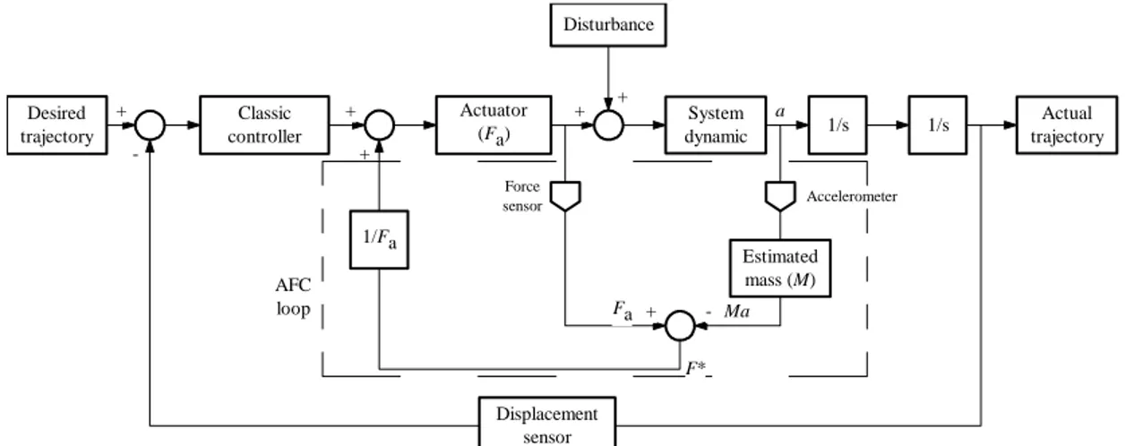
where, F* is the compensated or estimated force, Fa is the measured force of the actuator, M is the estimated mass of the body and a is the measured acceleration of the body. The effective computation of F* shall bring about robust performance of the system in encountering various forms of disturbances. The main drawback of AFC is to appropriately estimate the mass needed in the AFC loop. Figure 3 illustrates the application of AFC scheme to a translational dynamic system. In the figure, it is clear that the overall control system comprises two degrees-of-freedom controller having two control loops, namely the outer loop governed by the classic controller (or other types such as fuzzy logic controller used in the study) and the inner loop which contains the AFC element. Note that the computed estimated force, F* should be fed back into the main AFC the loop through a transfer function (typically 1/ Fa). Practically, the variables to be measured, i.e Fa and a can be easily acquired using physical sensing devices (force sensor and accelerometer) while M can be obtained through heuristic means or intelligent mechanisms. In the study, the latter method was used to appropriately estimate the variable.
Desired trajectory Classic controller 1/Fa Actuator (Fa) Disturbance System dynamic 1/s 1/s Estimated mass (M) Displacement sensor Actual trajectory Accelerometer Force sensor + -+ + + + + -AFC loop a F* Fa Ma
13
5. FUZZY LOGIC CONTROLLER
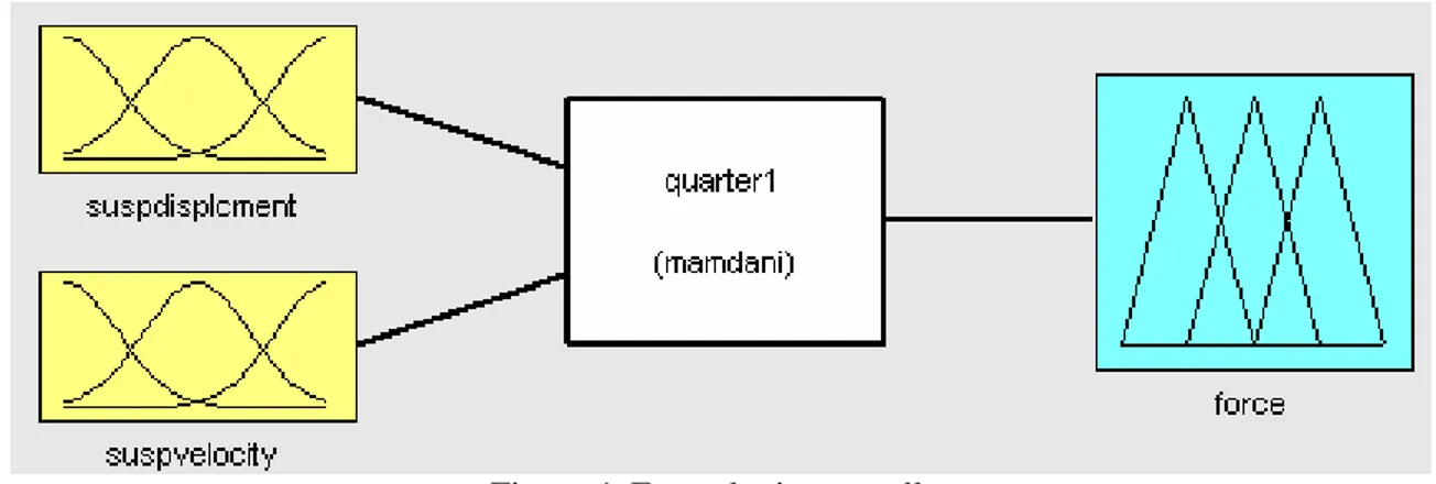
A fuzzy logic control component employed in the study is designed in such a way that it replaces the classic PID controller that is typically used in a control system. Its main objective is to provide the force control signal that shall complement the AFC signal to actuate the non-linear hydraulic actuator. The overall fuzzy logic control procedure typically composed of a number of processes, namely the fuzzification process, establishment of fuzzy rule base and defuzzification process. The first step is fuzzification in which crisp input values are transformed into fuzzy input involving the construction of suitable membership functions representing the fuzzy set. Some of the information for the designand construction of membership functions are obtained through human expert’s judgement and others through results of previous study. This is followed by the process of rules evaluation normally in the form of linguistic statements to determine the dynamics of the controller as a response to the given fuzzy input. It is then passed through a defuzzification process using an averaging technique to produce crisp output values [12]. The structure of the fuzzy logic controller used in the study is shown in Figure 4. Gaussian membership functions is used in the fuzzification procedure and produce favourable outcome. Mamdani’s minimum operation rule (which is a popularly used method) is employed as the fuzzy implication function (inference mechanism), and centre of gravity technique is applied to the defuzzification procedure. The two inputs of the fuzzy logic controller are the suspension deflection and suspension velocity while the output is represented by the force vector which shall become the input to the hydraulic actuator [7] and serves as the initial control signal of the outer control loop. MATLAB with Fuzzy Logic Toolbox and Simulink softwares are used in the simulation study.
Figure 4. Fuzzy logic controller 6. SIMULATION, RESULTS AND DISCUSSION
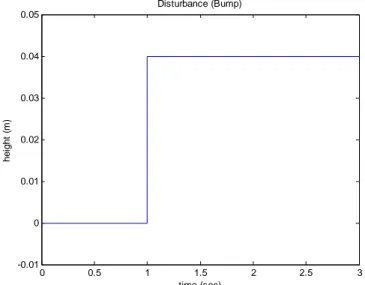
The Simulink diagram of the FLAFC scheme applied to active suspension system is shown schematically in Figure 5. It consists of the PID controller for the hydraulic double acting actuator model, AFC element, vehicle system dynamic model, fuzzy logic controller, disturbances and reference input of the system. Vehicle system dynamic has two inputs which are the road disturbance and actuated force from the hydraulic actuator. This system dynamic meanwhile has four outputs related to the body displacement, suspension deflection, tyre deflection and body acceleration. Road profile as shown in Figure 6, is represented by a step function as a single bump on the road with 4 cm bump height. It is considered as the introduced disturbance for the experimentation of the developed model to verify the system’s robustness. Vehicle system dynamic model is represented by the specific dynamics of the quarter car active suspension system as described by equation (1).
The PID controller parameters are first selected by performing a number of trial runs until satisfactory results are obtained. The output of hydraulic actuator then becomes the input to the quarter car active suspension systems and the AFC component. AFC scheme has two inputs which are related to the actuated force of the hydraulic actuator and body acceleration signals. The estimation of mass needed by
AFC loop is the main factor which contribute to the effectiveness of the control scheme. In this simulation, the estimated mass was acquired using a crude approximation method.
Figure 5.A Simulink diagram of the FLAFC scheme.
0 0.5 1 1.5 2 2.5 3 -0.01 0 0.01 0.02 0.03 0.04 0.05 Disturbance (Bump) time (sec) hei ght ( m )
Figure 6. Road surface represented by a single bump with 4 cm height.
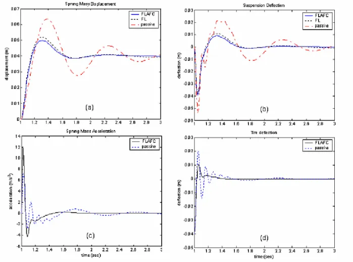
The simulation works have been performed considering the parameters and conditions explained in [5,8] to demonstrate the mass sprung displacement, suspension deflection, tyre deflection when the car hitting the bump when the system is executed. The results of the simulations are graphically shown in Figures 7 (a) to (d). In each case, the solid line shows the response of the proposed FLAFC method, the dotted line shows the response of the fuzzy logic (FL) strategy while the dashed line is for passive suspension. It is very obvious that the FLAFC produces the best performance compared to its counterparts in compensating the introduced disturbance. This shows that the system is more robust and effective.
15
Figure 7. Step response of FLAFC scheme, fuzzy logic and passive suspensions (a) sprung mass displacement (b) suspension deflection
(c) sprung mass acceleration (d) tyre deflection
7. CONCLUSION
A new type of control method in the form of fuzzy logic iterative learning active force control (FLAFC) for an active suspension system has been designed and applied. Result show that for given condition and parameters, the proposed system FLAFC yields improved performance compared to the rest of the systems considered in the study. However, further investigation should be carried out to study the effects of other road conditions (disturbances), different loading conditions, uncertainties and parametric changes.
ACKNOWLEDGEMENTS
The authors would like to thank the Malaysian Ministry of Science and Technology and the Innovationt (MOSTI) and Universiti Teknologi Malaysia (UTM) for their continuous support in the research work. This research was fully supported by an IRPA grant (No. 03-02-06-0123EA001).
REFERENCES
[1] K. Hudha, H. Jamaluddin, P.M. Samin, R.A. Rahman, “Active Roll Control Suspension System (ARCS) Using Active Force Control Strategy on A New Modified Half Car Model”, SAE, 2003.
[2] Z. Omar, Modelling and Simulation of an Active Suspension System Using Active Force Control Strategy, MSc Report, Universiti Teknologi Malaysia, 2002.
[3] Y.M. Sam, Modelling and Control of Hydraulically Actuated Active Suspension Systems, PhD Thesis, Universiti Teknologi Malaysia, 2004.
[4] Barr, A.J.; Ray, J.I, Control of an active suspension using fuzzy logic, Proceedings of the Fifth IEEE International Conference on Fuzzy Systems, Vol. 1, Pages:42 - 48 vol.1, 8-11 Sept. 1996.
[5] M.V.C. Rao, V. Prahlad, “A Tunable Fuzzy Logic Controller for Vehicle Active Suspension Systems”, Fuzzy Set and System, 1997.
[6] F.J. D’Amato, D.E. Viassolo, “Fuzzy Control for Active Suspensions”, Mechatronics, 2000.
[7] J. Campos, F.L. Lewis, L. Davis, S. Ikenaga, “Backstepping Based Fuzzy Control of Active Vehicle Suspension Systems”,American Control Conference, 2000. Proceedings of the 2000, Volume: 6, 28-30 June 2000.
[8] A. Alleyne, R. Liu, H. Wright, “On the Limitations of Force Tracking Control for Hydraulic Active Suspensions”, Proc. Of the American Control Conference, Philadelphia, Pennsylvania, June, 1998. [9] S.B. Hussein, H. Jamaluddin, M. Mailah and A. Zalzala, “A Hybrid Intelligent Active Force Controller
For Robot Arm Using Evolutionary Neural Networks”, Proc. Int'l Conference on Evolutionary Computation (CEC 2000), San Diego, USA, July 2000.
[10] M. Mailah, Intelligent Active Force Control of a Rigid Robot Arm Using Neural Network and Iterative Learning Algorithms, PhD Theses, University of Dundee, 1998.
[11] M. Mailah, N.I.A. Rahim, “Intelligent Active Force Control of a Robot Arm Using Fuzzy Logic”, IEEE International Conference on Intelligent Systems and technologies TENCON 2000, Kuala Lumpur, September 2000.
CHAPTER 2
CONTROL DESIGN OF A QUARTER CAR SUSPENSION SYSTEM USING FUZZY LOGIC ACTIVE FORCE CONTROL
Gigih Priyandoko & Musa Mailah
Presented at International Conference on Mechatronics 2005 (ICOM05), Kuala Lumpur, May 2005
Fuzzy-Neuro Active Force Control of a Quarter Car Suspension System
Gigih Priyandoko, Musa Mailah Intelligent Active Force Control Research Group,
Department of Applied Mechanics, Faculty of Mechanical Engineering, Universiti Teknologi Malaysia, 81310 Skudai, Johor Tel:+6075535942, E-mail: [email protected], [email protected]
Abstract
This paper presents the design of a control technique applied to an active suspension system of a quarter car model using fuzzy logic controller with artificial neural network embedded in the active force control component. The overall control system is decomposed into two loops. In the main loop, the desired force signal is calculated using an active force control strategy with a neural network element being employed to estimate the mass needed to feed the forward control loop. A fuzzy logic controller is implemented in the outer loop to design a force controller such that the desired force signal is achieved in a robust manner. The resulting control strategy known as fuzzy-neuro active force controller (FNAFC), is then used to control a nonlinear actuator attached between the sprung mass and the unsprung mass of the quarter car model. The performances of the proposed control method were then evaluated and later compared to examine the effectiveness in suppressing the vibration effect of the suspension system. It was found that the active suspension system with fuzzy-neuro active force control gives better performance compared to the fuzzy logic and the passive suspension system.
Keywords
Active suspension, quarter car, fuzzy logic control, artificial neural network, active force control.
Introduction
For many years, automobile suspension primarily consists of a coil or leaf spring in parallel with viscous damper. The control of automobile suspensions is currently of great interest in both the academic and industrial fields. Suspension design requires a compromise between the passenger comfort and good handling vehicle. To provide a good ride comfort, the suspension should be soft enough, but whereas good road holding requires stiff suspension. A good vehicle suspension should be able to minimize the vertical displacement and the acceleration of the body, however, in order to increase the passenger comfort, the sprung mass displacement need to be minimized. In the conventional passive suspension system, the mass-spring-damper parameters are generally fixed, and they are chosen based on the design requirements of the vehicles. The suspension has the ability to store energy in the spring and to dissipate it through the damper. When a spring supports a load, it will compress until the force produced by the compression is equal to the load force. If some other forces then disturb the
load, then the load will oscillate up and down around its original position for some time. Passive suspension utilizing mechanical springs and dampers is known to have the limitations of vibration isolation and lack of attitude control of the vehicle body. To solve these problems, many researchers have studied various active and semi-active suspensions both theoretically and experimentally. In semi active suspension systems, it still uses springs as the main form of support, however the dampers can be controlled. A semi active suspension has the ability to change the damping characteristics of the shock absorbers without using any actuators. Active suspension differs from the conventional passive suspension in its ability to inject energy into the system. In an active suspension system, an actuator is attached in parallel with both a spring and a shock absorber. To achieve the desired performance, actuator should generate the desired force in any direction, regardless of the relative velocity across it. The ability to control the energy from external source according to the environment provides better performance of suspension system. For this reason, the active suspension has been widely investigated [1-5]. The objective of this study is to design a controller of active suspension system that can reduce the vertical body displacement, suspension deflection, tyre deflection and body acceleration using fuzzy logic neural network active force control (FNAFC) strategy.
Dynamics Equations of an Active Suspension The model of the quarter car active suspension system used is shown in Figure 1. zs zu zr fa bs ks kt ms sprung mu unsprung road terrain Figure 1 - A Quarter Car Active Suspension
19
The quarter car model is presented by a two degrees-of-freedom model. The equations of motion for this system are given as [3]: a r u t u s s u s s u u a u s s u s s s s f z z k z z b z z k z m f z z b z z k z m − − − − + − = + − − − − = ) ( ) ( ) ( ) ( ) ( & & && & & && (1) where
ms is the sprung mass (body) mu is the unsprung mass (wheel) bs is the damping coefficient ks is the spring stiffness kt is the tyre stiffness fa is the actuator force
zs is the displacement of the car body zuis thedisplacement of wheel zr is the displacement of road zs–zu is the suspension deflection zu – zr is the tyre deflection
s
z& is the velocity of the car body
u
z& is the velocity of wheel
By assuming that the suspension spring and tyre stiffnesses are linear in their operating ranges, the tyre does not leave the ground. The displacements of both the body and wheel can be measured from the static equilibrium point.
Dynamic Equations of A Hydraulic Actuator Figure 2 depicts a schematic diagram of a translational double acting hydraulic actuator driven by a three-land four-way spool valve. An actuator is assumed to be placed between the sprung and unsprung masses and can exert a force fa in between ms and mu.
Figure 2 - Double Acting Hydraulic Actuator
The hydraulic actuator is assumed to consist of a spool valve (servo valve) and a hydraulic cylinder. Ps and Pr are the
supply and return pressures going into and out of the spool valve, respectively. xsp is spool valve position. Pu and Pl are
the oil pressure in the upper and lower cylinder chambers.
xw-xc is the hydraulic piston displacement.
The differential equation governing the dynamics of the actuator is given in [3] as follows:
) ( 4 L L tm L s u t z z A P C Q P V & & & = − − − β (2)
where Vt, βe , A and Ctm are the total actuator volume,
effective bulk modulus, actuator ram area and coefficient of total leakage due to pressure respectively.
Using the equation for hydraulic fluid flow through an orifice, the relationship between spool valve displacement xv
and the total flow QL is given as [3]:
ρ v L s v d L P x P wx C Q = −sgn( ) (3)
where Cd and w are discharge coefficient and spool valve
gradient respectively.
Active Force Control
Active force control (AFC) strategy was first proposed by Hewit and co-workers to control a dynamic system in order to ensure the system remain stable and robust in the presence of known and unknown disturbances [6]. AFC has been demonstrated to be superior compared to conventional methods in controlling a robot arm [7,8,6]. AFC can be shown to complement the basic Newton’s second law of motion, i.e. for a translational system,
∑
F=ma, where F is the sum of all forces acting on the body, m is the mass of the body and a is the acceleration. The concept of AFC is to use some measured and estimated values of the identified system parameters namely the actuated forces, acceleration of the body and the estimated mass of the body. The basic AFC equation can then be written as follows:' ' ' F ma
F= − (4)
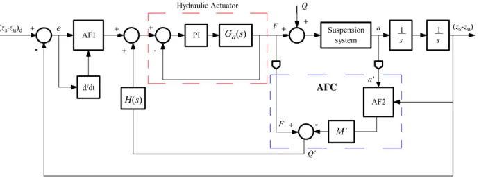
where the superscript (’) denotes the measured or estimated values of the parameters. Figure 3 illustrates the principle of AFC applied to a translational system. The measurable physical quantities of the system are the actuating force (F) and the acceleration (a’). These can be measured using force sensor and acceleration sensor, respectively. The estimated mass (m’) of the system with the presence of disturbances that contributes to the acceleration should be estimated appropriately. If all the parameters are successfully acquired, then the resulting estimated force (F’) from equation (4) should result in a very robust and stable performance of the control system once this signal is fed back to the AFC control loop.
desire track System Dynamic 1/s 1/s actual track disturbance 1/Q estimate mass displacement tranducer accelerometer actuator (Q) controller + + + + + + -force sensor
Active Force Control (AFC)
Figure 3 –A Schematic Diagram of AFC Strategy
Neural Network
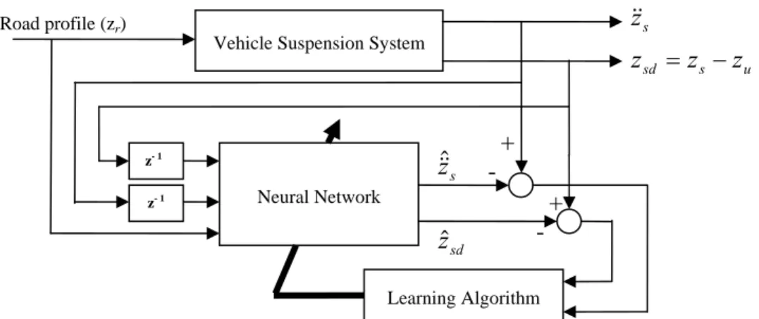
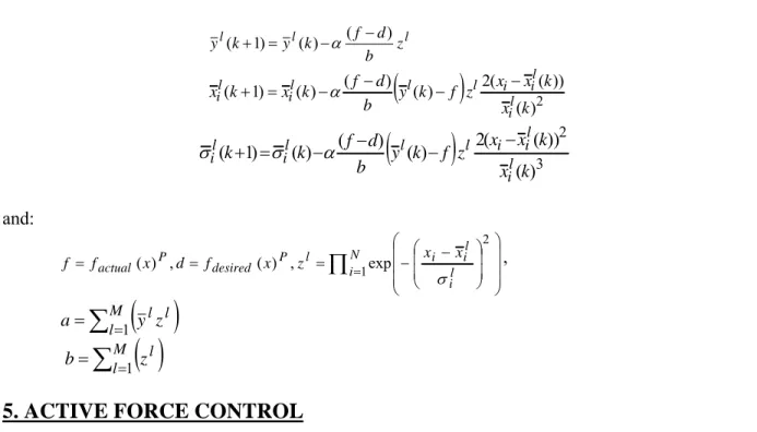
A neural network is an information processing paradigm that is inspired by the way biological nervous systems, such as the brain, process information. The key element of this paradigm is the novel structure of the information processing system. It is composed of a large number of highly interconnected processing elements (neurons) working in unison to solve specific problems. A trained neural network can be thought of as an expert in the category of information it has been given to analyze. An ability to learn how to do tasks based on the data given for training or initial experience. The structure of neural network in this research is shown in Figure 4. Neural network has three layers, input layer, hidden layer and output layer, respectively. Input layer has two inputs, sprung mass displacement and error system. Hidden layer has three neurons and output layer has one neuron. In order to train the weights of neural network the back propagation method is used uaing the following adaptation algorithm based on a gradient descent method.
k a d k k w y y w w ∂ − ∂ + = +1 η ( ) (5)
where wk+1 is the next step weight, wk is the current step
weight, η is the learning constant, yd is the desired output
and ya is the actual output. The neural network is used for
the approximation of the estimated mass needed by the AFC loop. Neural network training shall be accomplished in an off-line manner until satisfied tracking performance is achieved. Later, the fully trained neural network is implemented on-line as it is embedded into the overall control scheme.
hidden layer output layer input layer
input 2 input 1
output
Figure 4 - Neural Network Structure
Fuzzy Logic Controller
The fuzzy logic controller employed in the study is composed of fuzzification, establishment of fuzzy rule base and defuzzification [9]. The first step is fuzzification in which crisp input values are transformed into fuzzy input involving the construction of suitable membership functions representing the fuzzy set. This is followed by the process of rules evaluation normally in the form of linguistic statements to determine the dynamics of the controller as a response to the given fuzzy input. It is then passed through a defuzzification process using an averaging technique to produce crisp output values.
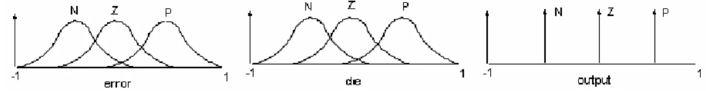
The structure of a fuzzy logic controller is shown in Figure 5. The seven Gaussian membership functions are used in fuzzification. Mamdani’s minimum operation rule is used as a fuzzy implication function, and centre of gravity method is used for defuzzification. The two inputs of the fuzzy logic controller are suspension deflection and suspension velocity while the output is represented by the force vector which shall become the input to the hydraulic actuator [1,4].
suspension deflection
suspension velocity
output
Figure 5 - Fuzzy Logic Controller
Simulation, Results and Discussion
The Simulink diagram of the FNAFC strategy for active suspension system is shown in Figure 6. It consists of the hydraulic double acting actuator model, suspension system dynamic model, neural network, fuzzy logic control, disturbances and reference input of the system.
The system dynamic has two inputs which are road disturbance and active force from hydraulic actuator. This block has four outputs which are the body (sprung mass) displacement, suspension deflection, tyre deflection and body acceleration.
21
Figure 6 - A Schematic Diagram of FNAFC Strategy
The road profile is shown in Figure 7 which is represented by three bumps on the road with 2 cm, 3 cm and 1 cm bump heights respectively. It is considered as a form of ‘disturbance’ to the system. The output of the hydraulic actuator then becomes the inputs of system dynamics within the AFC control loop. The AFC scheme has two inputs, namely the active force hydraulic actuator and body acceleration components. The estimation of mass needed by AFC loop is the main factor which contribute to the effectiveness of the control scheme. In this simulation, in order to estimate the mass needed to feed the forward AFC loop, neural network strategy is used.
Figure 7 - Road ProfileUsed in the Study
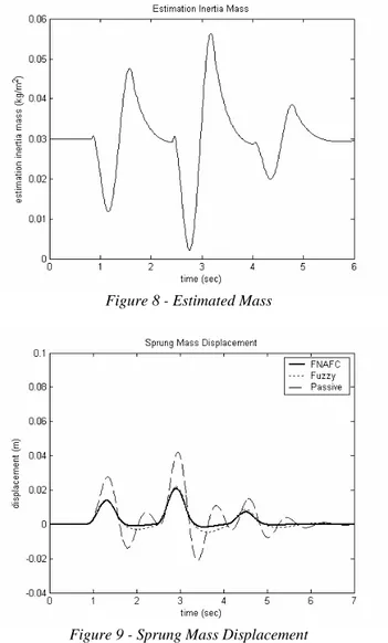
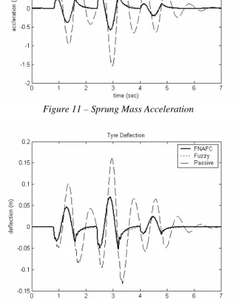
The simulation works have been done with the parameters and condition explained in [1,3,4] and demonstrate that mass sprung displacement, suspension deflection, tyre deflection when the car hitting the bump. Limit suspension deflection is ± 4 cm. The results for simulations described are given in Figures 8 to 12. In each case, the solid line shows the response of the FNAFC strategy, the dotted line shows the response of the fuzzy logic control strategy and the dashed line shows the response of the passive suspension system. It is obvious that the FNAFC produces the best performance than its counterparts in compensating the introduced
disturbance. This shows that the system is more robust and effective.
Figure 8 - Estimated Mass
Figure 9 - Sprung Mass Displacement
Figure 11 – Sprung Mass Acceleration
Figure 12 – Tyre Deflection
Conclusion
The resulting control strategy known as fuzzy-neuro active force controller (FNAFC) has been shown to be robust and effective in controlling the suspension system. It was found that the active suspension system with fuzzy-neuro active force control gives better performance compared to the fuzzy logic and the passive suspension systems. All the four main parameters related to body displacement, suspension deflection, body mass acceleration, and tyre deflection have been desirably reduced through the control strategy. This may contribute to improved road handling and riding comfort of the automotive system.
Acknowledgments
The authors would like to thank the Malaysian Ministry of Science and Technology and the Innovationt (MOSTI) and
Universiti Teknologi Malaysia (UTM) for their continuous support in the research work. This research was fully supported by an IRPA grant (No. 03-02-06-0123EA001).
References
[1] Rao, M.V.C., Prahlad, V. 1997. A Tunable Fuzzy Logic Controller for Vehicle Active Suspension Systems,
Fuzzy Sest and System, 11-21.
[2] D’Amato, F.J., Viassolo, D.E. 2000. Fuzzy Control for Active Suspensions, Mechatronics, (24):897-920. [3] Alleyne, A., Liu, R., Wright, H. 1998. On the
Limitations of Force Tracking Control for Hydraulic Active Suspensions. In the Proceedings of the American Control Conference, 43-47. Philadelphia, Pennsylvania. [4] Barr, A.J.; Ray, J.I. 1996, Control of An Active
Suspension Using Fuzzy Logic. In Proceedings of the Fifth IEEE International Conference on Fuzzy Systems, Vol. 1, 42 - 48.
[5] Campos, J., Lewis, F.L., Davis, L., Ikenaga, S. 2000. Backstepping Based Fuzzy Control of Active Vehicle Suspension Systems. In Proceedings of the American Control Conference, Vol. 6: 28-30.
[6] Hewit, J. R. and Burdess, J.R. 1981. Fast Dynamic Decoupled Control for Robotics Using Active Force Control, Transaction on Mechanism and Machine Theory, 16(5): 535-542.
[7] Mailah, M., Rahim, N.I.A. 2000. Intelligent Active Force Control of a Robot Arm Using Fuzzy Logic. In Proceedings of IEEE International Conference on Intelligent Systems and Technologies TENCON 2000, Vol. II: 291-297. Kuala Lumpur.
[8] Hussein, S.B, Jamaluddin, H., Mailah M. and Zalzala, A. 2000, A Hybrid Intelligent Active Force Controller For Robot Arm Using Evolutionary Neural Networks, In Proceedings of the International Conference on Evolutionary Computation (CEC 2000), 117-124. San Diego, USA.
[9] Negnevitsky, M. 2005, Artificial Intelligence: A Guide to Intelligent Systems, 2nd Edition, Addison Wesley.
CHAPTER 3
FUZZY-NEURO ACTIVE FORCE CONTROL OF A QUARTER CAR SUSPENSION SYSTEM
Gigih Priyandoko & Musa Mailah
Presented at International Conference on Robotics, Vision and Signal Processing 2005 (ROVISP05), Penang, May 2005
Particle Swarm Optimization Neural Network Based Modelling of
Vehicle Suspension System
Gigih Priyandoko Musa Mailah Hishamuddin Jamaluddin
Department of Applied Mechanics,Faculty of Mechanical Engineering, Universiti Teknologi Malaysia, 81310 Skudai, Johor Bahru, Malaysia e-mail: [email protected] [email protected] [email protected]
Abstract
T
his paper presents a novel method for the modelling of a quarter car vehicle suspension system using a Neural Network (NN) technique incorporating Particle Swarm Optimization (PSO) method. The proposed neural network model is shown to be simple in topology and accurate in identification. The PSO element is able to speed up the convergence rate compared to the traditionally slow back-propagation (BP) learning algorithm that is typically employed as one of the most common supervised training methods in a multilayer NN configuration. The design and structure of the scheme based on this approach are adequately described and discussed with the input and output data acquired from a running quarter car test rig. Simulation results from the study show that the NN with PSO as learning method performs better than the BP learning algorithm in executing the proposed task.Keywords:
Vehicle suspension, modelling, neural network, back-propagation, particle swarm optimization.
1. Introduction
Modelling of a vehicle has been studied for a long time in order to design a high-performance vehicle controller. In the past, most vehicle models have been constructed analytically in the form of dynamic equations. A conventional vehicle model, however, suffers from structural complexity, long development time, and the difficulty of modelling the highly nonlinear terms and the measurement noise. In order to control a real vehicle beyond mere simulation, it is indispensable to model the vehicle quickly, easily, and accurately [1]. In paper [2], the authors develop a comprehensive nonlinear model of a vehicle suspension system. This model is derived using the standard kinematics and kinetics and takes into consideration a number of factors that are neglected in most existing models. Typical control strategies rely on linear and time-invariant models. Buckner et al. [3] use neural network that continually learns and estimates the nonlinear parameter variations of a quarter-car suspension model. This estimation algorithm becomes the foundation for an Intelligent Feedback Linearization controller for active vehicle suspensions. Billings et al. [4] demonstrated that NNs could be used successfully for the identification and control of non-linear dynamical systems. The most advantageous and distinguishing feature of NNs is their ability to learn. The network in the adaptive mode abstracts and generalizes the function character in the process of learning from
training patterns. The learning algorithm is an optimization method capable of finding weight coefficients and thresholds (learning rates) for a given neural network and a training set. The learning algorithm that is used most frequently is the backpropagation (BP) method. Although BP training has proved to be efficient in many applications, its convergence tends to be slow, and yields to suboptimal solutions [7]. To counter this problem, a particle swarm optimization (PSO) technique is proposed and used in the study. Generally, the PSO is characterized as a simple heuristic of a well balanced mechanism with flexibility to enhance and adapt to both global and local exploration abilities. It is a stochastic search technique with reduced memory requirement, computationally effective and easier to implement [9].
The paper is organized as follows: Section II describes the dynamics of the vehicle suspension system while section III presents the structure of the NNs using BP learning algorithm. Section IV describes the Particle Swarm Optimization technique. The results of the simulation study are discussed and presented in section V. Finally, the paper is concluded in section VI.