DOI 10.1007/s11214-007-9266-3
The Mercury Dual Imaging System on the MESSENGER Spacecraft
S. Edward Hawkins, III·John D. Boldt·Edward H. Darlington·Raymond Espiritu· Robert E. Gold·Bruce Gotwols·Matthew P. Grey·Christopher D. Hash·
John R. Hayes·Steven E. Jaskulek·Charles J. Kardian, Jr.·Mary R. Keller· Erick R. Malaret·Scott L. Murchie·Patricia K. Murphy·Keith Peacock· Louise M. Prockter·R. Alan Reiter·Mark S. Robinson·Edward D. Schaefer· Richard G. Shelton·Raymond E. Sterner, II·Howard W. Taylor·
Thomas R. Watters·Bruce D. Williams
Received: 24 July 2006 / Accepted: 10 August 2007 / Published online: 23 October 2007
© Springer Science+Business Media B.V. 2007
Abstract The Mercury Dual Imaging System (MDIS) on the MESSENGER spacecraft will provide critical measurements tracing Mercury’s origin and evolution. MDIS consists of a monochrome narrow-angle camera (NAC) and a multispectral wide-angle camera (WAC).
The NAC is a 1.5° field-of-view (FOV) off-axis reflector, coaligned with the WAC, a four- element refractor with a 10.5° FOV and 12-color filter wheel. The focal plane electronics of each camera are identical and use a 1,024×1,024 Atmel (Thomson) TH7888A charge- coupled device detector. Only one camera operates at a time, allowing them to share a com- mon set of control electronics. The NAC and the WAC are mounted on a pivoting platform that provides a 90° field-of-regard, extending 40° sunward and 50° anti-sunward from the spacecraft+Z-axis—the boresight direction of most of MESSENGER’s instruments. On- board data compression provides capabilities for pixel binning, remapping of 12-bit data into 8 bits, and lossless or lossy compression. MDIS will acquire four main data sets at Mer- cury during three flybys and the two-Mercury-solar-day nominal mission: a monochrome
S.E. Hawkins, III (
)·J.D. Boldt·E.H. Darlington·R.E. Gold·B. Gotwols·M.P. Grey·J.R. Hayes· S.E. Jaskulek·C.J. Kardian, Jr.·M.R. Keller·S.L. Murchie·P.K. Murphy·K. Peacock·L.M. Prockter·R.A. Reiter·E.D. Schaefer·R.G. Shelton·R.E. Sterner, II·H.W. Taylor· B.D. Williams
The Johns Hopkins University Applied Physics Laboratory, Laurel, MD 20723, USA e-mail: [email protected]
R. Espiritu·C.D. Hash·E.R. Malaret
Applied Coherent Technology, Herndon, VA 20170, USA M.S. Robinson
School of Earth and Space Exploration, Arizona State University, Box 871404, Tempe, AZ 85287-1404, USA
T.R. Watters
Center for Earth and Planetary Studies, National Air and Space Museum, Smithsonian Institution, Washington, DC 20013, USA
global image mosaic at near-zero emission angles and moderate incidence angles, a stereo- complement map at off-nadir geometry and near-identical lighting, multicolor images at low incidence angles, and targeted high-resolution images of key surface features. These data will be used to construct a global image base map, a digital terrain model, global maps of color properties, and mosaics of high-resolution image strips. Analysis of these data will provide information on Mercury’s impact history, tectonic processes, the composition and emplacement history of volcanic materials, and the thickness distribution and compositional variations of crustal materials. This paper summarizes MDIS’s science objectives and tech- nical design, including the common payload design of the MDIS data processing units, as well as detailed results from ground and early flight calibrations and plans for Mercury image products to be generated from MDIS data.
Keywords MESSENGER·Mercury·Imaging·Camera·Imager·CCD·Heat pipe·Wax pack·Photometry·Stereo
1 Introduction
Mariner 10, from its three flybys of Mercury in 1974–1975, provided a reconnaissance view of one hemisphere and measured the planet’s magnetic field and interaction with the space environment. No spacecraft has returned in the intervening 30 years, however, and our knowledge of Mercury’s composition, origin, and evolution is therefore limited. From its high bulk density, Mariner 10 observations (Murray1975), and Earth-based remote sensing, Mercury is known to have a high metal-to-silicate ratio, a crust low in FeO (Rava and Hapke 1987; Vilas1988; Blewett et al.1997; Robinson and Taylor2001), and an exosphere with such species as Na and K (Potter and Morgan,1985,1986). Even though our understanding of Mercury’s bulk composition is limited, some constraints on models of planetary formation and evolution are possible. If Mercury condensed from the inner refractory portion of a hot early nebula, it should be strongly deficient in volatiles and FeO (e.g., Lewis1972,1974).
The possibility that Mercury’s semimajor axis experienced large excursion during growth of the inner planets (Wetherill1994) is permissive of Mercury having greater fractions of volatiles and FeO.
Mariner 10 images showed a heavily cratered surface grossly similar to that of the Earth’s Moon (Murray et al.1975; Spudis and Guest1988). One of the more distinctive morphologic features discovered by Mariner 10 is a class of tectonic features known as lobate scarps, interpreted to reflect large-scale contractional deformation of Mercury’s crust. Lobate scarps are thought to be the surface expression of thrust faults formed as the planet’s interior cooled and contracted, possibly during a period in which tidal despinning was also occurring (Strom et al.1975; Cordell and Strom1977; Melosh and Dzurisin1978; Pechmann and Melosh 1979; Melosh and McKinnon1988; Watters et al.2004). Another distinguishing feature of Mercury is the smooth plains. Smooth plains are comparable in morphology to lunar mare deposits, but they lack the distinctive low albedo of their lunar counterparts, because of the very low FeO content (Trask and Guest1975; Strom1977; Kiefer and Murray1987;
Rava and Hapke1987; Spudis and Guest1988). Whether the smooth plains are volcanic or impact deposits is still debated (Wilhelms1976; Kiefer and Murray1987; Robinson and Lucey1997).
Earth-based radar images of Mercury rival those obtained by Mariner 10 (Harmon et al.
2001). More importantly, radar led to the discovery of an anomalous class of materials inside permanently shadowed crater interiors in both polar regions. These materials exhibit high
radar reflectivity and a circular polarity inversion consistent with a volume scatterer (Slade et al.1992; Harmon and Slade1992). Water ice remains the leading candidate material to explain the shadowed deposits, but many unanswered issues remain and final resolution must await orbital observations (Harmon et al.2001).
The MErcury Surface, Space ENvironment, GEochmistry, and Ranging (MESSENGER) spacecraft was conceived, designed, and built to address six fundamental science questions regarding the formation and evolution of Mercury (Solomon et al.2001). (1) What planetary formational processes led to the planet’s high metal-to-silicate ratio? (2) What is Mercury’s geological history? (3) What are the nature and origin of Mercury’s magnetic field? (4) What are the structure and state of Mercury’s core? (5) What are the radar-reflective materials at Mercury’s poles? (6) What are the important volatile species and their sources and sinks on and near Mercury?
The process of selecting the scientific instrumentation to investigate these diverse ques- tions balanced the available mission resources for mass, power, mechanical accommodation, schedule, and money. For MESSENGER, the mass and mechanical accommodation issues were very significant design constraints. The payload mass was limited because of the large amount of propellant needed for orbital insertion. The mechanical accommodation was dif- ficult because of the unique thermal constraints faced in the mission. Taking into account all these factors, MESSENGER carries seven miniaturized instruments (Gold et al.2003): the Mercury Dual Imaging System (MDIS), Gamma-Ray and Neutron Spectrometer (GRNS), X-Ray Spectrometer (XRS), Mercury Laser Altimeter (MLA), Magnetometer (MAG), Mer- cury Atmospheric and Surface Composition Spectrometer (MASCS), and Energetic Particle and Plasma Spectrometer (EPPS). Additionally, a radio science investigation will address key measurements such as Mercury’s physical libration and gravity field.
The MESSENGER spacecraft was launched from Cape Canaveral on August 3, 2004, in a spectacular nighttime launch. On August 1, 2005, the spacecraft successfully completed an Earth gravity assist to slow the spacecraft and redirect it toward the inner solar system. En route to its primary mission at Mercury, MESSENGER experiences two Venus flybys and three Mercury flybys. The first Venus flyby occurred on October 24, 2006, and the second occurred on June 5, 2007. The three Mercury flybys will take place on January 14, 2008, October 6, 2008, and September 29, 2009, during which regions unexplored by Mariner 10 will be imaged by MDIS. Mercury orbit insertion will occur on March 18, 2011, and the spacecraft will begin the orbital phase of its mission, which is one Earth year in duration.
The orbital mission is slightly longer than two Mercury solar days.
2 MDIS Measurement Objectives and Design Implementation
MDIS consists of two cameras, a monochrome narrow-angle camera (NAC) and a multi- spectral wide-angle camera (WAC), coaligned on a common pivot platform. The passively cooled detectors in each camera are thermally tied to its complex thermal system. This arrangement allows the detectors to be maintained within their operating temperature, even during the hottest portion of the orbit at Mercury. The pivot platform provides an added de- gree of freedom to point the dual cameras with minimal impact on the spacecraft. The full design details of the instrument are given in Sect.3. Specifications of the two cameras, given in Table1, are tailored to the orbit and imaging requirements of the MESSENGER mission.
MESSENGER will be placed in a highly eccentric orbit with a periapsis altitude of 200 km, a periapsis latitude of∼60°N, and an apoapsis altitude of 15,200 km. The orbit has a 12-hour period, is inclined 80° to the planet’s equatorial plane, and is not Sun synchro- nous. During one Mercury solar day (noon to noon), the planet completes three full rotations
Table 1 MDIS camera specifications
Narrow angle Wide angle
Field of view 1.5°×1.5° 10.5°×10.5°
Pivot range −40° to+50°
(observational) (Sunward) (Planetward)
Exposure time 1 ms to∼10 s Frame transfer time 3.84 ms Image readout timea 1 s
Spectral filters 1 12 positions
Spectral range 700–800 nm 395–1,040 nm
Focal length 550 mm 78 mm
Collecting area 462 mm2 48 mm2
Detector-TH7888A CCD 1024×1024, 14-µm pixels
IFOV 25 µrad 179 µrad
Pixel FOV 5.1 m at 200-km altitude 35.8 m at 200-km altitude
Quantization 12 bits per pixel
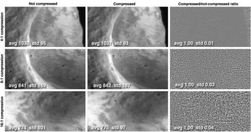
Hardware compression Lossless, multi-resolution lossy, 12-to-nbits
MDIS Assembly MDIS DPU-A or -B
Mass 7.8 kg 1.5 kg
Powerb 7.6 W 12.3 W
Footprint 398×270×318 mm 157×117×104 mm
Data rate 16 Mbps (to DPU) 3 Mbps (to SSR)
aTransfer to DPU
bNominal power configuration (DISE+NAC or WAC; DPU+MDIS motor + resolvers)
relative to the spacecraft orbital plane. At times the ground track is near the terminator (the
“dawn–dusk orbit”); 22 days later it passes over the subsolar point (the “noon–midnight”
orbit).
The two primary imaging objectives during the flybys are (1) acquisition of near-global coverage at∼500 m/pixel, and (2) multispectral mapping at∼2 km/pixel. During the flyby departures, large portions of the planet will be viewed at uniform low phase angles.
From orbit, gaps in color imaging acquired during the flybys will be filled with images taken at a wide variety of lighting geometries. Total flyby coverage will exclude only the polar regions and two narrow longitudinal bands. The flybys each have one of two basic geometries (Table2), and similar observation strategies will be used for each (Table3).
During the flyby phase, 85% of the planet will be imaged in monochrome at a resolution averaging∼500 m/pixel, and greater than 60% will be imaged in color at about 2 km/pixel.
Half of the planet will be covered in color at∼1 km/pixel. High-resolution NAC swaths will contain monochrome images at better than 125 m/pixel.
During the orbital phase of the mission the MDIS observation strategy will shift to acqui- sition of four key data sets: (1) a nadir-looking monochrome (750-nm) global photomosaic at moderate solar incidence angles (55°–75°) and 250 m/pixel or better sampling; (2) a 25°-off-nadir mosaic to complement the nadir-looking mosaic for stereo; (3) completion of the multispectral mapping begun during the flybys; and (4) high-resolution (20–50 m/pixel) image strips across features representative of major geologic units and structures.
Table 2 Key parameters describing the three MESSENGER Mercury flybys
Date CA CA Inbound Outbound Illuminated Key features
altitude lon lon lon lon
1/14/08 200 40° 308° 132° 276° to 96° Caloris, EUH
10/06/08 200 230° 136° 324° 94° to 274° Kuiper, WUH, MG
09/29/09 200 212° 108° 315° 90° to 270° Kuiper, WUH, MG
All closest approach (CA) latitudes are near-equatorial, and range is listed in kilometers; closest approach occurs on the nightside of the planet for all three flybys. The columns “Inbound lon” and “Outbound lon”
indicate subspacecraft longitudes at 20,000 km range during the inbound and outbound legs of the respective flyby. Comments indicate the portion of Mercury imaged during each flyby (Caloris=Caloris basin, EUH= eastern half of hemisphere unseen by Mariner 10, Kuiper=Kuiper crater, WUH=western half of hemi- sphere unseen by Mariner 10, MG=Mariner 10 gore). All longitudes are positive east. During the three Mariner 10 flybys Mercury was illuminated from 350°E to 170°E
Both the nadir and off-nadir image mosaics will be acquired with the NAC for southern latitudes when altitude is high and with the WAC at lower altitudes over the northern hemi- sphere. This two-camera strategy results in near-uniform global coverage with an average spatial resolution of 140 m/pixel. The off-nadir mosaic will be acquired under nearly identi- cal lighting geometries to the nadir map to facilitate automated stereo matching. The global digital elevation model derived from stereo imaging will have a spatial resolution of 1–4 km horizontally and 100–500 m vertically, depending on latitude. MDIS stereo imaging will be the main source of surface elevation mapping for the southern hemisphere, as MLA’s 1,000-km slant range (Cavanaugh et al.2007) largely limits laser altimetry to the north- ern hemisphere. Filling gaps in color coverage is a relatively simple matter of pointing at and imaging a particular location during times of favorable lighting, except at low altitudes over high northern latitudes. At northern mid-latitudes, low spacecraft altitudes will limit viewing opportunities and probably require gap-filling images to be taken in long strips.
At the time of writing, the strategy for gap-filling of flyby color mapping is still being de- fined. High-resolution NAC imaging is effectively limited by ground motion smear to about 20 m/pixel in the along-track direction; accurate postprocessing correction for electronics artifacts (Sect.4.3) requires exposure times of∼7 ms or longer, equivalent to<20 m of along-track motion smear.
2.1 Science Traceability
The flowdown of requirements from science objectives to instrument design and data acqui- sition strategy are summarized in Table4, which also compares the instrument requirements to as-built performance. Key constraints on the design of the MDIS investigation are the spacecraft’s thermal environment, its highly eccentric orbit, the vertical accuracy required of stereo imaging, the low downlink rates, and the need to support optical navigation (opnav) prior to each Mercury flyby.
At Mercury, the intensity of the solar radiation varies from about 7 to 10 times the to- tal irradiance falling on the Earth. A large sunshade protects MESSENGER from this in- tense solar illumination but constrains the spacecraft pointing ability (Leary et al.2007).
To support optical navigation during the flybys, Mercury will be imaged against the star background; MDIS thus had to be designed to image at phase angles as high as 140°. At the other extreme, flyby science observations require imaging at phase angles of 32°. To compensate for the restricted pointing capability of the spacecraft imposed by the sunshade,
Table3Mercuryflybyimagingplan Descriptionkm/FiltersPixelApprox.Bits/WaveletCum.Cum.Gib,Cum.Gib,Cum.Gib, pixbinninghardwarepixelcomp.imagesuncom-hardwarecom- comp.ratiopressedcom-pressedb ratiopressed Approachopnavs1–1.312160.0700.0540.054 Approachmovie1–2.5812360.3050.1480.062 Approachcolorimage511–1.3122470.4340.2470.111 Approachmosaic0.51–2.588870.7460.3720.127 High-resolutionmosaic10.061–2.5881471.2150.5590.151 High-resolutioncolormosaic111–1.31222462.3751.4520.597 Colorphotometrysequencea–112×21.31223452.6651.6750.708 High-resolutionmosaic20.21–2.5884993.8682.1560.768 Departurecolormosaic211–1.31225985.0283.0491.215 1stdeparturemosaic0.41–2.5866975.8023.3581.266 2nddeparturemosaic0.51–2.5867966.5753.6671.318 Departurecolorimage511–1.31228076.7043.7671.367 3rd(stereo)mosaic0.71–2.5868426.9783.8761.386 4th(stereo)mosaic0.81–2.5868777.2513.9851.404 Departureopnavs1–1.31218837.3214.0391.458 Departuremovie1–2.58129137.5564.1331.466 aSamespotatphaseangles50°–130°in10°increments bTotalspaceavailableonsolid-staterecorderis8Gib
Table4aDerivedMDISrequirementsandas-builtperformanceforfield-of-view,pointing,andspatialresolution Measurement objectiveMeasurementrequirementInstrument/spacecraftrequirementAs-builtperformanceMethodof verification Flybynearglobal monochromemap at500m/pixel ImageMercuryoutboundonallthree flybys;maximizeareaimagedinorbit atnear-0°emissionangle Pointfromnadirto>40°antisunward, >50°sunwardmaintainingunobstructed FOV
UnobstructedFOVto64°antisunward,52° sunwardusingpivotandspacecraftslewBydesign Provideoptical navigationsupport forMercury flybys
Opnavsearlierthanencounter(E)–2. 5daysatflybysAvailabilityofimagingat31°–142°phaseanglesatcenterofFOV,fromcombinationof pivotingandspacecraftslewing,provides: •NACimagingatE-6.0days@flyby1,E-3.7days@flyby2,E-7.2days@flyby3 •WACimagingatE-7.0days@flyby1,E-4.7days@flyby2,E-8.0days@flyby3 Trajectoryanalysis Near-nadirglobal monochromemap at250m/pixel
FOVwideenoughforcross-track continuity,averagedaysidealtitude>9.3°WACFOVforbaselineorbit(>160 µradpixel)10.5°WACFOV(179µradpixel)Geometriccalibration Cross-trackcontinuitymaintainedat lowestaltitudesusingpivotingofFOV1.1°/spivotratetostaggerWACFOVsto produce15°widecompositeimagestrips1.1°/sPivottesting Acquireimagestripswithoutcross- trackgoresorexcessivecross-track overlap
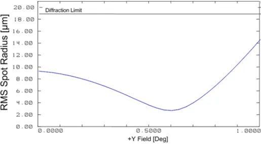
Acquirerectangularsubframesatupto 1HztomanagedownlinkvolumeArbitrarilydefinedrectangularsubframes availableat1HzSpacecraftfunctional testing <250m/pixelsampling,globally, withlowemissionangleWACandNACIFOVsprovide<250 m/pixelaveragesamplingfornominalorbit140m/pixelaveragesamplingofsurfaceat optimallightingCoveragesimulations WACandNACPSFsupportsamplingat <2×averagerequirementProjectedFWHMofNACPSF∼700min southernhighlatitudes;ongroundPSFmea- surementtobeusedforimagerestoration Radiometric calibrationand analyticalmodeling Mainprocessoranddownlinkvolumeallow averagespatialresolutionofbinnedpixels <250m/pixelwithmoderatecompression
25.9GbMDISdownlink(d/l)allocation allowsd/lof140m/pixelusing8:1com- pression;MPloadingrequireson-chip 2×2binningforportionofdata, degradingresolutionbyupto2×
Coverageand spacecraft performance simulations Pointwithsufficientaccuracytoallow mosaickingwith<10%imageoverlap<0.15°pointingaccuracyforspacecraftto maintain<10%NAimageoverlap0.02°pointingaccuracyforspacecraft; 0.03°including1-σuncertaintySimulationbasedon uncertaintiesfrom componenttests <0.15°stepforMDISpivotmechanism0.01°stepforMDISpivotmechanismBydesign Underlineditemsincuradditionaldataprocessingorrevisionstothedataacquisitionstrategytomeetrequirements,asindicated
Table4bDerivedMDISrequirementsandas-builtperformanceforspacecraftslewing,stability,memory,anddownlink Measurement objectiveMeasurementrequirementInstrument/spacecraftrequirementAs-builtperformanceMethodof verification Near-nadirglobal monochromemap at250m/pixel Rollspacecraftsufficientlyrapidlyto tracknadirattheminimum200-km orbitalaltitude 1.35mrad/s1.7mrad/sSpacecraftfunctional testing AbilitytotracknadirfromanyorbitPivotandspacecraftrollcoordinatetopoint MDISboresighttolocalnadirSpacecraftrolltokeepnadirinpivotplane, spacecraftsuppliesMDISwithpivot attitude
Spacecraftfunctional testing Imagesmearbyspacecraftjittersmall comparedwithimagesmeardueto downtrackmotion
Jitter<25µradin100ms(<1NACpixel, typicalexposure)<1µradin100msAnalyticalmodeling HoldorbitaldatainrecorderHoldvolumeofDPU-compressedimagesBaselinemissionrequiresstoring<2.3Gb; usablerecordervol.6.2GbDatacoverage simulation HoldnumberofMP-compressedimagesBaselinemissionrequiresstoring<2500 compressedimages;>8000available Flybynearglobal monochromemap at500m/pixel
HoldflybydatainrecorderHoldvolumeofDPU-compressedimagesNominalflybyscenario5.4Gb;usable recordervolumeof6.2Gb HoldnumberofMP-compressedimagesNominalflybyscenario913images; uncompressedimagedirectoryholds2046 Multispectralmap at2km/pixelDownlinkcompressedflybydatato ground>2.3GbdownlinkallocationtoMDIS followingeachMercuryflyby(coredata)Currentdownlink>6Gbaftereachflyby Targeted high-resolution imaging TransferdatatoSSRatrategreater thanimageacquisitionHighestimageacquisitionrateis1Hz(3.2 Mb/sforimagebinned2×2on-chip)3.2Mb/slinkspeedInstrumentand spacecraftfunctional testing
Table4b(Continued) Measurement objectiveMeasurementrequirementInstrument/spacecraftrequirementAs-builtperformanceMethodof verification Near-nadirglobal monochromemap at250m/pixel Downlinkcompressedorbitaldatato ground5.6Gb/yrminimumallocationtoMDIS duringorbitalmissionasperConceptStudy∼25.9Gb/yrallowsimprovementin averagebasemapsamplingfrom250to140 m/pixel,colorto1km/pixel Datacoverage simulation Global multispectralmap at2km/pixel
Pixels2×2or4×4withoutoverflowat 7msexposure2×2binningon-chipsumssignal,doesnot overflowatmin.solardistanceandphase angle;2×2,4×4binninginMPaverages signal
Radiometric calibration; instrumentand spacecraftfunctional testing Lossycompression,>6:1withartifacts nearnoiseWaveletcompressioninMP;artifactsnear noiseat8:1Simulationusing NEAR16-bitimages Provideoptical navigationsupport forMercury flybys
Promptlydownlinkstar-planet-star tripletsReturnjailbarsfromMercuryimagesJailbarsatregularperiodinimageInstrumentand spacecraftfunctional testingReturn≥3subframesofstarsperimage(to 140×140pixelsforNA,allowingfor0.1° pointingcontrol)
Upto5subframesperimage,sizedupto fullimage LocateMercuryagainststar backgroundDetect≥3starsinFOVatmaxexposuresMetforWACatlongestexposure;marginal inNACRadiometric calibrationand analyticalmodeling TakeunsmearedstarframesJitter<25µradin10s(<1NACpixel)<25µradin10s>99%oftimeAnalyticalmodeling
Table4cMDISrequirementsandas-builtperformanceformultispectralimaging Measurement objectiveMeasurementrequirementInstrument/spacecraftrequirementAs-builtperformanceMethodofverification Multispectralmap at2km/pixelMovefilterwheeltoallow11-color imagingstripfromlowestaltitude overdayside Worst-caseFOVmotionby1footprintin 15.5srequires14spercycle(allowing 10%overlap),1Hzimagingin11filters+ 3sforreposition
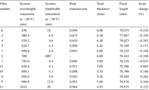
1Hzimagingsupportedforexposures <500ms;2sforreposition;13stotalInstrumentfunctional testing <2km/pixelspatialsampling<2km/pixelduringflyby,fromorbittofill gapsinflybycoverage2km/pixelresolutionat4.5planetradii,or within10,000kmduringorbitGeometriccalibration, trajectoryanalysis Spectralfiltersformappingofolivine, pyroxene,glass,opaques7WACspectralfilters,violetto1050nm11WACspectralfilterstomeasurekey features,plusclearfilterRadiometric calibration Mapabundancevariationsinopaque andmaficminerals:750/415nm, 750/650nm,and750/950nmratios measuredto1%precision
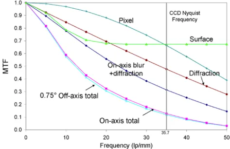
MTF>0.62at1cycle/8pixelstopreserve variationsabovenoiselevelMTF∼0.751cycle/8pixelsfortypicalfilterAnalysisand radiometric calibration Modeldarkcurrenttosystemnoise (1DN)Darkcurrentmodelresidualsatread-noise levelat<5°C,consistentwithmodel accuracynoise
Radiometric calibration Responselinearityto1%Departuresof≤2%atlowDNlevels correctableduringgroundprocessingRadiometric calibration Characterizeresponsivityto5%absolute, 2%relativebetweenfiltersOn-groundcalibrationat−34,−30,+24°C insufficientforinterpolationtohigher (−10°C)CCDoperatingtemperatures;need flightmeasurementofMercury-illuminated calibrationtarget Radiometric calibration Modelflatfieldto0.1%precision(0.4of noiseatfullwell)Compositeof100imagesprovides0.04% precision;flightmeasurementsneededdue tomobilityofdustdonuts
Radiometric calibration Protectopticsfromcontaminationthat increasesscatteredlightStowMDISinpositionwithoptics protectedfromcontaminantsduringburns, thermalspikesonsunshade
FrontopticstowableininstrumentbaseInstrumentfunctional test Underlineditemsincuradditionaldataprocessingorrevisionstothedataacquisitionstrategytomeetrequirements,asindicated
Table4dMDISrequirementsandas-builtperformanceforhigh-resolutionandstereoimaging Measurement objectiveMeasurementrequirementInstrument/spacecraftrequirementAs-builtperformanceMethodofverification Targeted high-resolution imaging Acquirecontinuousstripof imageswithNACfrom minimumorbitalaltitude
Atminimumaltitudeof200km,NAfootprint moves1FOVin1.4s.Requires1Hzimaging.1Hzimagingsupportedusing2×2 pixelbinningorquarterframesInstrumentfunctional testing Acquire<20m/pixelNAC framesfromlowestaltitude expectedoverdayside (280km)with<20msmear duetospacecraftmotion NACIFOV<71µradNACIFOV20µradGeometricand radiometriccalibrationMinimizetimeforCCDframetransfer (minimumusefulexposuretime∼2×frame transfertime)
3.7msframetransferyields∼7ms exposure.At3.3km/s,18mlinear smear.Pixelfootprint12m/pixelafter 2×2binningrequiredfor1Hzimaging Nosaturationatminimum exposuretimeNosaturationin7msNACimageat33°phase, minimumsolardistance,2×2pixelbinningWorst-casesaturationtime16msRadiometriccalibration andphotometricmodel Off-nadirimagingto complementnadir geometryforstereo
Imageareasbothatnadirand off-nadirwithsimilarlightingConsistentobservationstrategymeetingother spacecraftconstraintsNhemispherenadirfirstsolarday, off-nadirsecondsolarday; Shemispherenadirandoff-nadiron adjacentorbitsfirstsolarday.Meets spacecraftconstraintsasgivenin Table4b.
Coveragesimulation Abilitytotakeoff-nadir imagesanarbitraryorbitPivotandspacecraftrollusabletogetherto pointMDISboresightoffsetalong-trackfrom localnadir
Rollspacecrafttokeepnadiroffset frompivotplane,supplyMDISwith pivotattitude
Spacecraftfunctional testing Stereoverticalaccuracygoal is±2kmfrom6000-km altitude(rootsumsquared pointingknowledge240µrad)
180µradboresightknowledgewithin-flight calibrations(1.4×worsethanNEARwith in-flightpointingcals.usingstarimages; allowsforscanplanevs.fixedpointing) Abilitytoextractmultiple subframesfromstarfield imagesforpointing calibrationswithin downlink 200µrad expected pointing knowledge Instrumentand spacecraftfunctional testing;flight calibrationrequiredfor pointingknowledge
Table4d(Continued) Measurement objectiveMeasurementrequirementInstrument/spacecraftrequirementAs-builtperformanceMethodofverification 150µradknowledgeofpivotposition85µradPivotposition calibration KnowledgeofcenterofMDISexposureto ±10ms<1msuncertaintyAnalysisofimage acquisitiontiming usingexternalstrobe andUniversalTime clock Acquireimagesfromorbitswithminimal thermaldisturbancestoinstrumentdeckNadirandoff-nadir coverageplannedfrom near-terminatororbitwith lesserthermalvariation
Bydesign
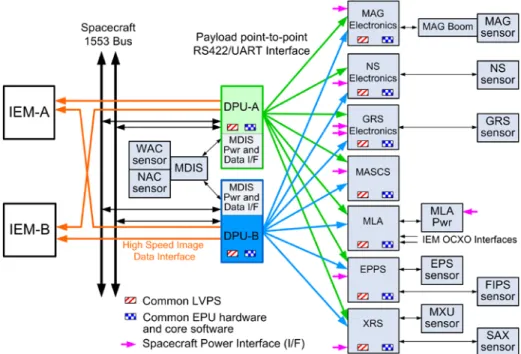
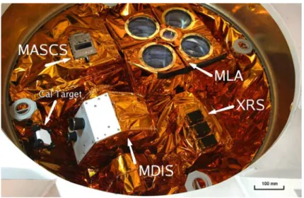
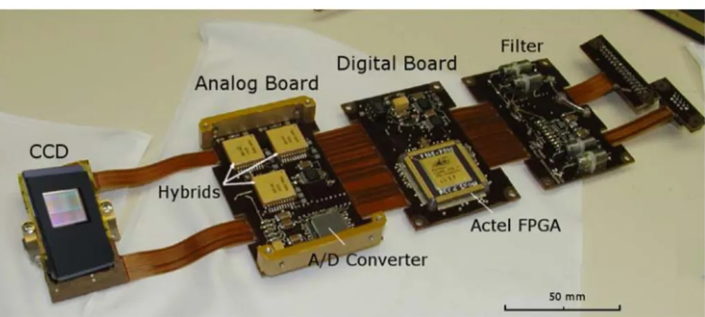
Fig. 1 Photograph of the Mercury Dual Imaging System (MDIS) instrument just prior to integration with the spacecraft (S/C). Redundant Data Processing Units (DPUs, not shown) connect to MDIS through the DPU Interface Switching Electronics (DISE). Red-tag covers were used to protect apertures during handling and were removed before flight.
Some thermal blankets are not shown to reveal structure
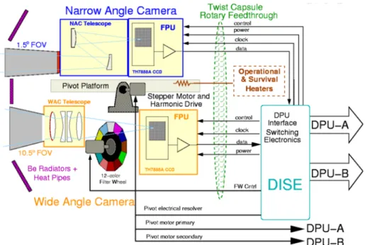
the dual cameras of MDIS are able to pivot about a common axis (Fig.1). The nominal operational scan range of the platform is 40° in the sunward direction and 50° anti-sunward.
With spacecraft slewing, phase angle coverage of 26°–142° is possible in both cameras at the center of each field of view (FOV). Imaging is available in the WAC 5.3° farther in each direction because of the wide FOV; in the NAC imaging is possible 0.75° farther. During launch and key orbital maneuvers, the camera can be placed in a stowed position, providing contamination protection for the optics (Fig.2).
The thermal environment poses challenges for MDIS performance, because the cameras must view the hot surface (>400°C) on some orbits for∼120 minutes. Although this ther- mal environment presents issues for all parts of the instrument, the most stressing case is maintaining nominal temperature of the charge-coupled device (CCD). Wide swings in de- tector temperature potentially degrade signal-to-noise ratio (SNR), calibration accuracy, and the value of the acquired images.
The thermal environment also poses a challenge for stereo imaging. Stereo provides mea- surement of both relief (the elevation difference between stereo resolution cells, about 5×5 to 7×7 pixels in size) and elevation relative to mean planetary radius. In the southern hemi- sphere, beyond the range of the MLA, the primary knowledge of elevation to mean planetary radius will be from photogrammetric analysis of MDIS images (plus occultations of radio signals from the spacecraft to Earth). Accuracy in an elevation determination from stereo is proportional tohσ/tan(e), wherehis the orbital altitude,σ is the uncertainty in pointing knowledge between image pairs, ande is the emission angle of the off-nadir image. The goal for elevation accuracy is±2 km. Assuming that accuracy can be improved by a factor of two using photogrammetric techniques at the corners of four stereo pairs, the required accuracy is±4 km. For a 6,000-km orbital altitude, which is appropriate to southern high latitudes, and a 25° emission angle of the off-nadir images, the required pointing knowledge is±240 µrad. This requirement is budgeted between uncertainty in the knowledge of im- age acquisition time (which translates into downtrack position error), uncertainty in pivot
Fig. 2 Range of motion of the MDIS pivot platform. Operational range is−40° sunward to+50° antisun- ward (planetward). When stowed, the sensitive first optic of each telescope is protected
position within its plane of motion, and variation in orientation of the pivot plane relative to thermal distortion of the spacecraft. The largest term is due to variation in pivot plane orientation relative to the star camera (Table4d). On the Near Earth Asteroid Rendezvous (NEAR) mission, orientation of its fixed-pointed camera was modeled to±130 µrad as a function of temperature of the spacecraft structure, using star-field images to calibrate pointing. Allowing for the fact that MDIS moves in a plane, and that the plane may shift in orientation with temperature, the budget is increased by√
2 to 180 µrad, leaving 140 µrad for uncertainty in position within the pivot plane and along-track errors. To facilitate pointing