It is hereby confirmed that the thesis entitled 'Control of Autonomous Underwater Vehicles' submitted by Mahendra Pratap Singh and Bilas Chowdhury in partial fulfillment of the requirements for the award of Bachelor of Technology Degree in Electrical Engineering from National Institute of Technology, Rourkela is an authentic work done by them under my supervision. To the best of my knowledge, the matter contained in this thesis has not been submitted to any other university/institute for the award of a degree or diploma. BD Subudhi for initiating this project and also for his expert insight and assistance in the.
A two-loop controller (PI control) is used to control the pitch and consequently the depth of the AUV. An obstacle avoidance scheme using pitch and depth control is also used to avoid static obstacles in the path of the AUV. The thesis presents and discusses the results of the above three control objectives, such as AUV tracking control, obstacle avoidance controller and formation control of multiple AUVs.
About 70% of the earth's surface is covered with water which is like an empire of natural resources. The first AUVs were built in the 1970s, put into commercial use in the 1990s, and today are mostly used for scientific, commercial and military mapping and surveying tasks (Blidberg2001).
AUV in India
Objectives
Organization of thesis
Autonomous Underwater Vehicle
The first AUV was developed at the Applied Physics Laboratory at the University of Washington as early as 1957 by Stan Murphy, Bob Francois and later Terry Ewart.
Applications of AUVs
The Special Purpose Underwater Research Vehicle, or SPURV, was used to study the diffusion, acoustic transmission and wakes of submarines.
AUV Technology
AUVs are also used in anti-submarine warfare, to help detect manned submarines. Aluminum/oxygen "semi-cell" technology to allow an AUV to pass under the Arctic ice. In the past few years, many AUVs have made use of Global Positioning Systems (GPS).
Sensors: An AUV is simply a platform that you can mount sensors on to get data from. Recently, it has been realized that we need to develop completely new sensors based on the limitations imposed by AUVs, i.e. Other technologies are also used, such as short-range laser communication and relatively noiseless communication over longer distances using RF field current density.
There has been a significant advance in acoustic communication, so that communication with a relatively low error rate is possible over ranges of kms at a bit rate of a few kbps.
Main components of AUV
The pressure hull provides most of the vehicle's buoyancy and space for dry components such as batteries and control electronics [4]. The tail cone resembles a torpedo tail and is designed to reduce drag caused by the pressure drop at the bottom. end of the vehicle body. The main body includes electronic circuits, batteries, Rate GYRO which is used to measure speed. Rudder is the vertical and movable control surface, which is hinged to the fin and mainly controls the yaw motion of the vehicle.
![Fig. 2.2: Exploded view of AUV. [22]](https://thumb-ap.123doks.com/thumbv2/azpdfnet/10558367.0/19.918.129.777.408.836/fig-2-2-exploded-view-of-auv-22.webp)
AUV Sensors
Modeling
Kinematics which relates only geometric aspects of motion, and Dynamics which is the analysis of forces that cause motion. Because six independent coordinates are needed to determine the position and orientation of a rigid body, AUV has six degrees of freedom (6 DOF). The first three coordinates and their time derivatives are used to represent the position and translational motion along x, y, and z axes, while the last three coordinates and their time derivatives are used to describe the orientation and rotational motion.
For the analysis of the vehicle movement in 6DOF, we choose two coordinate frames. The moving reference frame is attached to the vehicle called a body-fixed reference frame. For marine vessels, it is usually assumed that the acceleration of a point on the Earth's surface can be neglected.
This indicates that the linear and angular velocities of the vehicle must be expressed in body-fixed frame, while position and orientation must be described with respect to inertial frame. In a very general form, the movement of vehicle in 6DOF can be described by the following vectors:. Where describes the position and orientation of the vehicle with respect to the ground-fixed reference frame, the translational and rotational velocities with respect to the body-fixed reference frame, and the total forces and moments acting on the vehicle with respect to the body-fixed reference frame.
The body-fixed angular vector 2 and the Euler velocity vector are connected via the transformation matrix J2 2) by the relation.
![Table 3.1: Notation used for AUV modeling. [8]](https://thumb-ap.123doks.com/thumbv2/azpdfnet/10558367.0/23.918.98.821.397.885/table-3-1-notation-used-auv-modeling-8.webp)
Dynamics
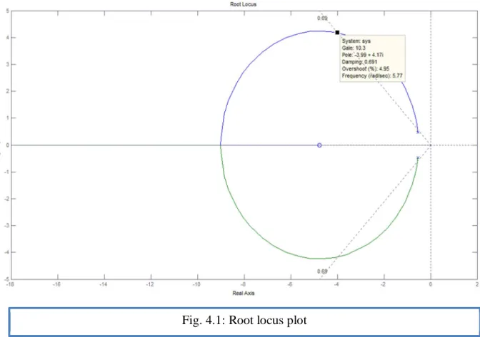
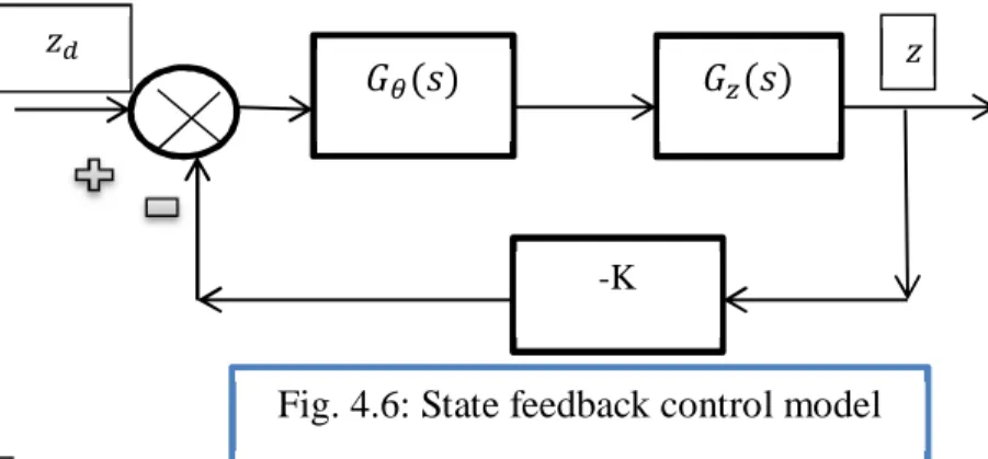
Pitch and Depth Control
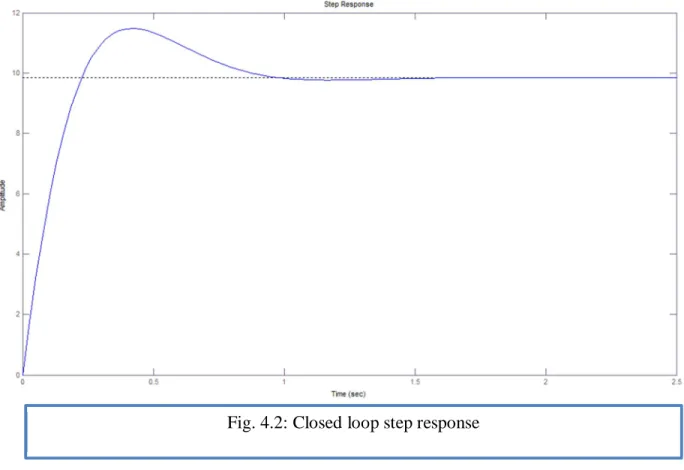
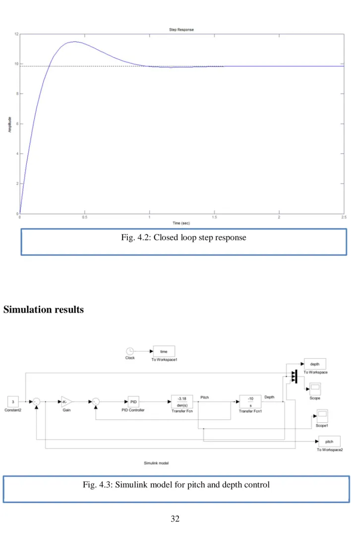
The inner loop controller, the PD controller controls the pitch and the outer loop controller, the P controller controls the depth of the vehicle.
Linearized kinematics and dynamics
Tracking and Formation Control
Advantages of formation control
Approach
In this chapter, the problem of leader-follower formation control for multiple autonomous underwater vehicles (AUVs) in spatial motion is addressed. The goal is to drive a leader robot along a desired path and have the follower robots maintain a desired formation in relation to the leader's configuration in 3-dimensional space. The theoretical formalization and mathematical analysis of this approach is difficult, and therefore it is not easy to guarantee the convergence of the formation to a desired conguration.
The virtual structure approach considers the robot formation as a single virtual rigid structure, so that the behavior of the robot system can be assimilated to that of a physical object. Desired trajectories are for the entire formation as a whole and not assigned to each individual robot. In this case, the behavior of the robot formation is predictable and the control of the robot formation is therefore straightforward.
In the leader-follower approach, one robot of the formation, designated as the leader, moves along a predetermined trajectory while the other robots, the followers, must maintain a desired distance and orientation relative to the leader. Since the bandwidth of underwater acoustic communication is very limited, which prevents a large number of data exchanges between vehicles, the leader-follower scheme is useful because the only communication event required is the transmission of the necessary leader information. to the follower. In leader-follower formation control, the AUV leader must track the desired trajectory and. the follower AUV tries to maintain a desired distance and angle relative to the leader.
The leader-follower formation problem in the horizontal plane can be given as follows: Given the position of the lead vehicle, the reference trajectory for the follower is set in such a way that its position is shifted by a distance d and an angle with respect to leader. The orientation of the vehicle is described by the angle measured from the inertial axis X and r is the rate of turn (angular). The variable indicates the control force along the vehicle's upward motion, and the variable indicates the control force along the vehicle's forward motion.
The constants and are the combined rigid body and the added mass terms, and are the combined rigid body and the added moment of inertia about the zb axis. The reference path for the following AUV is the circle with the same frequency but with a different radius. The leader AUV follows its desired trajectory which is a circle with a radius of 8m and also the follower AUV maintains a constant distance of 2m from the leader AUV.
![Fig. 5.1: AUV diagram showing inertial and body fixed frames. [15]](https://thumb-ap.123doks.com/thumbv2/azpdfnet/10558367.0/40.918.133.782.405.754/fig-auv-diagram-showing-inertial-body-fixed-frames.webp)
Leader follower formation control of AUVs in 3D
Obstacle Avoidance
To successfully avoid this traffic, obstacle avoidance systems have been built into AUVs so that they can easily pass obstacles without damage while continuing their mission (e.g. monitoring). This chapter uses an obstacle avoidance scheme based on AUV's pitch and depth control. This can be achieved by increasing the angle of inclination of AUV so that the depth (height) above the seabed increases or decreases, i.e.
To avoid obstruction, four conditions namely heave, pitch speed, pitch angle and depth are considered in contrast to the pitch and depth control where heave was not considered. The important aspect is to plan a new path that will be traversed by the vehicle and then make a controller that will execute this planned path. Now a new path must be calculated so that the vehicle does not hit the obstacle.
Thus, first the AUV will rise up to the height of the obstacle while maintaining a certain distance from the obstacle. After reaching the top of the obstacle, the AUV moves over the top to a safe height and when the downslope part is encountered, it descends and moves towards the bottom of the obstacle. When the obstacle is passed, the obstacle avoidance algorithm ends and the AUV returns to the previous path.
Simulation results
Appendix
5] http://en.wikipedia.org/wiki/Autonomous_underwater_vehicle [6] http://robotics.ee.uwa.edu.au/auv/usal.html.
![Fig. 2.1: REMUS AUV [image courtesy of AUV fest 2008: Partnership runs deep Navy/NOAA, oceanexplorer.noaa.gov]](https://thumb-ap.123doks.com/thumbv2/azpdfnet/10558367.0/16.918.472.842.718.1056/fig-remus-image-courtesy-partnership-navy-noaa-oceanexplorer.webp)
![Fig. 3.1: Body-fixed and inertial reference frames. [9]](https://thumb-ap.123doks.com/thumbv2/azpdfnet/10558367.0/24.918.108.812.449.1106/fig-3-1-body-fixed-inertial-reference-frames.webp)