1
CHAPTER 1 INTRODUCTION
First chapter of this proposal will discuss about the introduction to this project, covered with background of study, problem statement, objective, scope of study and the reasons that lead to the implementation of this evaluation project.
1.1 Background of study.
This study is focusing on an automotive engine heat management system. The current automotive engine heat management is only working on controlling the engine temperature for initial startup and maintaining the temperature of its ideal running temperature that is handled by thermostat.
A typical automotive engine operates by burning fuel in the combustion chamber to move the piston cylinders. This cycle producing waste heat that must be absorbed by automotive cooling system. The basic components of cooling system are radiator, coolant which are usually combination of water, coolant (to improve heat absorption efficiency) , ethylene glycol (antifreeze), pressure cap, reserve tank, water pump and thermostat. The mixed liquid coolant is sent through passages in the engine block and head. As its circulating through the passages, it absorbs the heat from the engine. The heated liquid then flows to the radiator that is normally placed in front of engine compartment through rubber hose on the top of radiator. Inside the radiator the heated coolant will flow through several tubes. These tubes were arranged alternating with the cooling fins that are combination of zigzagged and flattened aluminum strips. The heat will then be transfer to the fins and will be cooled down as stream of air flow through the fin. The cooled liquid is then returned into the engine block through the rubber hose
2
at the bottom of the radiator to continue the cycle of absorbing heat to cool down the engine. A typical radiator will be connected to a reserve water tank with a small rubber hose. This tank was placed either side in the engine compartment. This reserve tank will be used to store the released coolant fluid from the radiator and this fluid would then return to the cooling system after the engine cooled down. This cooling system was used to prevent the engine from overheating. Once the engine overheats, the consequences are the piston scuffing, rapid expansion of aluminum head, the crushing head gasket which leads to gasket failure and leaking of coolant or combustion gas into the combustion chamber or the coolant passage, cam scuffing, seizure, breakage and finally the permanent damage to the engine. Due to severe damage caused by overheating problem, the total repairing cost would be expensive.
Hence this project is actually aiming for a system that will provide some time for consumers to seek help and stop the vehicle in a safe place by delaying engine overheat other than to save the engine from suffering overheat. This system is also aided by the visual panel to signal to consumers as well as guidance on the engine situation. This system is basically working on the concept of evaporative cooler.
Use of this concept with the help of some tools taking into account economic factors can produce high beneficial effects compared with the investment made especially in emergency situation when the car engine temperature rise rapidly and overheat. This system aims to avoid damage to the engine and provide better safety guarantees to the consumer
1.2 Problem Statement
1.2.1 Problem Identification
Cooling system is one of the most important systems for each vehicle engine.
However, this cooling system is often associated with many problems that result brings a great harm that is over heat. This problem will have a big impact, such as permanent damage to the engine and expensive to repair. So this project should solve these three problems.
3
1) Help to maintain the engine temperature at safe range running temperature.
2) Give a warning and notify the user about the current condition of their engine’s temperature.
3) Shutdown the engine if the temperature keeps increasing towards overheats.
1.2.2 Significant of the project
By using this system is assisted by a visual guidance system to provide early warning to consumers about the state of their vehicle engine if it is in dangerous situation. This warning system will give consumers the opportunity to act whether to stop the vehicle in a safe place or to find workshops nearby. In the meantime the SHMS itself will take a precaution steps to avoid the engine from overheat through series of action. This project will also give an improvement in automotive industry in providing more reliable vehicle in future.
1.3 Objective and Scope of Study 1.3.1 Objective
The main objective of this project is to develop Smart Heat Management System (SHMS) that is PnP (plug and play) basis to prevent the engine from overheat by solving the associated problem that may lead to overheat.
1.3.2 Scope of Study
This project will create a system to monitor continuously the temperature of the vehicle engine and will display the current engine condition. The system will warn the users if their vehicles engine in danger and leading to overheat problem. If the engine leading to overheat, the system will warn the user and in the meantime trying to delay the engine from overheat by communicating with mist spray to spray a thin layer of water particles onto the radiator. The thin water layer sprayed onto the radiator will
4
evaporated as air flow through. This evaporation cooler is almost similar on how sweat cooling and maintaining our body temperature. The concept will be use to cool down the engine temperature at greater scale to prevent the temperature from keep increasing while giving the user and extra time to pull over their vehicle in safer place or nearby workshop
1.4 Relevancy of the project
All of the vehicles with engine will require the cooling system to continue working. The engine is much dependent on the cooling system and it will be worse if this cooling system fail. The failures of cooling system will also damaging the engine component and will cause a permanent damage to the engine besides could endanger the user if this situation happen. This system will help to delay the engine temperature from keep increasing before having an overheat problem by cooling down the radiator using the evaporation cooling concept which helped by a pump that will pump the water through mist sprinkler and will spread a thin layer of water particle onto the radiator.
The air stream passed through the radiator will evaporate the thin layer of water as well as cooling down the radiator and the coolant fluid. This concept is similar to how sweating process cooling down and maintaining our body temperature. The project are about to optimize the system to fit the application while doing some relation and calculation to relate the entire variable into an equation.
1.5 Feasibility of the project
Two semesters is the time given to complete this project. This includes research, development, improvement and discussion. There will be several tests to record the efficiency data of the system and also to optimize the system to its best possibilities. The availability of hardware such as pump, sprinkler, thermostat switch and all related material make this project can be done without any delayed. Based on the availability of hardware, with tight schedule it is very clear that this project is feasible to be completed within the time frame assign by FYP coordinator.
5
CHAPTER 2
LITERATURE REVIEW
This chapter discusses about the theories and paperwork reviews related to this project.
The first step of this project was to gather information on existing radiator designs and general heat exchangers. After gathering information, we gained a thorough
understanding of how a radiator works, the current radiator designs and all the possibilities that may lead into overheat.
2.1 Theory
2.1.1 Heat Exchangers
A steady-state heat exchanger consists of a fluid flowing through a pipe or system of pipes, where heat is transferred from one fluid to another. Heat exchangers are very common in everyday life and can be found almost anywhere (Sonntag, et al.
2003).Some common examples of heat exchangers are air conditioners, automobile radiators, and a hot water heater. A schematic of a simple heat exchanger is shown in Figure below.
Figure 2.1 : Cross Flow Heat Exchanger ( Yunus A Cengel, 2006 )
6 2.1.2 Automobile Radiators
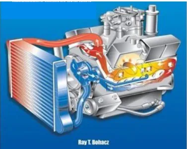
Almost all automobiles in the market today have a type of heat exchanger called a radiator. The radiator is part of the cooling system of the engine as shown in igure below. As you can see in the figure, the radiator is just one of the many components of the complex cooling system.
Figure 2.2 Automotive Cooling System (Ray T. Bohacz, 2007).
Most commonly made out of aluminum, automobile radiators utilize a cross-flow heat exchanger design. The two working fluids are generally air and coolant (50-50 mix of water and ethylene glycol). As the air flows through the radiator, the heat is transferred from the coolant to the air. The purpose of the air is to remove heat from the coolant, which causes the coolant to exit the radiator at a lower temperature than it entered at. The benchmark for heat transfer of current radiators is 140 kW of heat at an inlet temperature of 95 °C. The basic radiator has a width of 0.5-0.6 m (20-23“), a height of 0.4-0.7 m (16-27”), and a depth of 0.025-0.038 m (1-1.5”). These dimensions vary depending on the make and model of the automobile.
7 2. 2 Analogy Of Heat Transfer In Radiator
Below is the simplified diagram to explain on how the heat transfer occurs in the radiator component. Ta and Tb indicate the inlet and outlet temperature of the cooling water.
Figure 2.3: Heat Transfer Analogy ( Yunus A Cengel, 2006 )
Here, Arrow A represent the heat is transferred by convection from the radiator fin to the air stream. Arrow B represent the heat is transferred by conduction from the tube to the fin while Arrow C represent the heat is transferred by convection from the hot water flow to the tube surface.
2.3 Mechanism of Natural Convection
We know that a hot boiled egg on a plate eventually cools to the surrounding air temperature. The egg is cooled by transferring heat by convection to the air and by radiation to the surrounding surfaces.
As soon as the hot egg is exposed to cooler air the temperature of the outer surface of the egg shell drops somewhat, and the temperature of the air adjacent to the
W
inW
out8
shell rises as the result of the heat conduction from the shell to the air. Consequently, the egg is surrounded by a thin layer of warmer air, and heat is then transferred from this warmer layer to the outer layer of air. The cooling process in this case is rather slow since the egg would always be blanketed by warm air, and it has no direct contact with the cooler air farther away. We may not notice any air motion in the vicinity of the egg, but careful measurements would indicate otherwise.
The temperature of the air adjacent to the egg is higher and thus its density is lower, since at the constant pressure the density of egg is inversely proportional to its temperature. Thus we have situation in which some low density or “light” gas is surrounded by a high density or “heavy” gas, and the natural gas dictates that the light gas rise. This phenomenon is characterized incorrectly by the phrase “heat rise” which is understood to mean “heated air rise”. The space vacated by the warmer air in the vicinity of the egg is replaced by the cooler air nearby, and the presence of cooler air in the vicinity of the egg speeds up the cooling process. The rise of warmer air and the flow of cooler air into its place continue until the egg is cooled to the temperature of the surrounding air. The motion that results from continual replacement of the heated air in the vicinity of the egg by the cooler air nearby is called a natural convection current, and the heat transfer that is enhanced as a result of this natural convection current is called natural convection heat transfer. ( Yunus A Cengel, 2006 )
2.4 Convection on Radiator Surface
The similar concept applied to the radiator and instead of the egg that was used as an example above it is replaced by radiator fin that was made to increase the surface for better heat transfer and was proved by this simple equation (Q = hA∆T). Area of the surface that is exposed to heat transfer is indicating as “A” and proportional to the heat transfer rate, Q. The convection process happened to the egg are the same happened to the radiator fins if the car is not moving and the fan is not rotates. If the car is on moving or the radiator fan is rotates, the air stream is forced to flow through the radiator fins and carry the heat away. This is called forced convection. The heated air is replaced by
9
cooler air with faster rate in forced convection rather than natural convection.
( S. Mostafa Ghiaasiaan, 2011)
2.5 Evaporative Heat Transfer
Moisture content also affects the effective conductivity of porous mediums such as soils, building materials and insulations, and thus heat transfer through them. Several studies have indicated that heat transfer increases almost linearly with moisture content, at a rate of 3 to 5 percent for each percent increase in moisture content by volume.
Insulation with 5 percent moisture content by volume, for example, increases heat transfer by 15 to 25 percent relative to dry insulation. (ASHRAE Handbook of Fundamentals, 1993)
Atmospheric air can be viewed as a mixture of dry air and water vapor, and the atmospheric pressure is the sum of the pressure of dry air and the pressure of water vapor, which is called the vapor pressure Pv. Air can hold a certain amount of moisture only and the ratio of the actual amount of moisture in the air at a given temperature to the maximum amount air can hold at that temperature is called the relative humidity φ.
The relative humidity ranges from 0 for dry air to 100 percent for saturated vapor in saturated air (air that cannot hold any more moisture). The partial pressure of water vapor in saturated air is called saturation pressure Psat.
The amount of moisture in the air is completely specified by the temperature and the relative humidity, and the vapor pressure is related to relative humidity by
Pv= φPsat
10
CHAPTER 3 METHODOLOGY
This chapter discusses about how the project would be carried out. It includes the method of research, tools, components, and software involved.
First of all, the project start with gathering all of the information about automotive cooling system, the problem associated with cooling system, all the causes and sign that will lead to overheat problem, study in details of each equipment associated with cooling system including the equipments specification and all the cooling system design available in automotive industry. All of this information will be useful to comply with project objective.
The next initial step is to recover all the related equation that may involve in the designing stage especially on heat transfer equation. All the theory will be kept for further reference and for modification to suit the new design. Then next is creating and drafting all the conceptual design to meet the objective to prevent the engine overheat problem. The drafts are including the action system, controlling system and display system. All the conceptual design will be then tested to eliminate all the possible causes that may lead to overheat problem. All the passed conceptual design will be brought to next stage where all the related component for each conceptual design will be analyzed theoretically for effectiveness and economic factor.
The best conceptual design will move to fabrication process. After the completion of fabrication, the system will be tested for several times to collect all the related data and variables to be analyzed for system optimization. The optimizations are including the material and easiness of fabrication, the cost reduction and also efficiency
11
improvement. The system will also be tested under several conditions to test the system durability, estimation for life span and suitability for all engines available on the market.
3.1 Project Activity
Literature review and information gathering
All information involved being collected, obtained through article, book, journal paper and World Wide Web.
Drafting of conceptual design
After understanding the main operation of current cooling system and problem associated, the system will be draft to meet the main objective.
Analyze the conceptual design
Using all the drafted conceptual design, each of the design will be analyzed theoretically according to the equation and calculation.
Selection of the best conceptual design
The best conceptual design will be judge according to several criteria including the efficiency economic factor.
Fabrication of conceptual design
The preparation for fabrication including raw material and process procedures will be made. Each equipment will be assembly to build a complete system
Experiment and data collection
The system will be go into series of experiment under several condition to collect the related data and variables for system optimization.
Discussion and Conclusion System optimization
The system will be optimize for several criteria such as efficiency, economic factor and suitability for the all engine available on the market.
12 3.2 Mathematical Model
This mathematical model is to relate the theoretical assumption to the equation related for clearer understanding. This mathematical model is the manipulation of the existed heat transfer equation and analogy to be fitted into this project condition and requirements according to the known variables.
3.2.1 Case Study 1
During a hot sunny day, a car was driven at speed of 80km/h and expected to have a problem with the engine cooling system. The car was equipped with SHMS and after reaching 1050C that is preset temperature in SHMS, the system is activated and forcing the engine to cool down as fast as possible to avoid further temperature increment that will cause the engine over heat. The environment conditions are 1 atm, 35oC and 40 percent relative humidity. Justify with calculation whether the SHMS will success or fail to avoid the engine from overheat.
Solution
The SHMS will spray a layer of water film onto the hot radiator to cool down the radiator and then the pump will circulate the cooled cooling fluid through the engine to reduce the engine temperature.
Assumptions
1. The low mass flux conditions exist so that the Chilton-Colburn analogy between heat and mass transfer is applicable since the mass fraction of vapor in air is low.
2. Both air and water vapor at specified conditions are ideal gases.
3. Radiation effects are negligible.
4. 80km/h to m/s = 23m/s Properties
Because of low mass flux conditions, we can use dry air properties for the mixture at the average temperature of (T∞ + Ts)/2 which cannot be determined at this point because of the unknown surface temperature Ts. We know that Ts > T∞ and, for the purpose of
13
property evaluation, we take Ts to be 45 oC and the properties of dry air at the average temperature of 40 oC and 1atm are (Table A-9 and A-15, attached at last section)
Water: hfg = 2407kJ/kg, Pv = 7.38 kPa ; also Pv = 5.63 kPa at 35 oC Dry air: cp = 1.007 kJ/kg oC, α = 2.346 x 10⁻⁵ m2/s
The molar masses of water and air are 18 and 29 kg/kmol, respectively (Table A-1).Also the mass diffusivity of water vapor in the air at 40 oC is DH2O-air = 2.77 x 10⁻⁵ m2/s (Table below)
Analysis
Utilizing the Chilton-Colburn analogy, the surface temperature of the radiator can be determined
Ts = T∞ -
T∞ = Surroundingtemperature (0C) Ts = Surface Temperature (0C) Where the Lewis number is
Note that we can take the Lewis number to be 1 for simplicity, but we chose to incorporate it for better accuracy.
14
The air at the surface is saturated, and thus the vapor pressure at the surface is simply the saturation pressure of water at the surface temperature (7.38 kPa). The vapor pressure of the air away from the surface is
Pv,∞ = φPsat @ T∞ = (0.40) Psat @ 35 =(0.40)( 5.63 kPa) = 2.252 kPa
Psat = Saturation Pressure, kPa
Noting that the atmospheric pressure is 1 atm = 101.3 kPa, substituting gives
Ts = 1050C -
= 1050C – 83.90C
= 21.10C
Ts = Surface Temperature, (0C) Discussion
Therefore, the temperature of the radiator surface can be lowered up to 21.1 0C by this process. Even though, the temperature will not reach to that temperature in real application and also will not remain constant since there are always heat builds up when the engine is running. This mathematical model showing that the radiator and engine are possible to be cooled down using this process and the huge temperature difference will make the engine is able to run at safe temperature. So, the SHMS is basically successfully preventing the engine from over heat.
15 3.2.2 Case Study 2
During a hot sunny day, a car was driven at speed of 80km/h and expected to have a problem with the engine cooling system. The car was equipped with SHMS and after reaching 1050C that is preset temperature in SHMS, the system is activated and forcing the engine to cool down as fast as possible to avoid further temperature increment that will cause the engine over heat. The environment conditions are 1 atm, 35oC and 40 percent relative humidity. The SHMS are operating for 10 minutes to cool down the engine. The radiator dimensions are 0.6m height and 0.7m width. The rate of diffusivity water into air at 35 oC is
Determine the heat transfer coefficient under same flow conditions.
Solutions
Air blown over a body covered with a layer of water, and the rate of heat transfer coefficient under same flow conditions over same geometry conditions is to be determined. The surface area of the radiator As = 0.42 m2.
Assumptions
1. The low mass flux conditions exist conditions exist so the Chilton-Colburn analogy between heat and mass transfer is applicable (will be verified).
2. 80km/h to m/s = 23m/s 3. The
Properties
The molar masses of water and air are 18 and 29 kg/kmol, respectively (Table A- 1).Because of low mass flux conditions, we can use dry air properties for the mixture at the 35 oC and 1 atm. The properties of dry air at the temperature of 35oC and 1atm are (Table A-15, attached at last section)
16
Dry air @ 35 oC: ρair = 1.145kg/m3, cp = 1.007 kJ/kg oC, α = 2.277 x 10⁻⁵ m2/s
Analysis
The incoming surface temperature at the hot radiator is higher than the temperature at free stream air temperature. So we assume the surface temperature at 40oC and the vapor pressure of water at this temperature is 7.384 kPa, its mass fraction at the surface is determined to be
WA,s = (
) (
)
WA,s = Mass fraction of the water at the surface
This confirms that the low mass flux approximation is valid. The mass fraction of water in free stream air that is at 35oC is determined to be
WA,∞ = (
) (
)
WA,∞ = Mass fraction of the water at the surface The rate of evaporation of water in this case is
̇
̇
Then the mass convection coefficient becomes
̇
( )
17
Using the analogy the heat and mass transfer, the average heat transfer coefficient is determined from
(
) (
)
Discussion
Based on the calculation, by using the radiator with surface area of 0.42m2 with the surface area assumed to be 40oC and the free stream air at 35 oC. When the layer of water sprayed onto the radiator surface the rate of heat transfer are about .For information, our body transfer the heat about when sweating for a normal man.
18 3.3 Preliminary Research
3.3.1 Thermostat Switch
Figure 3.1: Thermostat switches
A thermostat is the component of a control system which regulates the temperature of a system so that the system's temperature is maintained near a desired set point temperature. The name is derived from the Greek words thermos "hot" and statos
"a standing". The thermostat does this by switching heating or cooling devices on or off, or regulating the flow of a heat transfer fluid as needed, to maintain the correct temperature.
In this project two thermostat switches will act as on or off devices that will be responsible to measure the temperature of cylinder head temperature and sending the signal to the controller circuit board to be analyzed for the further response. Thermostat switch 1 was set at 95°C and 100°C for thermostat switch 2. These two thermostat switches were normally closed and will be open at the determined temperature.
When the cylinder head temperature reached 95°C, which mean the engine is having problem with the cooling system. The temperature switch 1 will be activated and sending the signal to the controller circuit board. The circuit board will display the warning on the display panel and in the meantime triggering the pump to pump the water through the sprinkler to spray a water mist to create a thin layer of water onto radiator surface. As the air stream flow through the radiator, the evaporation cooling concept will take place to help the radiator cooling faster at greater rate of heat transfer to reduce the
19
engine temperature. In the meantime, the driver will be given an extra time to pull over the car at the safer place or nearby workshop.
If the temperature still rising until reached 100°C, the thermostat switch 2 will activated and sending the signal to the controller circuit board. The circuit board will then sending the signal to the display panel informing the driver the engine will be force to turn off in several minutes. Then the counter will start to count to zero and engine will be turned off.
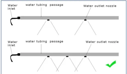
3.3.2 Mist Spray System
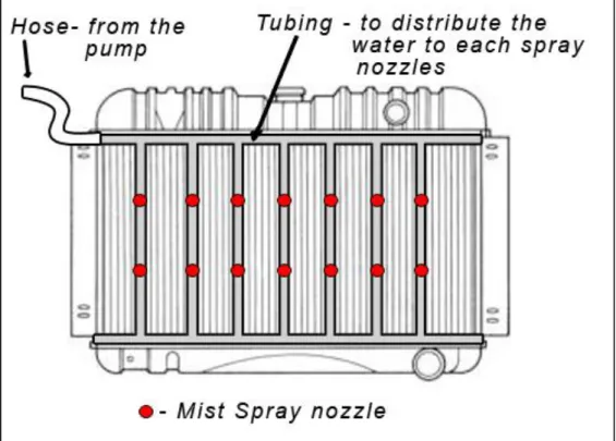
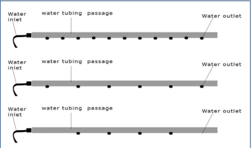
Figure 3.2: Spray Nozzles Arrangement.
The mist spray system contains several parts that are spray nozzle, aluminum tubing, water pump, water reservoir and rubber hose. All of these parts were attached to each other to build a complete mist spray system (MSS). This MSS begin with a high
20
pressure pump and a spray nozzle designed to produce tiny water droplets that will spray onto the radiator to help cooling down the radiator and coolant liquid as they flash evaporate. Performance is enhanced by increasing the number of nozzles used and adjusting the water pressure.
When the pump was triggered by the controller circuit board, the pump will start pumping the water from the water reservoir tank. The water will flow into the hose and distributed in each aluminum tube in front of the radiator. The water will be forced to go out through each tiny hole of spray nozzles around 5 to 10 microns. These tiny holes will force the water to flow out as a tiny droplet and will be blow by the air to become mist.
These mist will be distributed all over the radiator surface and will be evaporate when the air pass through.
3.3.3 Display and Visual Guidance Panel
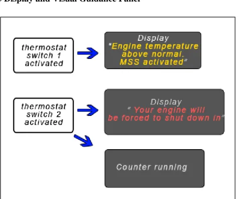
Figure 3.3: Display panel information.
The display panel will be design in small and neat to be easily placed on the dashboard or the visible place for the driver. The main function of the panel is to display
21
the warning to the driver about the engine’s heat condition and the current preventive action taken by smart heat management system (SHMS).
When thermostat switch 1 activated, the controller circuit board will sending the signal to the display panel for informing the driver about the engine temperature is above normal and the Mist Spray System (MSS) was activated. The driver should understand this signal and begin to take action by pull over the car in safe place or nearby workshop to check on their vehicle cooling system condition. The MSS will cool down the engine temperature and giving the user several kilometers more to drive to the target location.
If the temperature still rising and the thermostat switch 2 will be activated, the controller circuit board will sending the signal to the display panel informing the driver that the vehicle’s engine must be turn off to avoid from overheat. The timer will also be activated to provide an emergency time for the user to determining the safe zone to make an emergency parking. When the counter reaches zero the engine will be forced to turn off
22
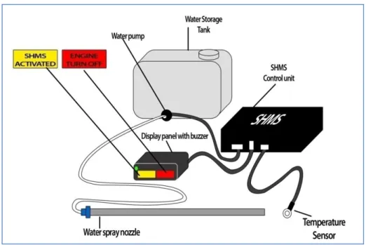
3.3.4 Complete Unit Of SHMS Unit Drawing
Figure 3.4: Drawing of Planned SHMS TABLE 3.1 : Bill Of Material For planned SHMS
Bil Of Material For Planned SHMS Unit
Bil Item
1 SHMS control unit
1 Storage tank with water pump 1 Display panel
2 Connection cable
1 Temperature sensor with connection cable 1 Water Hose
1 Water Spray Nozzle
A drawing for the complete unit will act as a guide for each component completion. The system has been checked to satisfy the entire objective. The next stage work is to identify the exact component to be used for the housing and the internal component including the connection of all the parts.
23 3.4 Drafting And Fabrication Process Flow
Listing the component of the
design and cost involved.
Preparation of the component and
fabrication equipment
Fabrication of conceptual design.
Assembly of the component Experiment of the
system and data collection Comparison with
mathematical model.
Check system abillty to complete
all the objective
Optimization of the system
SHMS ready to be use.
24 3.5 Fabrication Process
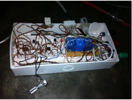
3.5.1 SHMS Control Unit Fabrication
Figure 3.5 : The Control Unit
Before the fabrication process begins, some additional research has been done to act as guidance for similar circuit diagram. The similar circuit diagram then studied for each component responsibilities and working principal. The analysis and experimentation for each component have been done as well to reconfirm the function of each equipment. The main objective of the control unit then has been draft to identify the objective of the control unit and to specify the each work that will be control by the control unit. After all the responsibilities of the control unit have been listed out, then the circuit diagram now goes to sketching stage. The sketched circuit diagram then again compared to the all control unit responsibilities to match all the desired function. After final confirmation of the diagram and job function of the circuit board, then the electronic component will be assemble into one complete circuit board. The circuit board then powered to be tested all the function. The error and not functioning segment will be revised for the alternative circuit diagram. After the circuit board satisfied and capable of doing all the job, the circuit board again will be checked to minimize the space of the main board used.
25 3.5.2 Water Spray Fabrication
Figure 3.6 : The water Sprinkler
The water spray tubing firstly fabricated as tubing with a row of small holes and tested for the pressure and the coverage area on the top of the radiator surface. The process of fabrication included the cutting and drilling of the tubing before assembled with the rubber hose as the connection for the tubing from the water pump. The next fabrication involved the usage of an adjustable water spray, the fabrication moved into next stage difficulties of fabrication. The objective is to connect the three water spray with aluminum tubing without any leakage with capabilities to handle high pressure water. The decision made to connect the entire three spray nozzle with rubber hose that is hiding inside the aluminum tubing. This method used to satisfy the objective to avoid leakage of the connection. The tubing will give the support to the rubber hose to give a rigid structure for easiness in installation process.
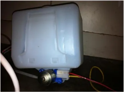
26 3.5.3 Water Storage and Pump Assembly
Figure 3.7 : Water Storage Tank and Pump
The component for the water storage tank is available in the market and the process needed is to assembly the water storage tank with the pump and to connect the pump with wire for power supply. The connection for the wire used 2 pin female and male connections for both end. The clip is make sure to be in a tight connection to avoid the wire from accidentally disconnect that may cause a harm.
27
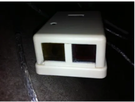
3.5.4 Display Panel Fabrication
Figure 3.8 : The Display Panel
The display panel was fabricated using the phone splitter as the base with internal modification to suit the purpose as the display panel. The smoked plastic then used to give distinguish the on and off of the display panel. A hole drilled to be installed with a green LED for power indicator. Then two of the connection socket in the splitter been modified for installation a LED inside the compartment and finally covered with smoked plastic cover. The buzzer that is initially require a big space to install, then trimmed to suit the spaced inside the splitter. The entire component installed inside the display panel are 3 LED with one buzzer. For the connection, the single core wire has been used and finally connected to the 8 pin small connector. The connection of the wire and the connector will require soldering job.
28
3.5.5 The Sensor Connection
Figure 3.9 : The NTC Temperature Sensor
The sensor function is to sense the temperature difference and the component used is the NTC (negative temperature coefficient) with the connection to an eyelet for easiness during installation process. Two NTC used to sense the temperature difference has been insert into the eyelet connection socket. For a better heat transfer the gap inside the connection socket has been filled with heat sink compound. Finally the connection has been wrapped with heat shrink for a clean finishing with tight connection. Another end of the sensor cable has been installed with 4 pin connector male and female socket.
This connection is to connect the cable with the control unit/
29 3.6 Model Development
3.6.1 Water Spray Unit Development
Figure 3.10 : Water Spray Trial 1 Trial 1
The water passage was previously tested for the optimum flow rate of water and optimum coverage over the radiator. The lesser holes over the tubing resulting higher flow rate due to higher pressure.
Figure 3.11 : Water Spray Trial 2
30 Trial 2
The water outlet have been tested using the nozzle and resulting a better coverage area and smaller water droplet size and simultaneously will elongate water discharge time.3 nozzle option have a better coverage area over the radiator surface.
3.6.2 The Control Unit Development
Figure 3.12 : Control Unit Trial 1 Trial 1
The initial power source of the circuit board is 9v DC that is more complicated to be installed on the car which is run on 12v DC.
Trial 2
The improvement have been made to have the control unit to handle a 12v supply by exchange the relay to avoid the relay from burned due to over voltage.
Trial 3
The final improvement made on the power supply to have it running on the vehicle power source which is 12v DC. The circuit been added few additional electronic component to avoid from damaging the circuit
31 3.6.3 The Display Panel Development
Figure 3.13 : Display Panel trial 1
Trial 1
The initial display panel was too simple and wasn’t delivering the message to the user. The display also missed a power signal to indicate the system is running.
Figure 3.14 : Display Panel trial 2 Trial 2
The display panel was improved by additional buzzer to alert the user and a proper panel with yellow and red backlight.
32
Figure 3.15 : Display Panel trial 3 Trial 3
The previous display font is unreadable due to small font and the significant symbol has been used instead. The symbol can be explained further in user guide book.
33 3.7 Experiment and Test Run
3.7.1 Introduction
This experiment is carried out to study the effect of evaporative cooling effect over the engine cooling system. The experiment was using a Mitsubishi MIVEC engine in block 15 as the subject. The first experiment was done by measuring the increment temperature during the engine warm up. The engine is located in a closed lab mounted at steel base support. The engine temperature is measured at the cylinder head of the engine using multi meter. The running temperature of the engine is around 71-75 °C.
3.7.2 Objective
The objectives of this experiment are
a) To investigate the effectiveness of evaporative cooling to cool down the engine b) To investigate the engine temperature curve when applied with SHMS mist spray
system at different stage of engine temperature.
3.7.3 Theory
The Principle Of Evaporative Cooling System
As water is evaporated, energy is lost from the air, reducing the temperature.
Two temperatures are important in the scope of evaporative cooling systems.
Dry Bulb Temperature
The dry-bulb temperature is the temperature of air measured by a thermometer freely exposed to the air but shielded from radiation and moisture. Dry bulb temperature is the temperature that is usually thought of as air temperature, and it is the true thermodynamic temperature. It is the temperature measured by a regular thermometer exposed to the airstream. Unlike wet bulb temperature, dry bulb temperature does not indicate the amount of moisture in the air.
34 Wet Bulb Temperature
The wet-bulb temperature is a type of temperature measurement that reflects the physical properties of a system with a mixture of a gas and a vapor, usually air and water vapor. Wet bulb temperature is the lowest temperature that can be reached by the evaporation of water only. It is the temperature one feels when one's skin is wet and is exposed to moving air. Unlike dry bulb temperature, wet bulb temperature is an indication of the amount of moisture in the air..
When considering water evaporating into air, the wet-bulb temperature, as compared to the air's dry-bulb temperature is a measure of the potential for evaporative cooling.
The dry and wet bulb temperature can be used to calculate the relative humidity.
Evaporation will take place when the humidity is below 100% and the air begins to absorb water. Any given volume of air can hold a certain amount of water vapor and the degree of absorption will depend on the amount it is already holding.
The term humidity describes how much water is already in the air; relative to the amount it is capable of holding. Air is saturated when it cannot hold any more water.
Imagine it as a sponge, if the sponge held half as much water as it was capable of holding, it would be 50% saturated. In the case of air, we would describe the Relative Humidity as being 50%.
Energy is required to change water from liquid to vapor. This energy is obtained in an adiabatic process from the air itself. Air entering an evaporative air cooler gives up heat energy to evaporate water. During this process, the dry bulb temperature of the air passing through the cooler is lowered.
35 3.7.4 Equipment preparation
Apparatus
The engine now equipped with SHMS to preset the effective temperature to deploy water spray onto the radiator frontal area.
SHMS unit consists of
1 SHMS control unit
This control unit will be used to preset the temperature for sensor 1 and 2. The sensor 1 will activate the pump to spray the water onto radiator frontal area and sensor 2 will turn off the engine.
1 Storage water tank with water pump
Storage water tank will be used to store the water and the water will be pump into water spray nozzle when activated by control unit.
1 Display panel and alert
The display panel used to give a visual and audio alert to the user by using a backlight panel assisted with buzzer.
2 Connection cable
The connection cable used to connect the SHMS to the engine power supply and to connect the SHMS to engine power wire for safety turn off purpose.
1 Temperature sensor with connection cable
The temperature sensor will measure the engine cylinder head temperature and send the signal to the SHMS control unit to be analyze for further action.
1 Water Hose
Water hose used to connect the water storage tank and pump to the water spray nozzle.
36
1 Water Spray Nozzle
Water spray nozzle used to spray the thin layer of water onto the radiator frontal area.
The engine is now equipped with SHMS and multi meter to measure the engine temperature
Figure 3.16 : SHMS setup
37
The NTC (negative temperature coefficient) and multi meter sensor probe attach to the engine cylinder head using eyelets to measure the temperature.
The connection cable connected to the engine switch for safety engine turns off purposed.
Figure 3.17 : Sensor location
Figure 3.18: SHMS connection to the switch
38
Two fans to simulate the air flow through the radiator when vehicle moving.
Three water spray nozzle arranged in row to spray onto radiator frontal area.
Figure 3.19: Fan configuration
Figure 3.20: Nozzle configuration
39 3.7.5 Procedure
1. The engine will be warm up and the temperature increment over time recorded.
2. The SHMS will be pre set at the desired temperature for water spray deployment.
3. The cooling fan will be turn off to raise the temperature of the engine at desired level.
4. The two fans will be turn on to simulate the vehicle on moving estimated at 30km/h
5. When SHMS activated, the time taken for water discharge and the temperature curve recorded.
6. The experiment will be repeated at different level of temperature that is 60°C, 80° and 90°C.
40 SHMS Start Temperature
Increased
Sensor 1 activated Display panel giving an alarm to the user while the
MSS spray water onto radiator
Temperature Reduced
Sensor 1 deactivate and
the MSS will stop runningSensor Sensor 2
activated
Display panel giving a danger
alarm to the user and prepare to shutdown the
engine.
Engine forced to shutdown
3.8 SHMS Process Flow Diagram
41 3.9 Tools And Equipment
3.9.1 Flow meter
Instrument to monitor, measure, or record the flow rate. This device will be used to gather the data of actual cooling system flow rate to be used in the simulation and system drafting as reference data.
3.9.2 Temperature Gun / Thermometer
To determine temperature of device, fluid, ambient, environment when perform the experiment.
3.9.3 Milling machine
The fabrication machine to be used in the fabrication stage where some part will needed a custom fabrication.
3.9.4 Drilling
An equipment to drill a hole 3.9.5 Soldering kit
An equipment to solder electronic chip and devices over the circuit board 3.9.6 Multi meter
Equipment used to measure voltage, temperature, current, resistance and connectivity for electrical devices and circuit board.
42
CHAPTER 4
RESULT AND DISCUSSION
4.1 Summary of the operation
The fabrication of the prototype is finally complete and tested for the operation and meets all the desired objective of the project. The SHMS should be able to avoid the engine from overheat that was caused by any reasons. The SHMS will also have the ability to cool down the engine temperature by cooling down the radiator by using the evaporative cooling principle. This capability will only effective with the presence of the cooling fluid that circulates inside the radiator and engine’s water passage. By having this capability, the user will have extra traveling distance to seek for help. On top of the protection, the SHMS will stop the engine before the engine’s temperature reach at the dangerous level of temperature that cause the engine overheat.
Below are several common causes of overheat that is successfully handled by SHMS
Thermostat Failure
Cooling system leaks
Leaky Head Gasket
Fan Failure
Leaky Water pump
Slipping Belt
Lower And Upper Radiator Hose Collapsing
Plugged or Dirty Radiator
Overworking the engine
The completion of the fabrication and experiment of prototype has taken four month that includes research on mechanical and electrical field. The prototype also had been through several stages of development for improvement to meet the objective.
43 4.2 The Complete SHMS Unit
Figure 4.1 : The Complete SHMS Unit
Table 4.1 : Bil of Material for SHMS Bil Of Material for SHMS Unit
Bil Item Cost
1 SHMS control unit RM 150
1 Storage tank with water pump RM 70
1 Display panel RM 15
2 Connection cable RM 10
1 Temperature sensor with connection cable RM 7
1 Water Hose RM 3
1 Water Spray Nozzle RM 9
Total RM 264 Water storage
tank & Pump
SHMS Control Unit
Water Spray Nozzle Display Panel
Temperature Sensor
44 4.3 Potentiometer Temperature Correlations
The SHMS prototype was build with the potentiometer to vary the preset temperature to be handled by the control unit. Below are the relations of the potentiometer value against the temperature sensor.
Table 4.2 Potentiometer and Temperature Correlations Temperature (celcius) Potentiometer Value (ohm)
93 277
91 301
89 331
87 362
85 387
83 459
81 472
79 517
77 540
75 570
73 609
71 669
69 725
67 772
65 854
63 939
61 980
59 1017
57 1089
55 1187
53 1228
51 1323
45
The preset potentiometer is the variable resistor that will restrict the discharge of current flow from NTC (negative temperature coefficient) to the ground. The current value will be measure by the IC (integrated circuit) to turn on the transistor and the current will power up the relay coil. These differences in resistances preset potentiometer will reflect the temperature value.
Figure 4.2 : Potentiometer vs Temperature
Based on the graph above, the potentiometer value is linear toward the temperature decrement. The lower preset temperature will have a higher potentiometer value. This trend will give estimation for the potentiometer value to preset the temperature.
0 200 400 600 800 1000 1200 1400
93 89 85 81 77 73 69 65 61 57 53 Potentiometer
value (ohm)
Temperature (celcius)
Temperature vs Potentiometer Resistance
potentiometer
46 4.4 Experiment Results
4.4.1 Experiment 1
The experiment 1 is measuring the engine temperature curve from the beginning of the engine start and operates the SHMS (Smart Heat Management System) water spray at 60°C.
Discussion
The engine temperature will keep increase to warm up the engine until it reaches the running temperature. When the SHMS applied on 60°C temperature, the engine temperature is still increasing since the engine is still not reaching its running temperature but the time to increase for each degree will take longer time. The SHMS runs after 6 minutes engine warm up until the water in the storage tank is finish 6 minutes later. The engine temperature increase around 60°C for the first 6 minutes before the SHMS runs and only rise around 12°C after the SHMS runs for the last 6
0 10 20 30 40 50 60 70 80
0 5 10 15
Temperature (Celcius)
Time (minutes)
Temperature Vs Time
SHMS applied at 60°C
Time (minutes)
Temperature (°C)
0 0
1 9
2 21
3 33
4 43
5 52
6 60
7 62
8 65
9 67
10 69
11 70
12 72
Figure 4.3 : Engine temperature during warmup
47
minutes. The temperature is still increase because the energy supplied to water molecules is not enough to evaporate the water and simultaneously carry the heat away but the SHMS is successfully slowing down the temperature increment.
4.4.2 Experiment 2
The experiment 2 is measuring the engine temperature curve when SHMS activated the water spray unit after the engine reach 81°C. Based on current water spray nozzle, water storage tank and water pump configuration, the water will be discharge in 6 minutes.
Discussion
After the engine is reaching its running temperature around 75 °C the engine fan was cut off to simulate the situation of the cooling fan failure. The temperature of the engine is increasing up to 81°C and then the SHMS activated the water spray onto the frontal area of the radiator surface. The engine is then blown by two fans to simulate the air stream pass through the radiator when the car is moving. The air stream is estimated as the car is moving around 30km/h. Based on the statistical data collected, the temperature
77.5 78 78.5 79 79.5 80 80.5 81 81.5
0 2 4 6 8
Temperature (Celcius)
Time (minutes)
Temperature Vs Time
SHMS applied at 81°C
Time (minutes)
Temperature (°C)
0 81
1 80
2 79
3 78
4 78
5 78
6 78
Figure 4.4 : Engine temperature when SHMS applie at 81°C
48
decrease about 3 degree in 6 minutes that is until the water in storage tank is running out. The temperature decrement is small due to small amount of the water evaporates because of insufficient heat energy transferred to the water. The lower boiling point medium or fluid can be used to increase the heat absorption into the medium and evaporate to carry the heat away.
4.4.3 Experiment 3
The experiment 3 is measuring the engine temperature curve when SHMS activated the water spray unit after the engine reach 91°C.
70 75 80 85 90 95
0 2 4 6 8
Temperature (Celcius)
Time (minutes)
Temperature Vs Time
SHMS applied at 91°C
Time (minutes)
Temperature (°C)
0 91
1 90
2 83
3 76
4 75
6 74
Figure 4.5 : Engine temperature when SHMS applie at 91°C
49 Discussion
The next temperature level is 90°C and the engine cooling fan is turn off until it reach the desired temperature before the SHMS activated the water spray system. The engine is then blown by two fans to simulate the air stream pass through the radiator when the car is moving. The air stream is estimated as the car is moving around 30km/h. The boiling temperature of the water is 100°C (212°F). When the water sprayed onto the frontal area of the radiator that is around 91°C, the water quickly absorb the heat and evaporates, This circulation carry the heat away and cooling down the radiator, cooling fluid and finally cooling the engine. Based on the data obtained, after 6 minutes SHMS runs, the temperature drop is about 17 °C. The higher engine temperature near the water boiling temperature, the higher amount of heat energy absorbed and more water evaporates. This will carry more heat away from the engine and cooling down the engine.
50
Below are the tables of the engine temperature increment. For the experiment 1 table, the temperature recorded for each minutes until the engine is reaching the running temperature. For the experiment 2 table, the engine was pre set at 80°C before the SHMS activated the water spray system. The time consumed for each degree Celsius decrement recorded. Finally the table for experiment 3, the engine was pre set at 90°C before the SHMS activated the water spray system and then the time consumed for each degree Celsius decrement recorded
Experiment 1 Time
(minutes)
Temperature (°C)
0 0
1 9
2 21
3 33
4 43
5 52
6 60
7 62
8 65
9 67
10 69
11 70
12 72
13 74
Experiment 2 Temperature
(°C)
Time
(minutes, seconds)
81 0m00s
80 0m27s
79 1m30s
78 3m06s
78 4m00s
78 5m00s
78 6m00s
Table 4.3 Engine Warm-up vs.
Time
Table 4.4 Time and Temperature Correlations
51 Experiment 3
Temperature (°C)
Time (minutes, seconds)
91 0m0s
90 0m57s
89 1m13s
88 1m19s
87 1m22s
86 1m24s
85 1m26s
84 1m31s
83 2m03s
82 2m07s
81 2m11s
80 2m20s
79 2m23s
78 2m28s
77 2m33s
76 2m58s
75 3m12s
75 3m36s
74 3m48s
75 4m00s
75 4m42s
74 4m54s
75 5m12s
74 5m54s
Table 4.5 Time and Temperature Correlations
52
4.4.4 Estimation Of Travelling Distance Gained.
The SHMS system will be pre set at 90°C for the first sensor and 100°C for the second sensor. The first sensor will give the signal to the control unit to activate the pump and spray onto the radiator to cool down the engine and the second sensor will give the signal to the control unit to turn off the engine. The sensor from the signal will have the range around 3°C from the preset temperature to give the signal to the control unit. Below is the estimation of the traveling distance gained by using SHMS based on the current configuration.
From the table for experiment 3 the time taken to drop the temperature 3°C from 90°C to 87°C is about 25 seconds. The total discharge time for 1 liter water based on current pressure and configuration is 6 minutes. The SHMS will run again the pump when the temperatures reach at 90°C. The experiment is the simulation of vehicle with cooling fan failure running at 30km/h.
The Assumption made
Vehicle move at constant speed 30km/h
The time cycle of temperature decrease and increase is constant
The air stream flow is constant
53
Based on this ON-OFF configuration, the pump will run when the temperature reach at 90°C and will turn off when temperature reach 87°C. The time taken is about 25 seconds to drop 3°C temperature. Since the pump with limitation of 1 liter storage water can run only in 6 minutes, so the number of times pump run will be
85 87 89 91 93 95 97 99 101
0 1 2 3 4 5 6 7 8 9 10 11 12 13 14 15 16 17
Temperature (Celcius)
Time (minutes)
Temperature Vs Time SHMS applied at 90°C
Temperature Drop Temperature increase
SHMS activated at 90°C
Figure 4.6 : Engine temperature when SHMS applie at 90°C
54
The estimation made, the engine will take around 35 seconds to increase 3°C back to 90°C before the SHMS reactivated that is 10 seconds longer due to existence of air stream when vehicle is moving. The total time for cooling down and increment (Tc) is 1 minutes. Total time gained before the water in storage running out
14.4 minutes is equal to 14 minutes 24 seconds. Finally for the temperature to reach the 100°C is about additional 1 minute 36 seconds. So the total time before the engine turn off is around 16 minutes. If the vehicle is moving about 30km/h, the total travelling distance gained is
(
)
55 4.4.5 Experiment Conclusion
Based on the experimented data collected, the objective of the experiment is now clear that the evaporative cooling is effective to cool down the engine temperature. There are several factor that influence the effectiveness of the evaporative cooling that are humidity, air stream flow rate, and temperature difference. The engine temperature curve obtained can be used as a reference to improve this project into another level of improvement. As a conclusion this experiment is meet the expectation and the project objective is success.
4.5 Demand Study
This project operation is basically based on monitoring the temperature of a subject and try to cool down the subject if the temperature is over the pre set temperature and finally shut down the subject when the temperature reach dangerous level as a safety measure to avoid the subject from damage due to overheat and cause damage.
The demand of this potential system is basically for everything that involves cooling system. Below are the few potential users that may need a system to monitor the temperature for their system.
Vehicle
Each vehicle has the cooling system and some of motorcycles also have fluid cooling system instead of air cooling system. The vehicle cooling system will be required to suit the operating range of the engine. The overheat issue will damage the engine, engine component and change the properties of the material.
That is where the SHMS can be used to avoid lots of money and time wasted on repairing the vehicle. A 30 Ringgit Malaysia upper water hose rupture can cause the engine overheat quickly and finally cost for around a thousand ringgit for repairing that might take around 2 or 3 weeks of time. The SHMS can save the