A smart in-situ gas lift is the latest emerging technology in oil and gas production. The purpose of this study is to select the design consideration for smart in-situ gas lift.
INTRODUCTION
Background
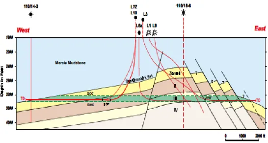
- Field Description
In this paper, the rare case of gas lift design is briefly discussed, which is in-situ gas lift design. This in situ gas lift system can be a great achievement to replace the conventional gas lift system.
Problem Statement
- Problem Identification
The main concern is to increase the production of the well by using the gas cap. This well has a large gas cap above the oil producing zone. The abundant amount of gas from the gas cap zone can be used as a lift medium to increase oil production in that well.
Objective and Scope of Study
Large sums must be invested if the artificial lift facilities are to be installed at the well platform. Plus, the space limitation on the platform makes the installation of other surface facilities for artificial lifting purposes quite difficult for the operators.
LITERATURE REVIEW
Artificial Lift
The artificial lift methods help start the dead wells so that they can reproduce again and increase the fluid flow rate from the bottom of the well to the surface (Tutschulte, 1945). Improper selection of artificial lift methods can lead to a reduction in production and high operating costs.
Conventional Gas Lift
The only requirement for the gas lift to be applied to a well is the availability source of injection gas (Blann & Williams, 1984; Kirkpatrick, 1959). The gas lift method can be used in two ways, namely continuous flow and intermittent gas lift.
Conventional Gas Lift Design Consideration
- Gas Injection Pressure
- Valve Spacing
- Tubing and Flowline Size
- Differential Pressure at the Point of Gas Injection
- Well Performance
- Water Cut
Beggs (2003) explained that the gas lift valve can be set at any depth and depends on the availability of injection pressure. Intermittent gas lift is applied by periodically injecting large volumes of gas under the formation of a column or liquid snap at the bottom of the well. The injection of gas into the intermittent gas lift is done by cycle process in which a new column of liquid must build up again at the bottom of well before the gas injection can be done (Takacs, 2005).
In addition, one of the design considerations that must be addressed in the design of gas lift system is the wellbore performance (Beggs, 2003; Hepguler, Schmidt, Blais, & Doty Mukherjee and Brown (1986)) stated that the differential pressure at the gas injection point is also an important design criteria for gas lift system. Furthermore, the effect of water cut should also be considered when gas lift system is designed (Blann & Williams, 1984; Mukherjee & Brown, 1986). According to Mach et al. 1983), one of the important considerations in completing the continuous flow gas lift design is the differential pressure at the point of gas injection and since production and valve spacing are based on differential pressure.
Well efficiency is one of the design factors to consider when designing a gas lift well (Beggs, 2003).
Smart In-Situ Gas Lift
1981)) emphasized the importance of considering water cutoff when performing gas lift, as water cutoff can affect the gas distribution and overall gas liquid ratio. Blann and Williams (1984) mentioned that the larger amount of gas had to be injected to create higher pressure extraction. The higher pressure reduction needed to overcome the wells that have high water cut, as the wells will have a small amount of gas to lift the formation oil to the surface.
Reservoir discharge due to flow in the water movement tank increases water cut leading to problems such as increased density of the produced fluid and formation of oil-water emulsion due to increased viscosity of the produced fluid and may reduce the production rate of the well. While Jin, Sommerauer, Rahman and Yong (2005) explained the concept of smart in-situ gas lift that source for internal gas lift can be used from a reservoir that has sufficient amount of energy and reserve. Plus, the life of a well can be extended by eliminating the high water cut effect. 2002) explained that continuous gas flow in the well can eliminate the high water cut.
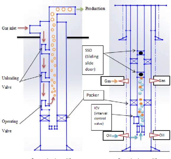
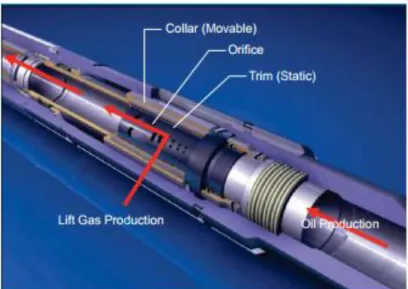
According to Vasper (2008), flowing gas is allowed to flow from gas formation through a flow control valve in the tube and the valve's opening can be controlled on the surface.
Smart In-Situ Gas Lift Design Consideration
- Interval Control Valve (ICV)
- Well Selection
- Setting Depth for Smart In-Situ Gas Lift Valve
- Valve Opening
In addition, the setup depth for a smart in-situ gas lift well plays an important role in making a good in-situ gas lift system (Al-Otaibi et al., 2006; Vasper, 2008). Meanwhile (Al-Kasim et al. 2002); Vasper (2008)) stated that valve opening can affect the performance and production rate of an in situ gas lift well. One of the main considerations when designing a smart in-situ gas lift system is the in-situ gas lift valve or specifically called interval control valve.
The design of the in-situ gas lift system must have a hydraulic control line connecting the control line on the surface and the operating valve in the well. In addition, a good selection of the well for the implementation of on-site gas lift can maintain a smart on-site gas lift. According to Peringod et al. 2011), the existence of continuous gas injection may be a good choice for an in-situ gas lift well.
In addition, the in-situ gas lift can also be applied to the depleted reservoirs that have some access for the source of gas from the nearest well within the reservoirs (A.K., 2010).
Application of Smart In-Situ Gas Lift
The application of in-situ gas lift offers several advantages for the oil and gas industry. According to Al-Kasim et al. 2002), the application of in-situ gas lift can save 3-4 days of drilling and increase fluid production. In addition, the in-situ gas lift design reduces the required platform load and replaces the conventional gas lift equipment with much simpler installation, reducing operating costs (Al-Otaibi et al., 2006; Vasper, 2008).
By using this method, capital expenditure (CAPEX) can be reduced and prove to be a cost-effective artificial (Konopczynski, 2007; Peringod et al., 2011). In an economic point of view, Jin et al. 2005) mentioned that by having a smart technology like in-situ gas lift, liquid recovery can be maximized by producing from small oil rims. In addition, in-situ gas lift has proven to be a smart system that can extend the life of a well by allowing continuous production from a high-water well (Warren et al also highlighted the benefits of using in-situ gas lift, which include stability of the production rate, less time it takes for a well to start up after plant shutdown, superior well integrity and footprint reduction.
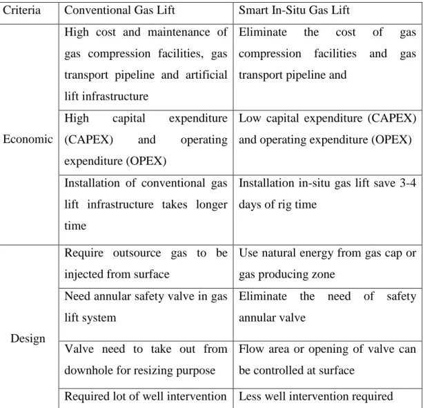
The comparison between the conventional gas lift and in-situ gas lift application can be summarized in Table 1.
METHODOLOGY
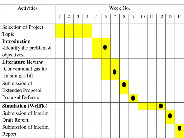
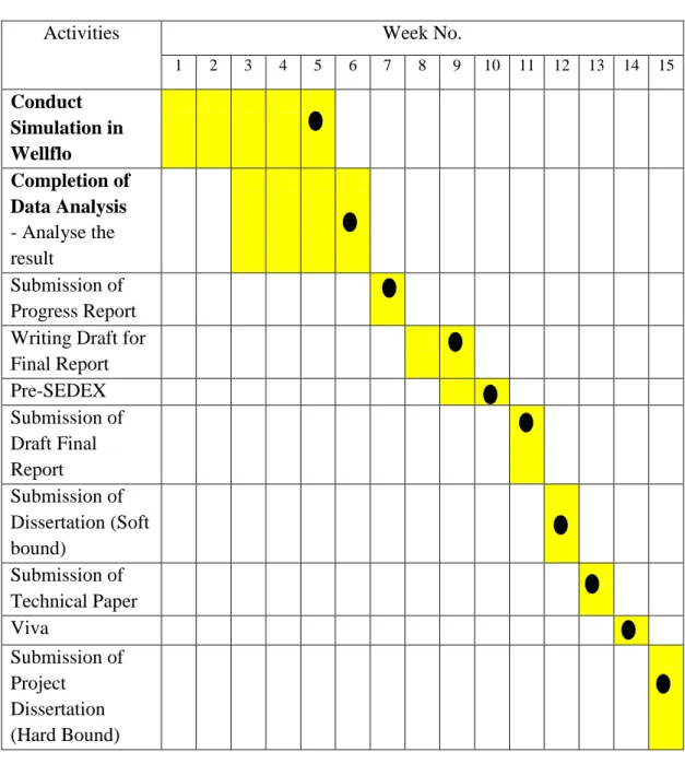
Gantt Chart
Week 5 Complete simulation work using Wellflo Week 6 Complete the data analysis obtained from simulation Week 7 Submission of progress report. Week 9 Completion of draft for final report Week 10 Preparation for Pre-SEDEX Week 11 Submission of draft final report. Submission of progress report Write draft for final report Pre-SEDEX Submission of draft final report.
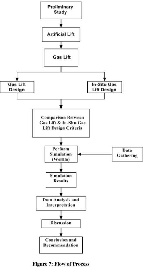
Flow of Process
- Preliminary Study
- Simulation Work
- Result and discussion
Plus, selection of design criteria for Gas Lifts and In-situ Gas Lifts are also examined and selected in the report. From this point, the comparison of the design for both gas lift and in-situ gas lift is drawn to gain more understanding of both design considerations. The main interest of this research will be the determination of design considerations for in-situ gas lift and prediction of well performance and production evaluation after performing in-situ gas lift system.
To perform the in-situ gas lift design in Wellflo, a model must be built and diagnostic analyzes performed. The in-situ gas lift well can be modeled in the software by specifying the components such as the gas lift valve, pipe size, etc. By performing simulation with Wellflo, the design consideration of a smart in-situ gas lift system can be applied in the software.
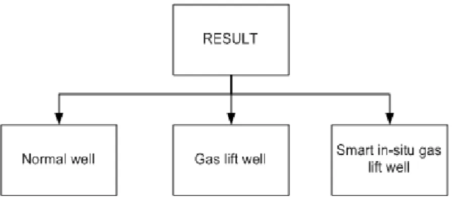
From this comparative study, the analysis of the smart in-situ gas lift well in the normal well and the conventional gas lift well can be clearly made.
RESULT AND DISCUSSION
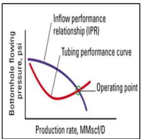
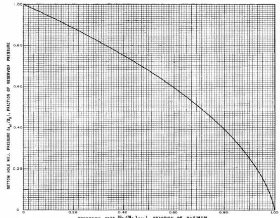
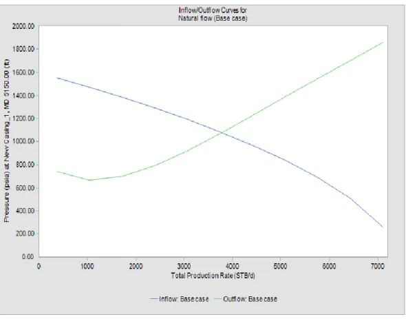
- Inflow/ Outflow Performance Relationship
- Gas Lift Design
- Conventional Gas Lift Valve Design
- Smart In-Situ Gas Lift Valve Design
- Advanced Smart In-Situ Gas Lift Valve Modeling
- Sensitivity Analysis
- Water cut analysis
- Valve differential pressure analysis
- Smart In-Situ Gas Lift Production Forecast
The implementation of a smart in-situ gas lift system in the well has increased total liquid production to 5031 STB/d compared to naturally flowing wells (3974 STB/d) and conventional gas lift wells (4350 STB/d). The oil production rate for smart in-situ gas lift wells has been improved by about 26% over the natural production well due to the help of the gas cap zone. In addition, the valve differential pressure is one of the factors to consider when designing a smart in-situ gas lift valve.
After finishing designing the smart in-situ gas lift system, the overall well performance needs to be analyzed based on several sensitivity parameters. From this observation, the smart in-situ gas lift well can still be produced at a higher rate, even with large amounts of water. Valve differential pressure is one of the most important design considerations for constructing a smart in-situ gas lift system.
Meanwhile, Figure 21 shows the valve differential pressure analysis for the intelligent in-situ gas lift well. At the estimated overall oil production rate, the well is expected to continue producing oil under the smart gas rise in place for more than 10 years. The summary of production forecast for the well after implementation of in-situ smart gas lift is presented in Table 10.
CONCLUSION AND RECOMMENDATION
Auto/Natural/In-situ Gas Lift- A new artificial lift approach for production of hydrocarbons from isolated pools by B&S Asset in Western offshore, Mumbai-A case study. Probe testing of gas lift valves for effective performance prediction and better gas lift design. Determining the most profitable gas injection pressure for a gas lift installation (includes associated papers 13539 and 13546.
SOLAG: An Intelligent Gas Lift Optimization System for Continuous and Intermittent Gas Lift Wells: Society of Petroleum Engineers. Using systems analysis can increase production by 200 percent in high volume gas lift wells. An Economic Approach to Oil Production and Gas Allocation in Continuous Gas Lift (Includes related documents 10858 and 10865.
Design of a gas lift system to increase oil production for high water offshore wells.