Blind Kcholocation
by
Sajee Mahamad
Dissertation submitted in partial fulfillment of The requirements for the
Bachelor of Technology (Hons) (Information & Communication Technology)
Universiti Teknologi PETRONAS
Bandar Seri Iskandar
JANUARY 2008
Approved by,
CERTIFICATION OF APPROVAL
Blind Echolocation
by
Sajee Mahamad
A project dissertation submitted to the Information Communication Technology Program
Universiti Teknologi PETRONAS in partial fulfillment of the requirement for the
BACHELOR OF TECHNOLOGY (Hons)
(INFORMATION COMMUNICATION TECHNOLOGY)
(Izzatdin Bin Abdul Aziz)
CERTIFICATION OF ORIGINALITY
This is to certify that I am responsible for the work submitted in this project, that the original work is my own except as specified in the references and acknowledgements, and that the original work contained herein have not been imdertaken or done by
unspecified sources or persons.
SAJEE MAHAMAD
ACKNOWLEDGEMENTS
First and foremost, I would like to thank my family and friends who have been supporting me and given me advice during the development of projects.
To my family, especially my parents, for giving me moral support as well as financial support to get materials for this project.
To my supervisor, Mr. Izzatdin Bin Abdul Aziz who has been giving me advice and ideas as well as feedbacks in order to get my project done and ensuring my project will fulfill the requirement. I really appreciate his guidance, advice and ideas which have broaden my scope of projects and ideas that I never thought of, before Blind Echolocation was being implemented based on his comments. Special thank to my supervisor for being able to tolerate and being so patient with me during our meetings although at times I was not
able to deliver what he wanted.
Thank you to everyone who has been involved in this project big thanks to you too.
Without everyone I mentioned above, I don not think I will be able to complete this project on time.
IV
ABSTRACT
A harsh fact that half million of children go blind each year shows that blindness is one of the significant problems that require a comprehensive care. Some people might consider blindness as a sickness which blind people should be pitied and disable to perform by themselves. In other way it might leads blind people to a "life of dependence"
which means that they can not do the activities as normal people can do without assist from others. This could be one of the factors that increase the unemployment rate among a blind community. Blind Echolocation is designed to meet the need of an effective way to assist the blind people to live independently with least help from other people.
Although a blind person has a visually impaired but he or she still can hear an echoic
sound to determine the direction and distance of the obstacles. Therefore the idea of this
project is to make use of Ultrasonic Sensor to produce a device which can be a useful navigation aid for the blinds. The goal of the device is to indicate the obstacles in an environment by triggering the alarm.
TABLE OF CONTENTS
CERTIFICATION OF APPROVAL
CERTIFICATION OF ORIGINALITY iii
ACKNOWLEDGEMENTS iv
ABSTRACT v
TABLE OF CONTENTS vi
LIST OF FIGURE ix
LIST OF TABLE ix
CHAPTER 1 INTRODUCTION 1
1.1 Background of Study 1
1.2 Problem Statement 2
1.2.1 Problem Identification 2
1.2.2 Significance of the Project 3
1.3 Objective and Scope of Study 3
1.3.1 Scope of Study 4
1.3.2 Deliverables 5
1.3.3 Project Planning and Management 5
v i
CHAPTER 2 LITERATURE REVIEW AND/OR THEORY
2.1 Background Knowledge 2.2 Echolocation component
2.2.1 Two-Dimensional Echolocation 2.3 Sensor
2.4 Sensor Controller Unit
2.5 The Design System
CHAPTER 3 METHODOLOGY AND PROJECT WORK
3.1 Methodology 3.2 Project Work
3.2.1 Planning 3.2.2 Analysis 3.2.3 Design
3.2.3 Implementation 3.3 Development Tools
CHAPTER 4 RESULTS AND DISCUSSION
4.1 Data & Gathering Analysis
4.1.1 The navigation aid system in supporting blindness
4.2 Discussion
4.2.1 Evaluation
CHAPTER 5 CONCLUSION
5.1 Conclusion
5.2 Recommendations
6 6 10 10 11 15 15
20 20 22 22 22 23 27 27
28 28 28
30 30
43 43 44
REFERENCES
APPENDIX
APPENDIX A APPENDIX B APPENDIX C APPENDIX D
APPENDIX E APPENDIX E
46
48 Work Breakdown Structure
Project Timeline
Use Case
Diagram Conceptual Flow Model of a blind navigation aid
Interview notes
The Figures of the developed product,
"Navigation Aid for Blind"
vin
LIST OF FIGURES
Figure 2.1 The principle of two-dimensional echolocation Figure 2.2 The ultrasonic sensor beam-spread specification
Figure 2.3 Illustration of the two interlacing sonic fields in the interlace mode Figure 2.4 Simplified block-diagram of the hardware
Figure 2.5 The Devantech SRF04 control protocol
Figure 2.6 Schematic diagram of the SRF04 interface to the OOPIC board
Figure 3.1 Incremental PrototypingFigure 3.2 The schematic diagram of Ultrasonic Sensor circuit Figure 4.1 Response blind about to implement a navigation aid Figure 4.2 User acceptances on using a navigation aid
Figure 4.3 User acceptances on using a navigation aid Figure 4.4 Usability test on moving objects
Figure 4.5 Usability test on still objects
Figure 4.6 Usability test for distance between 0.1-1 Meters Figure 4.7 Usability test on raining condition
Figure 4.8 Usability test on different level area Figure 5.1 A/D converters to DSP to D/A converter
LIST OF TABLES
Table 1 Detection quality under specific weather conditions
Table 2 Where it detects
Table 3 Ability to detect objects
Table 4 Tools and Utilities
Table 5 Usability test result Table 6 Result of reliability test
CHAPTER 1
INTRODUCTION
1.1 Background of study
In fact the blinds may utilize echolocation as a tool to localize the obstacles in an environment. Echolocations compose the blinds to decrease their dependence on the visual system which give them an advantage for navigation.
In past fifty year research has revealed that the auditory system is a major tool of perception employed by blind human [1]. Many researchers attempt to discover a solution to improve the blinds' mobility in terms of convenience and safety. Many of these devices apply ultrasound to detect objects and to inform the user through the auditory system [2] however these devices have not gain much acceptance from the users.
The reason might be that the device was not satisfactory in determining an accurate location of the obstacles. Clearly, it is difficult to evaluate a complex sound signal, and a considerable learning period is needed before actual use or, in other cases [2], the indication is too poor information. Therefore, we have decided to pay more attention to the sound indication and applied a digital signal processor in our device in order to provide a flexible and sophisticated stereo signaling sound feedback [2].
A navigation aid is considered as an effective tool which assists visually impaired people to perceive the environment. In this case we can say that bats are well-known example, which use ultrasonic echolocation for navigation and hunting under poor lighting condition without vision, and today this technique is widely use in mobile robots.
1.2 Problem Statement
1.2.1 Problem Identification
Blindness is a disease which creates a problem to the visual ability of the blind person but this fact does not show that this group of people is absolutely disabled. In other words, blind people are able to perform the activities which normal people can do, only
that they might face some difficulties in carry out those activities. The real problem of the
blind people is not the consequences of the disease but it is misinterpretation of the general public on this disease. As mention in the National Federation of the Blind, "The real problem of blindness is not the loss of eyesight. The real problem is the misunderstanding and lack of information which exist. If a blind person has proper training and opportunity, blindness is only a physical nuisance." [3].In fact, visual impairment covers a whole range from people who are only slightly affected to the very small proportion who are totally blind and cannot distinguish light from dark. Only a small minority of partially sighted people have no useful sight. All people experience deteriorating eyesight with advancing age. Blind and partially sighted people are more dependent on their hearing for information gathering [4].
People who have been blind since birth may have missed out on some opportunities for learning to read, for example through the experience of signs and labels in everyday life.
They will also have a conceptual structure for such concepts as distance, dimensions and scale that is not drawn from visual images. They may also have missed out on gathering everyday information about the world around them, which sighted people take for granted. They may therefore need to be introduced to new situations in a practical experiential manner.
1.2.2 Significance of the Project
Blind Echolocation is a project which applies the knowledge and the information gain thought out the research process. The rational for having a navigation aid system is that,
which allows them to detect the direction and distance of the obstacles then it will generate sound effect to identify the location of the objects.
Below are lists of reasons why blind people are encouraged in using a Blind Echolocation system:
• Assisting the blind to live independently by performing the daily activities with the least help from people surrounded.
• Improving opportunities for the blind to work together with other people.
• Integrating the blind into the public on a basis of equality especially in educational aspect.
• Decreasing the possibility to get an accidents and make life more secure Navigation aid requires investment of time and effort in developing new skills, new approach, and new resources: perhaps time and effort that would otherwise be spent on research. However, time and effort can be saved in the long term. The key to develop the blind echolocation is to improve the effectiveness and quality of blindness living life. The blind also expect to be able to work with the general community and lead to the independent life.
1.3 Objective and Scope of Study
• To study on the consequences of blindness problem
The blindness is an interesting topic as many researchers have granted their attention to discover the solutions which are able to solve the problem leads by this disease. We can see that currently the numbers of blind people are increasing day by day especially in a childhood so it has proven that the blindness problem is required an inclusive concern.
• To develop a system which assist the blind to indicate the environmental
obstacles.
According to the blindness problem mentioned before we might consider a navigation aid to be one of the solution to solve this problem. Since blind is able to hear sound from the
echolocation so to develop a system which enhance theircapability to navigate and detect
the direction and distance of the objects will lead them to a new environment which creates an independent life for them.1.3.1 Scope of Study
Blindness is more common in poor country then in rich country. Children in low-income countries are four times more likely to be blind than those born in high-income ones such as the UK. The main cause - corneal scarring - is rooted in poor diet (lack of Vitamin A) and inadequate sanitation [5].
Thailand is one of the countries which account the blindness problem. Thailand
Association of the Blind (TAB) is the largest self-help organization of the blind inKingdom of Thailand established in 1967 by a handful number of blind people, the TAB
has grown slowly but purposefully that it is now realized both with in Thailand and internationally as the national organization for self-expression and self-determination of blind people in Thailand. We now have over 2,300 members from all over Thiland.Currently, Mr.Prayad Poonongong is the elected president. Our national office is located in Bangkok with four other regional offices. Mr.Kitipong Sutthi, a college educated blind man, is the executive director. We currently have 16 paid staff members altogether. [6]
The Blind Echolocation is going to be developed to address the similar problem has happened in Thailand by focusing more on Songkhla Association of the Blind, one of the members of TAB established on September 5, 2004 and allocate at Southern part of Thailand. The minimum required age for the member is 15 years old and above. The main purpose of the association is to assist the blind to live with higher quality of life by
offering job opportunity to the member and also conduct several programs to enhance the
capability to live independently.The navigation aid System will be developed as the following scope:
• The area of performance work will relate only with blind at the age of 15 years
old and above.
• The main focus is to address the current problem by adopt a navigation aid
1.3.2 Deliverables
Some of the deliverables are listed below to meet the users' needs:
• To assist blind people to be able to executed the basic activities by themselves.
• To encourage blind people to work together with other people.
• To develop a device which is supported the navigation capability of blind people
by using sensor system.1.3.3 Project Planning and Management
Project planning and management is important to ensure that the project that will be developed runs well and could be delivered on time. It should be carefully planned and manage well, as well as organizing effort to accomplish goals or task; in this case, developing navigation aid for the blind. Managing a project includes developing a
project plan, which defines objectives and goals, specifying tasks and how to achieve
stated objective. Resources or research on materials needed also need to be done toensure the project runs smoothly. The author has come up with a projecttimeline to plan
the research for part I and II (appendix A).For the normal IT project, the project has been divided into 4 phases according to the SDLC (Software Development Life Cycle) that are planning, analyzing, designing and implementing. The Methodology or Project Work will be discussing details in Chapter 3.
CHAPTER 2
LITERATURE REVIEW
2.1 Background Knowledge
Human beings generally navigate visually, using vision to determine the location and distance of objects. Besides the standard tools of navigation the blind use, such as a cane or a seeing-eye dog, some blind people have been able to develop a technique called echolocation. The discussion of the ability of blind people to use human echolocation to navigate could be as below:
While the phenomenon known as human echolocation has been known since the 1950s, it was defined and developed by a man named Daniel Kish. Blind from birth himself, Kish is the Executive Director of the World Access for the Blind where he teaches human
echolocation techniques as well as other mobility techniques for the blind. Human echolocation, after much practice, can help a blind person determine the height, width, location, and even density of environmental features. The most famous practitioner of human echolocation, besides Kish, is a teenaged boy named Ben Underwood.
Underwood has been featured on CBS and ABC News, as well as the Ellen DeGeneres Show and People Magazine. Underwood has been blind since early childhood, having his eyes removed due to a cancer. Nevertheless, using human echolocation techniques, he can navigate and even play games such as foosball with the same confidence as a sighted person. The remarkable thing is that Underwood was not taught in the echolocation technique, but like Daniel Kish seems to have developed it on his own. [7]
Using human echolocation, the blinds can observe their surrounded environment through the auditory system. The blinds can enhance their capability of hearing by applying echolocation concepts which help them to determine the direction and distance of the object. The proper training makes it possible for the blinds to decrease their dependence on other people.
From 1944 to 1947 the Committee on Sensory Devices of the National Academy of Sciences developed eighteen different portable devices to aid the blind in avoiding obstacles. Only two performed sufficiently well, but these devices performed analysis on a point-by-point basis. This point-by-point analysis can be compared to a flashlight which
"reveals only the small portion of the environment that falls within its scope." Much remains to be learned about the physical properties and cues which affect object perception by the blind. [1]
The blindness has become an interesting issue as an associated instituted attempt to solve the consequences of this disease by putting an effort to develop a tool to assist the blinds and improve their quality of life. Although the work was not successfully developed but
it became an initial idea for the future research.
These issues were addressed by many scientists, including Diderot who, in 1749, recorded his observation that a blind person has the ability to perceive the presence and distance of objects. Since then different theories have been suggested to explain for this phenomenon. One theory described object detection through the use of skin sensitivity to temperature or pressure. Another theory offered pressure on the tympanic membrane (which vibrates with sound waves in the inner ear) as the mechanism of detection. Mystic theories assumed object detection through utilization of such phenomena as magnetism, electricity, or a sixth sense. The blind themselves had different interpretations of the mechanism of their perception. [1]
Many scientists aim to discover the theory to address blindness issues focused more on sensory system in human body as a mechanism of detection since Diderot presented that a blind is able to recognize the location and distance of the obstacles.
In 1944, Supa, Cotzin, and Dallenbach discovered that stimulation of the auditory system, rather than stimulation of the skin by air and sound waves, was necessary and sufficient for detecti ng obstacles. When air-waves were prevented from impinging on the exposed skin of blind and blindfolded sighted human subjects, the subjects, by listening to footsteps, could still detect obstacles through their uncovered ears. When audition was prevented and the skin left exposed, subjects could not detect the obstacles. [1]
The research has proven that the auditory system is a major mechanism deploy by the blind. Thus, in bats and humans, eliminating sound production or sound reception decreased or eliminated the ability to detect objects when sight was not available.
After determining the importance of hearing, researche rs focused on specific properties of sound were important. Cotzin and Dallenbach (2) found that in order for blind subjects to avoid colliding with a wall, they must hear changes in the pitch of a sound, with a frequency above 10 kilohertz. The nature o f sound is such that higher frequencies allow better resolution of echoes reflected from small targets. [1]
According to the properties of sound, the navigation aid should be able to generate a sound with a frequency above 10 kilohertz. By making use of the ultrasonic sensors with nominal frequency 40 kilohertz is achievable to determine the two-dimensional position
of the obstacles.
In 1962 Kellogg found that objects closer to the observer were observed to be larger in size than the standard of same diameter, whereas objects farther away were determined to be smaller. Kellogg also found that the blind had the ability to discriminate objects of different size. In 1965 Rice showed that percent correct detection of an object was a function of the size and distance of the object from the observer. [1]
The distance and size of the object can variant the localization capability of the blinds, at a greater distance, objects needed to be larger in diameter to be detected by the blind. The ability to detection object becomes more difficult as the sound intensity of the echo becomes lower when the object is placed farther from the blinds. As object size increased, the blinds' ability to detect the object improved.
During the past 30 years a number of electronic travel aids have been developed. Best known is the C5 Laser Cane, which is based on optical triangulation with three transmitters and three photodiodes as receivers. An UP channel detects obstacles at head- height, the FORWARD channel detects obstacles from the tip of the can forward, (in the range of 1.5-3.5m) and the DOWN channel detects drop-offs in front of the user. The
Mowat Sensor is another hand-held device that informs the user of the distance to
detected objects by means of tactile vibrations, where the frequency of the vibrations is inversely proportional to the distance between the sensor and the object. The Mowat sensor is a secondary aid for use in conjunction with a long cane or a guide dog. . The Mowat sensor has been found helpful, and users feel they benefit from it. The Russell
Pathsounder is one of the earliest ultrasonic travel aids. Two ultrasonic transducers are
mounted on a board that the user wears around the neck, at chest height. This unit provides only three discrete levels of feedback (series of clicks), roughly indicating distances to objects. The Pathsounder does not require active manual scanning of the environment by the user, but torso movement is the only search strategy potential. The Binaural Sonic Aid (Sonicguide) comes in the form of a pair of spectacle frames, with one ultrasonic wide-beam transmitter (55° cone) mounted between the spectacle lenses and one receiver on each side of the transmitter. Signals from the receivers are shifted and presented separately to the left and right ear. The resulting intramural amplitude
difference allows the user to determine the direction of a reflected echo and thus of an
obstacle. The distance to an object is encoded in the frequency of the demodulated low- frequency tone, which together with the wearer's head orientation provides clear information about the object's location. As the Sonicguide does not require active manual scanning, it can serve as a secondary device, in conjunction with an additional hand-held device or a guide dog. [8]
The motion of a blind person is required a detection system to detect obstacles along the path and avoid them. Using multiple ultrasonic sensors that face in different directions replaces the need of manual scanning the surrounding by the blind. Although the Russell Pathsounder and the Sonicguide do not require manual scanning, their effective exposure of the surroundings depends on the direction of the head or body. Multiple sensors, on the
other hand, can cover a large area, regardless of the user's orientation. Furthermore, no additional measurement is required when an obstacle is detected, since its relevant distance and direction are determined simultaneously by the multi-sensor system. In addition, the obstacle avoidance system can guide the blind traveler around obstacles.
2.2 Echolocation component
2.2.1 Two-Dimensional Echolocation
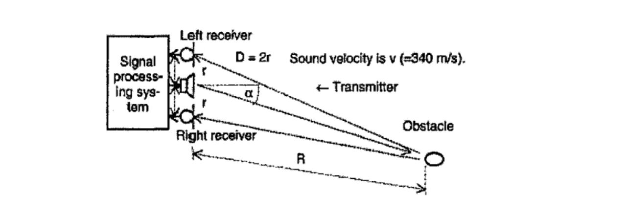
The following figure shows how to determine the distance and direction of an object by means of ultrasound reflections. [2]
ing sys
tem
Left recefver
J^Cp--^ D*2r Sound velodty is v(=340 m/s).
Jj^^z—-^ ^_Transmitter
[& ^"
nPL^^--- ^ O ^ Obstacle
Right recerver
f6— o
Figure 2.1: The principle of two-dimensional echolocation
The localization method is as follows: The transmitter emits an ultrasound impulse of given (Timp) length. First a direct wave arrives in the receivers, therefore the inputs should be inhibited for a period of (Ti, + r/v). Later, depending on the distance (R) and direction (a) of the obstacle, a reflected impulse arrives first in the nearer receiver and then in the farther one. At this point, the critical task is to determine - as, precisely as possible - the instant when the reflected impulse, arrives at the left and the right side, respectively. Let us consider now the simplest way of detection, the "threshold method"
illustrated in Fig.2.2.1 for the left one of the receivers. When the received signal first
exceeds the receiver's threshold, the echo is detected and the measured "to-and-fro"
propagation time (t L) is stored. Though this simple method is sensitive to noise, it should be mentioned that it could work without envelope-demodulation of the received signal; so it can provide the basis of more sophisticated methods like distance varying or adaptive threshold methods. Using the left and right time delay of the echoes (tL, tR), the coordinates of the detected object can be calculated. Assuming that R » r, the following approximations can be used: [2]
• The distance is:
2
• The direction is calculated from the difference of time delays:
a-arcsm——u— •
The Effects of More Realistic Conditions [2]
• If there is more than one obstacle, the nearest one will be detected. This is quite convenient for us, and does not pose any critical problem.
• If there is only one obstacle but its size is relatively large, then similarly to the previous case, clearly its nearest part will be detected. The extrapolation to more
than one or to concave obstacles is now obvious.
• If the surface of the object to be detected is poorly reflecting (because it is too small, or its material is too soft, or the angle of the surface to the receivers is too sharp) then, unfortunately, such an object cannot be detected or only from very short distances. Actually, that is the main limitation of ultrasonic echolocation.
2.3 Sensor
As there are many types of sensor are existed so that it is important to decide on the most suitable sensor for the developed system. The tables below illustrate a sensor type comparison chart. [12]
11
Detection quality under specific weather conditions
Weather
ypeof
iensor
Day Light Glaring sonlight
Darkness Dirt/Mud Rain Fog Snow Ice/Slee
t
trasonic Pulse
Very Good,
Very
accurate
Very Good,
Very
accurate
Very Good,
Very
accurate
Good, Very
accurate
Very Good,
Very
accurate
Very Good,
Very
accurate
Very Good,
Very
accurate
Very Good,
Very
accurate
Radar
Good, Accuracy
issues
Good,
Accurac
y issues
Good, Accuracy
issues
Good, Accuracy
issues
Good,
Accurac
y issues
Good,
Accurac
y issues
Good, Accuracy
issues
Good,
Accurac
y issues
Video Very
Good Poor
Good, sometimes
tricky
Very
Good Good
Poor,
Hard to read
Very
Good
Good, Can fog or ice up Table 1: Detection quality under specific weather conditions [12]
• Ultrasonic Pulse - not affected by most weather conditions and accurate down to
1/10 inch.
• Radar - Slower, less accurate, either vehicle or obstacle must be in motion.
• Video - Harder to read at night, does not give distance or warning.
Where it detects
Distance sof
o r
Object next to subject 5 feet behind
10 feet behind
15 feet behind Blind
spots between
sensors
isonic
3
Yes, Very accurate
Yes, Very
accurate
Yes, Very
accurate
Yes, Very accurate
No
i r Yes,
Accuracy issues
Yes, Accuracy
issues
No detection
No detection No
0 Some Times Yes Yes No No
Table 2: Where it detects [12]
Ability to detect objects
Type of Objects to Objects Moving Objects Still objects
Sensor the side of
the subject
Behind
subject
Ultrasonic Very Good. Extremely Extremely Good. Extremely Good.
Pulse No motion Good. No No motion No motion
required. motion required.
required. required.
Radar Varies & Very Good, Good. Accuracy Unreliable
subject but subject or issues.
must be in object must be
motion. Can in motion false.
Video Good Very Good Very Good Good
Table 3: Ability to detect objects [12]
According to sensor type comparison chart above, Ultrasonic sensor could be considered as the most effective sensor among other. Ultrasonic sensors work on a principle similar to radar or sonar which evaluates attributes of a target by interpreting the echoes from radio or sound waves respectively. Ultrasonic sensors generate high frequency sound waves and evaluate the echo which is received back by the sensor. Sensors calculate the time interval between sending the signal and receiving the echo to determine the distance to an object. [12]
Systems typically use a transducer which generates sound waves in the ultrasonic range, above 20,000 hertz, by turning electrical energy into sound, then upon receiving the echo turn the sound waves into electrical energy which can be measured and displayed. [12]
The technology is limited by the shapes of surfaces and the density or consistency of the material. For example foam on the surface of a fluid in atank could distort a reading. [12]
Selecting the sonar's detection range affects two major parameters: [8]
13
• Preview distance. An important parameter for blind travelers is the preview distance. An experiment conducted by Clark-Carter showed that the optimal range of an ultrasonic travel aid is 3.5 meters. This range is safe for the average walking speed of sighted people (1.3 m/sec) and is within the reach of conventional
ultrasonic sensors.
• Ultrasonic firing timing. The obstacle avoidance system includes an algorithm for detecting and rejecting ultrasonic noise and crosstalk, even when firing the sensors rapidly. However, the effectiveness of this algorithm is inversely proportional to the preview distance. Thus larger preview distances increase the probability for erroneous readings.
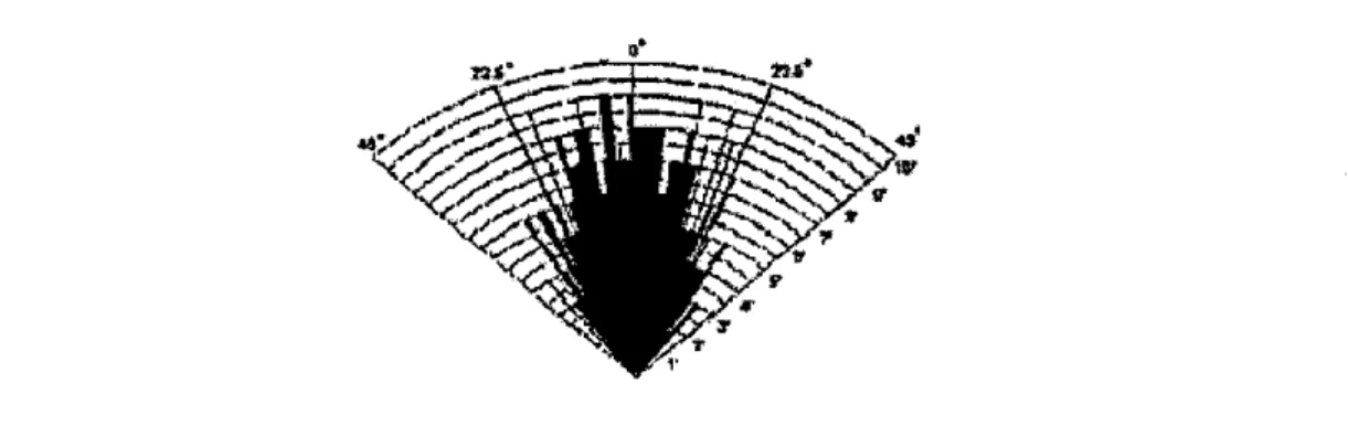
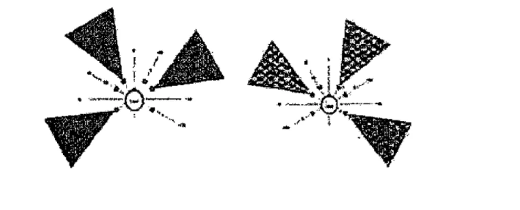
The ultrasonic sensor beam-spread specification (Figure 2.3) shows the possibility of a beam overlap between adjacent sensors in this particular geometry. To eliminate CO- channel interference, two types of triggering sequence modes were tested. The 'sweep mode' triggers and records distance one channel at a time, starting from -120" to
the+120" direction. This mode takes the maximum amount of time. In the 'interlaced
mode' illustrated in Figure 2.3.b, two groups of non-adjacent sensors are triggered in an alternating fashion. [11]
Figure 2.2: The ultrasonic sensor beam-spread specification
The interlaced mode was found to require 40% less time than the sweep mode to acquire
a complete panoramic range reading. [11]Figure 2.3: Illustration of the two interlacing sonic fields in the interlace mode
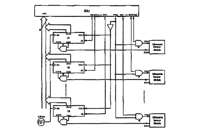
2.4 Sensor Controller Unit
The Sensor Control Unit (SCU) is designed around an OOPIC-1I [3], which is a single board microcomputer based on a Microchip PIC16F77 microcontroller, featuring 24 bit digital I/O, serial and I C interfaces. The functions of this unit include: sensor interface, data pre-processing, and communications with the host system, command interpretation and command execution. [11]
2.5 The Design System
Based on the research paper on DSP-based Ultrasonic Navigation Aid for the Blind was developed by TSP Lab, Department of Telecommunications and Telematics, Budapest University of Technology and Economics which introduced a novel navigation aid for the blind. The system detects obstacles in front of the user by the help of ultrasonic echolocation and indicates the distance and horizontal position of the nearest detected object by spatial stereo sound effects. The instrument is based on a fixed-point digital signal processor. [2]
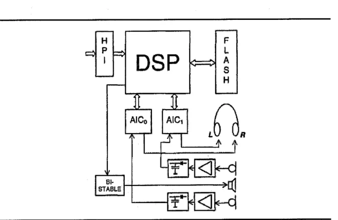
The simplified block diagram of the hardware can be seen in Figure 2.5.a: The main
characteristics of the applied TMS 320VC5402 type DSP are: 16-bit fixed point, low
voltage (VCore =1.8 V, VIFO =3.3 V), 100 MIPS max., 16 k word on-chip RAM. [2]15
<=3 K =&
Figure 2.4: Simplified block-diagram of the hardware
The Host Port Interface (HPI) of the DSP is used 'to download the program from a host PC to the DSP, but the processor can boot from the flash RAM too, once the program is stored. This is a very flexible configuration, since the modification of the software through the HPI is quick and simple while the flash RAM provides portable operation.
[2]
Two parallel Analog Interface Circuits (AICs) type TLV320AIC10 are used with dual purposes. They digitize the envelope-demodulated echo signal of the left and right receiver and provide the digital-to-analog conversion of the binaural sound for the earphones. The parameters of the codecs (22 kHz sampling rate and 16 bit resolution) are suitable for both tasks. [2]
As Figure 2.5.b illustrates, the signals of the receivers are amplified and then envelope- demodulated. Since the signal envelope contains all available information from the
environment (except the Doppler-shift, which is neither significant nor useful for us), the digitization of the original modulated carrier is not necessary. The ultrasound transmitter
is driven by the DSP's timer out- put through a flip-flop producing a frequency of 40 kHz.
Lower frequencies would be better considering attenuation, but it would also disturb sensitive animals (like guide-dogs), which is not allowable in our case. [2]
Another research paper on A Pocket-PC Based Navigational Aid (SRF04) for Blind Individuals was developed by Digital Signal Processing Laboratory, Biomedical Engineering, and Electrical & Computer Engineering Departments, Florida International University which describes a Pocket-PC based Electronic Travel Aid (ETA) that helps a blind individual navigate through indoor environments. The system detects 3 surrounding obstacles using ultrasonic range sensors and the travel direction using an electronic compass. The acquired information is processed by a Pocket-PC to generate a virtual acoustic environment where nearby obstacles are recognizable to the user. This virtual environment is played buck through stereo headphones, so that the user can perceive surrounding obstacles and the direction of the Earth's magnetic North using spatialized 3D sounds. [11]
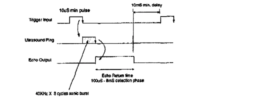
The SRF04 module contains a Trigger input and an Echo output. The protocol shown in Figure requires the Trigger input of the sensor module to be pulsed high for a minimum duration of lOpS. At the falling edge of the Trigger pulse, the module emits a burst of ultrasonic energy - known as the 'ping'. Immediately after the ping emission, the Echo output of the sensor goes into a high state and remains high until the receiving circuit detects the echo. The instrumental challenge is essentially to measure the duration of the Echo pulse, since the detected range is proportional to the Echo detection time.
17
lOuSmin puis*
Trtggermpui I 7^
uurasounaPtng
Eew output
iOmSmin.dany
Ectw fatum Sme ioouS • SmS dBrteson ptase
«KMzX acydnuniebuM
Figure 2.5: The Devantech SRF04 control protocol
The range sensor interface circuitry (Figure 2.5.c) features highly flexible configurability, this allows triggering and range recording of any desired combination of the six ultrasonic range sensors. Six independent %bit up-counters have been assigned so that each ultrasonic range sensor records the echo detection time with reference to a time-base.
All counters are reset when the master ping (PING) signal is activated. The master ping signal is gated through a set of AND gates which are controlled by the six ping mask signals M(n) for each channel. The bit pattern on these signals determines which sensors are activated when the PING signal is triggered. Upon receiving a trigger, the 'Echo' output of each sensor enables the count operation on its associated counter. Count operation is suspended immediately after the ultrasonic echo is detected by the related sensor and the Echo output is deactivated. The S(n) selection lines are used to sequentially transfer the counter values into the microcontroller through an 8-bit data bus.
The count values are held in each counter until reset during the next ping cycle. Counter roll-over prevention has been implemented by a set of NAND gates that disable the count-enable signal of each counter when the count value reaches 255.
axi
77 4*
M I W I W - *hi i»waw-p-ijWijuwi
a *•
V
>a*
t w i
•*
- >W V"*J* JEflLJ It LBVtt
tf
P I
UtttiufeUmIa
«H_
QHumui'Il
k**l.
1 Qyrg
*«WWf UbdM
Figure 2.6: Schematic diagram of the SRF04 interface to the OOPIC board
19
CHAPTER 3
METHODOLOGY AND PROJECT WORK
3.1 Methodology
In software development, a prototype is a basic working model of a product which demonstrate the purposes or as part of the development process. In the systems development life cycle (SDLC) Prototyping Model, a basic version of the system is built,
tested, and then reworked as necessary until an acceptable prototype is finally achievedfrom which the complete system or product can now be developed. The benefits of using
prototyping are:• Enable the developer to improve system usability in which closer to the user
requirements• Enable the developer to quickly designthe structure of the device.
• Reduced the development cost since rework during development is avoided.
The system developed which achieves customer satisfaction is not done in a single step.
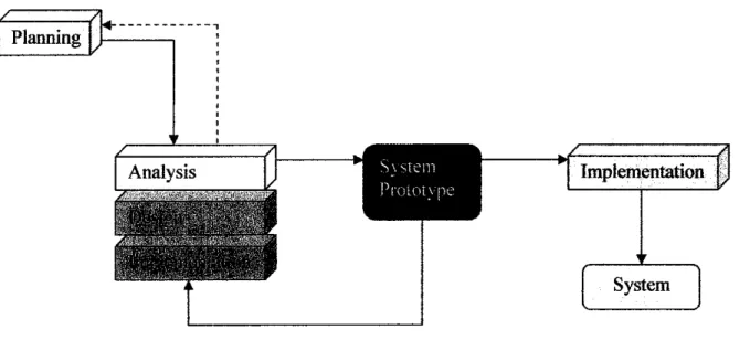
It involves series of steps in a software development process. To develop a navigation aid, it is best to apply the methodology named prototyping-based. Prototyping-based- based methodology (figure 3.1) performs the analysis, design, and implementation phases concurrently, and all three phases are performed repeatedly in a cycle until the systems is completed.
S\stem Pi'OLotvne
Implementation
System
Figure 3.1: Incremental Prototyping
In a prototyping model, the product features are added into each of several prototypes.
Typically, development starts with the external features and user interface and then, adds features as prototypes are developed. Requirements and architectural design can be done up front and then each prototype developed as the project progresses. [14]
The reasons of using this method are:
• Allows large systems to be installed in phases
• Helps to avoid the delays between specification and implementation
• Core system features are provided early
• Users are not overwhelmed with a complex level of functionality in one go
• Suitability and appropriateness of key requirements can be checked
• Less essential features can be added later
21
3.2 Project Work
3.2.1 Planning
In the planning phase, the project initiation is implemented where the student is requested to select the project topic and produce a project proposal. The project proposal was submitted to the Final Year Project (FYP) committee member to evaluate the topic proposed in order to make sure that it meets the FYP requirement. The next task will be the project management which involves analyzing the technical feasibility of the project as well as the organizational feasibility. The tasks that involved are:
• Create work breakdown structure (Appendix A)
• Create the project timeline (Appendix B)
• Identify the scope of the project which is blind in Thailand (15 years old and above)
• Estimate the project size and cost by conducting a survey about the price of the device such as Digital Signal Processor, ultrasonic sensor.
After the researched information gathered, the author come out with the preliminary research work where the author need to study on several previous study made on the same project topic or scope that is on the navigation aid for blind. All of the materials usually expose from surveys, research paper, articles or journals on human echolocation and ultrasonic sensor. At the end of this phase, the project timeline was produced to make sure that the project will run smoothly and be able to deliver within time frame.
3.2.2 Analysis
The analysis phase is the foundation for all other phases; the tasks include developing analysis plan where here the requirements gathering take place. The user requirements will be gathered in various ways such as surveys, interview or discussions. The objectives of this requirement gathering is to ensure that the project developed meet the user satisfaction as well as to see the factors that contributes to the system development. The output of this phase includes:
• The author did research on books and materials online on the blindness
problem and its consequences.
• Conduct a requirements gathering on the current problem and expected solution from the blinds by interviewing them (Appendix E)
• Create use case diagram for navigation aid for blind system (Appendix C)
• Create the conceptual flow model of blind navigation aid (Appendix D)
These contribute as inputs for the design stage. The ultimate goal of this project is to come out with a device which assists the blind to navigate the environment surrounded.
The challenge comes in when the developed system must be proficient enough to produce the precise outputs which are the direction and distance of the obstacle, so that the system is trustfulness by the users. This is the critical phase for developing this project because it requires lots of information to be thrown in the implementation phase. The student analyzes:
• Human echolocation concept
• The usage of a navigation aid and the beneficial that it is offered to the user.
• The current technologies are availably for developing a navigation aid.
• The two-dimensional echolocation
• Comparative study on type of sensor (Ultrasonic sensor, Radar, Video)
• The usage of ultrasonic sensor and Digital Signal Processor (DSP) 3.2.3 Design
To develop a navigation aid for the blind, ultrasonic sensor is considered as the best choice currently available. Ultrasonic sensors provide cheap and convenient means for determining the distances to objects, which is done by measuring the time delay between sonar emissions and returning echoes. [9] With the help of digital signal processing methods, ultrasounds can be mapped to audible sounds using algorithms that go beyond division and subtraction. And they can do this in real time! The new mapping methods are still the object of active research, the goal being to produce an audible signal that preserves the subtleties of the ultrasound spectrum. [10]
23
This phase addresses how instructional goals and objectives shape instructional strategies into core, complementary and interactive feedback information zones. It involves using the output from the Analysis phase to plan a strategy for developing the instruction.
During the phase, it is important to determine the outline on how to reach instructional foundation. The tasks include develop the system architectural design. This includes developing the design strategy, the circuit design, the hardware specifications, the circuit installation, and also the security plan for the system.
• Circuit Design
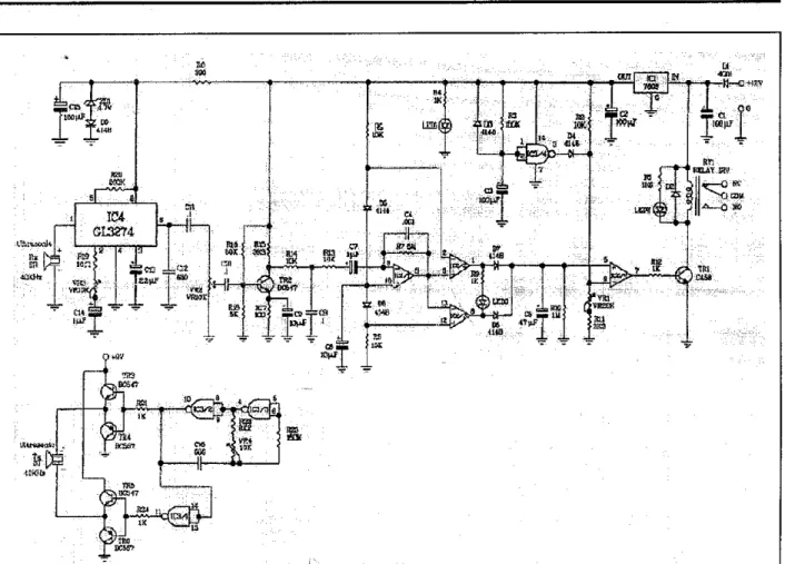
Shown below is the schematic diagram of Ultrasonic Sensor circuit for the navigation aid.
Figure 3.2: the schematic diagram of Ultrasonic Sensor circuit
The Ultrasonic Sensor circuit has divided into two parts:
o Transmitter
IC3/2 and IC3/3 is the circuit to make oscillate the ultrasonic frequency of 40KHz. The
Oscillation's operation is settled on R22, R23, C16 and VR4. The frequency of the
ultrasonic must be adjusted to the resonant frequency of the ultrasonic sensor. Therefore, the resistor (R) is made to be able to adjust the oscillation frequency by making it the variable resistor (VR). The ultrasonic of 40 KHz is amplified before sent out to thetransmitter.
o Receiver
The detection is done to detect the received ultrasonic signal. The detection circuit is the circuit which detects the ultrasonic which returned from the object. The output of the detection circuit is detected using the comparator. At the circuit this time, the operational amplifier (IC2/2 and IC2/3) of the single power supply is used instead of the comparator.
The positive input is detected by IC2/2 and IC2/3 detects the negative input. The operational amplifier amplifies and outputs the difference between the positive input and the negative input.
In case of the operational amplifier which doesn't have the negative feedback, at a little input voltage, the output becomes the saturation state. Generally, the operational amplifier has tens of thousands of times of mu factors. So, when the positive input becomes higher a little than the negative input, the difference is tens of thousands of times amplified and the output becomes the same as the power supply almost. (It is the saturation state) Oppositely, when the positive input becomes lower a little than the negative input, the difference is tens of thousands of times amplified and the output becomes 0 V almost.(It is in the OFF condition) This operation is the same as the operation of the comparator.
• Hardware Specification
The design of the stick that uses to install the circuit should also take into consideration in order to produce the most suitable equipment for the blind. Therefore the important specifications which contribute to a good design are described below:
25
o Well Build
The stick should be durable enough to tolerate the shake while the user pushes the stick
on the ground or hit the surrounding obstacles. Especially the sensor circuit places at the
end of the stick which should be covered with a good quality box so that it will not break down when it crashes with the objects.o Comfortable
The vital features of the stick which designer should think about are the weight of the stick and the simplicity of use. It is much easier for the user to keep or to carry the stick when it is extendible and light weight so that it provides the user with ease of use and the blind does not feel any difficulties to bring the stick along. Another additional feature of this stick is 'shoulder-strap' which makes it more convenience for user to carry the stick by slinging over the shoulder or at the back.
o Turn Around Wheel
For the most effective detection of the sensor, the user should be able to move or swing the stick as broad as possible. Normally the blind swings the stick around to observe the surrounding obstacles for this reason the wheels which put at the end of the stick should turn around for 360 degree to allow the user to navigate the environment effectively by covering more area for the sensor to detect the obstacles.
o Stand Able
The stick also designs to be able to stand alone. There is sometime when the user needs to rest the stick or leave it alone without holding it all the time. So a good design and right balance could make the stick stand able and that offer more benefit to the user in
terms of convenience.
3.2.4 Implementation
The final phase is the implementation phase. In this phase, the circuit development is adopted. This will take quite some time as the building circuit takes place. Also, testing will be conducted to test the system's performance in terms of usability and reliability.
Finally, the system will be assessed and the study of the user acceptance will be made
after the system is completed and tested.3.3 Development Tools
3.3.1 Tools/Equipment Required
These are the tools that are used throughout the project:
NO ELEMENTS TOOLS
1 Documentation • Microsoft Word
• Microsoft Power Point
2 Hardware • Stick
• Ultrasound Transmitter 40 KHz
• Receiver
• CD4093BE Datasheet
• Buzzer
- Battery 12VDC
Table 4: Tools and Utilities
27
CHAPTER 4
RESULTS AND DISCUSSION
4.1 Data & Gathering Analysis
4.1.1 The navigation aid system in supporting blindness
The navigation aid is another way of resolving consequences of blindness problem. It has the potential to support the blinds to live on their own. In other word, one of the main problem of the blind is discouraged to life with normal people especially blind who was blind later because of the effected from some other disease and did not get a proper treatment which lead to permanent blind so that, the navigation aid should be a useful solution to solve this problem since it assists the blind to be able to find the way on his/her own without help from others.
By the interview that have been conducted at Songkhla Association of the Blind (Appendix D), it can said that the equipment which guide the blind to navigate such as stick, become very important for the blind. Most of the blind uses stick to explore the way of the obstacle in their environment. By this fact the navigation aid will enhance the navigated capability of the blind by determining the distance and location of the object/obstacle more accurate.
Result and discussion focus on the studies that have been done in order to proceed with the design phase in second part of this project. A pre-survey has been conducted to see
the respond from the targeted user. Most of the potential user wanted the navigation aid
system to be implemented in order to make their life more qualitative. (E.g. able to travel or cross the road by themselves)
10%
• Accepted
• Unaccepted
90%
Figure 4.1: Response blind about to implement a navigation aid
Based on figure 4.1.1, most of blind at Songkhla Association of the Blind would like if the navigation aid system to be implementing.
In order to implement a navigation aid there are 2 main point are taken into
consideration:
• The appropriateness of the device with the blind people
o Design
The design of the device should contribute a comfortable to the user and should not barricade the sensory perception of the user such as, some blind unable to walk if carry the umbrella, some blind can not walk straight when wear the glasses. The most preferable design is to equip with the stick because it make the user more confidant with the result generated from device since the user get familiar with the stick as equipment to explore the obstacles. The device also should design to make it easy and convenient for
the user to carry for example the stick should be able to fold so the user can bring it
anywhere easily.29
system to be implemented in order to make their life more qualitative. (E.g. able to travel
or cross the road by themselves)
10% 90%
Figure 4.1: Response blind aboutto implement a navigation aid
Based on figure 4.1.1, most of blind at Songkhla Association of the Blind would like if the navigation aid system to be implementing.
In order to implement a navigation aid there are 2 main point are taken into
consideration:
• The appropriateness of the device with the blind people o Design
The design of the device should contribute a comfortable to the user and should not barricade the sensory perception of the user such as, some blind unable to walk if carry the umbrella, some blind can not walk straight when wear the glasses. The most preferable design is to equip with the stick because it make the user more confidant with the result generated from device since the user get familiar with the stick as equipment to explore the obstacles. The device also should design to make it easy and convenient for the user to carry for example the stick should be able to fold so the user can bring it anywhere easily.
o Price
Most of the blind get low income, visually impaired make blind face many difficulties to work as normal people. Therefore the price of the device should not be as cheap as possible to purchase. However the quality of the product should be maintained.
• The usage of the device should not be too complicated to learn
The developer should consider ability of the blind to apply the device, visually impaired make the blind to depend less on visual system and utilize the auditory and other sensory system more. So the developer should not over look this important factor to come out with uncomplicated usage which is easy to learn by the blind. The user should learn how to use the device correctly for the most usefulness, training program should be provided to coach the users to use the device and make them get use to with a new device.
4.2 Discussion
4.2.1 Evaluation
Throughout the research, it is finding that the use of Ultrasonic Sensor to develop a navigation aid for blind people can be executed. However, each area needs to be research in order to fully understand the concept and how to integrate it with the real application.
To verify the performance of the device, there are three types of test were conducted. In the following is briefly introducing some measurement results obtained with the experimental device:
• User Acceptance test
o Abstract:
The test was conducted by asking 30 samples to use the experimental device and walk around unfamiliar environment. The device was successfully been tested however there are some errors found during the experiment hence it could leads to further research for the improvement.
30
o Objective:
To verify user acceptance in terms of accuracy and usage of the device.
o Experimental Procedurals:
The samples were asked to close both eyes.
a) The samples were asked to test the experimental device.
b) The samples were brought to unfamiliar place which is an open area.
c) The samples were asked to walk around to navigate the environment and at the same time they also need to avoid the objects which obstruct along the way.
d) The samples were asked to evaluate the satisfaction of the experimental device in terms of accuracy and usage.
o Result:
20%
o Accepted
• Unaccepted
80%
Figure 4.2: User acceptance on using a navigation aid
Based on Figure 4.2.1(a), shows that 80% of the sample satisfies with the performance of the navigation aid which could help them to avoid the obstacles accurately. On the other hand 20% of the sample suggests that the device should provide more feature which could help them to localize the object easier.
o Discussion:
100%
90%
80%
70%
60%
50%
40%
30%
20%
10%
0%
Comparative Study on
User acceptance on using navigation
Before, 90%
Alter, 80%
HSf
895
TPjf¥ft
After, 20%
Before, 10%
1 WSS30V.
Accepted Unaccepted
• Before!
mAfter j
Figure 4.3: User acceptance on using a navigation aid
Based on Figure 4.2.1(b), comparing study on users' respond about a navigation aid before (pre-survey) and after (post-survey) implementing. It shows that the acceptances from user were decreased as there are comments on accuracy issue.
Although ultrasonic sensor can detect the object well in several conditions but if the surface of the object to be detected is poorly reflecting so the ultrasonic sensor will not be able to detect such object unless for shorter distance. This could lead to further study on the solution to improve the accuracy issues of ultrasonic
sensor.
32
For the effective testing result, the test should conduct with the blind at Songkhla Association of the Blind (Thailand) who has been selected to be a focus group of user but there are several factors that create difficulty to reach this group of
people. Therefore the test was conducted with a limitation on the quality sample.
The samples used in this experiment are normal person who was asked to close the eyes both sides in stead of using a real blind person. Unlike blind person,
normal person is not getting use to with how to use to stick as guidance.• Usability test
o Abstract:
The usability test was conducted by verifying the device focus on the ability to detect objects in dissimilar situations. The out come of the experimentproved that ultrasonic sensor is a powerful tool to localize obstacles and avoid them in certain
conditions.
o Objective:
To verify the ability of the device to detect the object in different circumstances.
o Experimental Procedurals:
The samples were asked to use the experimental device as guidance to avoid the
obstacles in different situations as below:
a) Moving objects such as walking people, walking animal, driving vehicle, etc.
b) Still objects
c) Objects locate between 0.1-1 Meter ahead d) Raining condition
e) Hanging obj ects
j) Different level area such as stair, hole, sidewalk edges, etc.
o Result:
a) Moving objects
43.33%
17%
33.33%
;• No detection
|• Inaccurate
;n Hardly accurate
!D Accurate
;• Very accurate
Scale used:
1 2 3 4
No Inaccurate Hardly Accurate Very
Detection Accurate Accurate
Figure 4.4: Usability test on moving objects
34
b) Still objects
26.67%
66.67%
m No detection
• Inaccurate
• Hardly accurate
D Accurate
• Very accurate
Scale used:
1 2 3 \
No Inaccurate Hardly Accurate Very
Detection Accurate Accurate
Figure 4.5: Usability test on still objects
c) Distance 0.1-1 Meter
3% 1%
w"
D No detection
• Inaccurate
• Hardly accurate
D Accurate
• Very accurate
50.00%
Scale used:
1 2 3 \
No Inaccurate Hardly Accurate Very
Detection Accurate Accurate
Figure 4.6: Usability test for distance between 0.1-1 Meters
36
d) Raining condition
26.67
Scale used:
10%
56.67%
m No detection
• Inaccurate
D Hardly accurate
• Accurate
• Very accurate
No Inaccurate Hardly Accurate Very
Detection Accurate Accurate
Figure 4.7: Usability test on raining condition
e) Hanging objects
For hanging object, the device can not detect such object because there is an only one sensor place at the end of the stick. Therefore the sensor can not detect the object which is hanging or placing farther than its beam spread.
f) Different level area
/-0.00%
6.67%
\ 30%
0 No detection
\
• InaccurateD Hardly accurate
^^H^S^mto' D Accurate
A
47%^
• Very accurate
-^^ \
\
17%
Scale used:
1 2 3 i
1
No Inaccurate Hardly Accurate Very
Detection Accurate Accurate
Figure 4.8: Usability test on different level area
38
The Table shown below concludes the results from six situations where the
navigation aid function in vary.
Ability to detect objects
Situation Result
Moving objects Very accurate
Still objects Very accurate
Distance 0.1-1 Meter Accurate
Raining condition Accurate
Hanging objects No detecting
Different level area Hardly accurate
Table 5: Result of usability test
Based on the Table 5, the results prove that a navigation aid is able to execute accurately in most of the provided situations however there are some certain circumstances whereby issue the problem to the performance of the ultrasonic
sensor.
o Discussion:
The ultrasonic sensor is an effective tool to detect objects in many different conditions. Nevertheless the ultrasonic sensor has also some limitation related to
echo detection likes attenuation and beam spreading, presence of noise and interference, sensitivity to temperature and humidity, poor resolution.
• Reliability test
o Abstract:
To test the reliability of ultrasonic sensor detection, the experiment was designed to apply angle of the sensor as a variable. At the end of the experiment, it was found that an angle of sensor is one of the important factors which affect the
![Table 2: Where it detects [12]](https://thumb-ap.123doks.com/thumbv2/azpdforg/10376106.0/21.829.25.764.183.480/table-2-where-it-detects-12.webp)
![Table 3: Ability to detect objects [12]](https://thumb-ap.123doks.com/thumbv2/azpdforg/10376106.0/22.829.61.704.233.518/table-3-ability-to-detect-objects-12.webp)