Speed Control ofln-Wbeel Brusbless Motor For
Hybrid
ElectricVehiCle
By
Mohd Alwi Bin Mohd Nadzir
Final Report submitted in partial fulfillment of the requirements for
Bachelor of Engineering (Hons) (Electric!ll & Electronics Engineering)
May 2011
Universiti Teknologi PETRONAS Ban dar Seri Iskandar,
31750 Tronoh, Perak Darul Ridzuan
Approved:
CERTIFICATION OF APPROVAL .
Speed Control ofln-Wheel Brushless Motor For Hybrid Electric Vehicle
By
Mohd Alwi Bin Mohd Nadzir
Final report submitted in partial fulfilment of the requirements for Degree Bachelor of Engineering (Hons) (Electrical & Electronics Engineering)
· n bin Mohd Zulkifli Project Supervisor
Universiti Teknologi PETRONAS Tronoh, Perak
May 2011
CERTIFICATION OF ORIGINALITY
This is to certify that I am responsible for the work submitted in this project, that the original work is my own except as specified in the references and acknowledgements, and that the original work contained herein have not been undertaken or done by Unspecified solirces or persons.
I BIN MOHD NADZIR
ABSTRACT
This report, Speed Control of In-Wheel Brushless Motor for Hybrid Electric Vehicle, presents the development of a study which implements closed- loop speed control of a 3-phase, brushless, permanent-magnet in-wheel motor for a hybrid electric vehicle using external controller and motor drive. An in-wheel motor can convert an ordinary car into a split-parallel type hybrid electric vehicle by replacing the rear wheels with in-wheel motors. The purpose of conducting this project is to investigate the a method to control the speed of the motor with conventional PID , using ari off-the-shelf motor drive from Kelly Controller and NI Compact Rio as the controller. Furthermore, this project also present a study and analysis on the characteristics of the Brushless Direct Current (BLDC) motor and a study about the behavior of an additional control strategy which is speed control. Data and results will be obtained from field experiments ori the actual motor in the lab. A Brushless Direct Current motor uses electronic commutation for basic operation. So, the basic brushless motor drive system will perform the commutation to start the brushless motor and the wheels of the car will also rotate.
The control system
will
be implemented using NI LAb VIEW Real-Titne software.TABLE OF CONTENTS
AiJstRi\ct ... .i
LIST OF FIGURES ... .iv
LIST OF TABLES ... .iv
CHAPTER 1: INTRODUCTION ... l 1.1 Background ofStudy ... l 1.2 Problem Statement. ... .3
1.3 Objectives and Scope of Study ... .4
CHAPTER 2: LITERATURE REVIEW ... .5
2.1 Brushless DC Motor ... 5
2.2 Six-Step Commutation ... 7
2.3 System Block Diagram ... 9
2.4 Advantages of Hybrid Car ... lO CHAPTER 3: METHODOLOGY ... ll 3.1 Procedure and Identification ... :! 1
3.2 Tools and Equipments ... l4 CHAPTER 4: RESULTS AND DISCUSSION ... 15
4.1 Overall Brushless DC Motor Drive ... IS 4.1.1 Hardware Connection by using Kelly Controller .... .16
4.2 No-Load Test. ... 22
4.3 Analysis on current, voltage and hall sensor position profile by using Pasco ... . 24 4.4 Analysis of output voltage and current form by using
4.5 Connecting Brushless DC Motor with Electrocraft ... 35
4.6 Speed Control ofBLDC Motor by using LabVIEW Software ... 36
CHAPTER 5: CONCLUSION AND RECOMMENDATION ... .40
5.1 Conclusion ... 40
5.2 Recommendations ... .40
REFERENCES ... ... .41
APPENDICES ... .42
APPENDIX A APPENDIXB APPENDIXC Experiment ofBrushless Motor ... .42
Gantt Chart FYPI and FYP2 ... .43
Kelly Controller's Circuit Diagrarn ... .45
Figure 1 Figure 2 Figure 3 Figure 4 Figure 5 Figure 6 Figure 7 Figure 8 Figure 9 Figure 10 Figure 11 Figure 12 Figure 13 Figure 14 Figure 15 Figure 16 Figure 17 Figure 18 Figure 19 Figure 20 Figure 21 Figure 22 Figure 23 Figure 24 Figure 25
LIST OF FIGURES
The four poles on the stator of a two-phase BLDC motor ... 2
Hall Sensors ... 2
Brushless DC Motor Internal Diagram ... 6
Six-step Method for operating the motor. ... 8
Block Diagram Speed Controller. ... 9
Flow Chart ofProject. ... .12
Flow Chart ofFYPl and FYP2 ... .13
Brushless DC Motor Kelly Motor Drive ... .l3 RS232 Cable ... l4 Brushless Motor Drive Systems ... 15
Hardware Connection by using Kelly Controller ... .l6 Connections between Kelly Controller and the DC Power Supply .. 17
Connections at the behind of the Kelly Controller ... .18
Configure setting in the Kelly Controller ... 18
DC Power Supply set to 48Volts ... 19
Connections between Motor, Wheel, Brake and Throttle ... 20
Connections between DC Current Meter with Oscilloscope Probe .. 21
Oscilloscope graph oUtput for current and voltage at the Phase A ... 21
Graph of Current versus Speed ... 23
Connections between Pasco, Kelly Controller and PC ... 24
Voltage signal at phase A with 100% of throttle position ... 25
Voltage signal at phase A with 50% of throttle position ... 26
Voltage signal at phase A with 24V DC Supply ... 27
Voltage signal at phase A with 48V DC Supply ... 28
Output of Hall A at 50% of throttle position ... 29
Figure 27 Figure 28 Figure 29 Figure 30 Figure 31 Figure 32 Figure 33 Figure 34 Figure 35 Figure 36 Figure 37 Figure 38
Connection DC Current Clamp with oscilloscope ... 32
Output voltage at Phase A, B and C ... .33
Overlap output voltage at Phase A, B and C ... .33
Output voltage and current at Phase A ... .33
Connections at Electrocraft ... .35
Connection between Electrocraft with BLDC motor ... 35
Front Panel ofPWM duty cycle for motor speed contro1... ... .36
Code of the Lab VIEW program(block diagram) ... .37
Hall Sensor Output with Noise Interference ... 3 7 RC Lowpass filter circuit. ... .3 8 RC Lowpass filter ... .38
Before and After Applying RC Lowpass Filter ... 39
Table 1 Table2 Table 3
LIST OF TABLES
Comparison ofBrushless DC Motor and Conventional Motor ... 6 Tools and Equipments ... l4 Result for No Load Test ... .22
CHAPTERl
INTRODUCTION
1.1. Background of Study
Brushle$s DG motors have been replacing brush-type motors in machine tool and robotics applications over the few years. The well-known advantages of brusbless over brush motors include improved reliability, higher power to weight ratios, and an overall better dynamic performance. Nowadays, Brushless DC motor has become the most compatible motor and already applied in the existing applications such as appliances, automotive, helicopter, medical, industrial automotive equipment and even in aerospace sector. A BLDC motor has permanent magnets which rotate and a fixed armature, eliminating the problems of connecting current to the moving armature. An intelligent electronic controller replaces the commutator assembly of the brushed DC motor, which continually switches the phase to the windings to keep the motor turning.
BLDC motor have many advantages compared to brushes DC motor such as higher efficiency, noiseless operation, high speed ranges, better torque speed characteristics and more compact construction. In addition, BLDC motors are useful and good in converting electric power into mechanical power than brushed DC motors. Furthermore, these advantages are "due to the absence of electrical and friction loss due to brushes. BLDC motors and high-quality brushed motors are comparable in efficiency under high mechanical loads." [1]
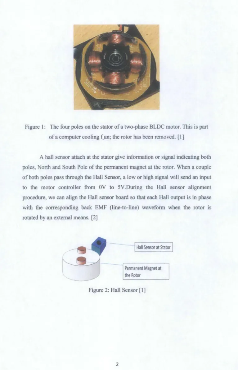
Figure 1: The four poles on the stator of a two-phase BLOC motor. This is part of a computer cooling f_an; the rotor has been removed. [1]
A hall sensor attach at the stator give information or signal indicating both poles, North and South Pole of the permanent magnet at the rotor. When a couple of both poles pass through the Hall Sensor, a low or high signal will send an input to the motor controller from OV to 5V.During the Hall sensor alignment procedure, we can align the Hall sensor board so that each Hall output is in phase with the corresponding back EMF (line-to-line) waveform when the rotor is rotated by an external means. [2]
--
Hall Sensor at StatorParmanent Magnet at the Rotor
Figure 2: Hall Sensor (1]
1.2. Problem Statement
There are actually two main methods in order to control BLDC motor which is sensor and sensorless control unit. In this project, the sensor method is used.
MOSFETs or IGBTs act as switches that will control motor. MOSFETs are preferred in a high-frequency applications (>200 kHz), wide load variations, long duty cycles, low-voltage applications (<250V) and less that 500W output power. While IGBTs are preferred at low-duty cycle, low-frequency (<20kHz), narrow load variations, high-voltage applications (> 1 OOOV), operation at high junction temperature is allowed(> l00°C) and more than 5kW output power.
BLDC is powered by direct current and uses electronic commutation to operate. A hybrid vehicle uses an electric motor to move the vehicle. In order to move the vehicle, a speed controller is needed to control the speed of the motor, so that finally, the speed ofthe vehicle can be controlled.
So, a study is required to implement closed-loop speed control of a 3- phase, brushless, permanent magnet in-wheel motor for a hybrid electric vehicle using external controller and motor drive. A prototype model of in-wheel BLDC motor is being constrUcted at UTP Automotive Research Center. This prototype will be used for this project.
1.3. Objectives and Scope of Study
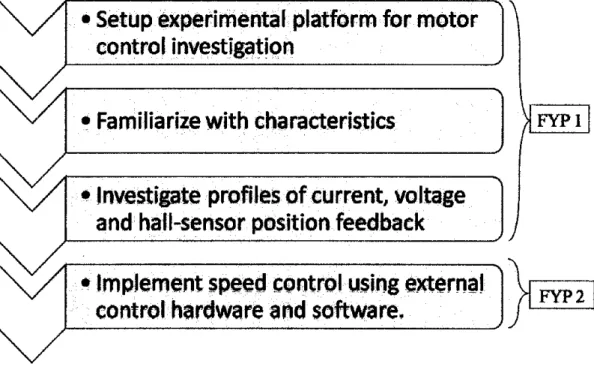
The main objectives of this project are:
1. To setup experimental platform for motor control hivestigatiori usmg in-wheel brushless motor and off-the-shelf controller.
2. To familiarize with characteristics of brushless DC motor & motor speed control
3. To mvestigate profiles of current. voltage and hall-sensor position feedback for various control inputs
4. To implement speed control using external control hardware (NI CompactRIO) and Lab VIEW software.
5. To study motor control with PID
The scopes of study in this project are:
1) Installing the hardware and setup the connection for both hardware and software between the brushless de motor, controller unit and the hall sensor 2) A lot of field experimentation, testing and being able to understand the
characteristics ofBrushless DC Motor.
3) Understand the method to control the speed of the Brushless DC Motor.
CHAPTER2
LITERATURE REVIEW 2,1 Bru~bless DC Motor
A Brushless DC motor has more advantages than brushes DC motor.A BLDC motor has permanent magnets which rotate and a fixed armature, eliminating the problems of connecting current to the moving armature. "BLDC motor has permanent magnets which rotate and a fixed armature, eliminating the problems of connecting current to the moving armature. BLDC motors offer several advantages over brushed DC motors, including more torque per weight and efficiency, reliability, reduced noise, longer lifetime (no brush and commutator erosion), elimination of ionizing sparks from the commutator, more power, and overall reduction of electromagnetic interference (EMI)." [3]
BLDC motors are useful and good in converting electric power into mechanical power than brushed DC motors. Wiring consists of four connections, namely A, B, C and Neutral/Common and every phase are divided into two equally separated windings. "Six electrical commutations written in the schematic diagram allows one full rotation ()fBLDC motor be driven in stepping mode. " [7]
The driving method resembles method of driving a stepper motor.
Table 1: Comparison ofBrushless DC Motor and conventional motor. [3]
Aspects Conventional Motor Brushless DC Motor Mechanical structure Field magnets on the Field magnets on the
stator rotor
Like AC synchronous motor
Distinctive Features Quick Response and Long Lasting Excellent Controllability Easy Maintenance
Wingding Connections Ring Connection : Delta Star or Delta connected three-phase connection Normal: Y -connected three-phase ending with grounded neutral point.
Commutation Method Mechanical contact Electronic switching Between Brushes arid llsing fuiiisiSt()fs
commutator
Detecting Method Of Automatically detected Hall element, optical
Rotor's Position by brushes encoder
Reversing Method By a reverse of terminal Rearranging logic
voltage sequencer
Figure 3: Brushless DC Motor lritemal Diagram [3]
2.2 Six-step Commutation
In brushless DC Motor speed control, 120-degree modulation and a six•
step method for operating the motor, as well as how the modulation can be implemented using hall sensors and back-emf signals. A six-step commutation sequence is used to steer the current and produce torque. The sequence starts with the initial position of the rotor aligned properly at 0 degrees. "Power at the coils U+ and V" is tunJ.ed ()!1. This excitation creates a magnetic field so that the rotor turns in the intended direction-towards the 60 degree position. When this position is reached, V- is turned off and W- is turned on. Because U+ is still on, the U+ and W- coils are excited, and torque continues in the same direction." [5]
When the rotor reaches the 120-degree position, U+ is switched off and V+ is switched on. W- is still on and so the V+ and W- excitation continues to produce torque in the same direction. At the 180-degree position, W- is turned off and U- is turned on, while V+ is kept on. At 240 degrees, V+ is turned off and W+ is turned on, with U-kept on. At 300 degrees, U- is turned off and V-is turned on, and W+ is kept on. Finally, when the rotor completes a 360-degree rotation, W+ is turned off and U+ is turned on, with V- kept on. Thus, we are "back to the original state or step I. Each phase voltage at a time takes one of three states - positive, negative, or floats. One advantage of this relation is that during the Hall sensor alignment procedure, we can align the Hall sensor board so that each Hall output is in phase with the corresponding back emf (line to-line) waveform when the rotor is rotated by an external means."[8]
Hl H2 H3
(a) Hall <;en>ot· ontpnt>.
·va I 1 ---+-l--~~--~~---L-~--~
v'b i I
I I
Vc I I
(b') 6->tep phase voltage'
~---~-::-=l~-~-~1-~ _l _____ /r--- -
.~- ·--... _ ;
(c) Bad; etnf ,-oltage wavefonn
Figure 4: Six-step method for operating the motor [8]
2.3 System Block Diagram
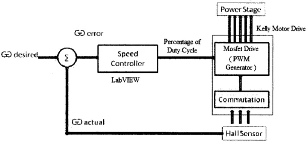
Figure 5 shows the block diagram of the speed controller in the system.
Tachometer, speed encoder or hall sensor will detect the speed of the motor and this element will give a feedback to the speed controller which will calculate if there any error. This speed controller controls the speed of the motor by either increasing or decreasing the applied voltage to the motor. The technique used to vary the voltage applied to motor by Pulse Width Modulation (PWM). The PWM will control the switch ofMOSFET in the motor drive.
.d'
@error Kelly' Motor Drive
Percentage of
@desired Duty Cycle Mosfet Drive
2 Speed (PWM
Controller
Generator)
Lab VIEW
Commtllat:icm
• • •
@actual r
!_1_1 ____ ]
Hall Sensor
Figure 5: Block Diagram of Speed Controller
PI speed controller will be implemented to the speed controller. The difference between the actual and the required speed is input to the PI controller and based on this difference, the PI controller controls the duty cycle of PWM pulses , which corresponds to the voltage llmplitllde required to keep the req\lired speed.
2.4 Advantages of Hybrid Car
Hybrids merge clean energy of the electrical motor with the power of the gas-powered engine which results into lower emissions and better mileage.
Hybrids perform at par with the normal ga-powered vehicles, if not better.
Hybrids are reliable and comfortable as any traditional car and they have a tax benefits.
The furore for hybrids loo~ bright with rapiq developments in hybrid technology to improve engine efficiency. Due to the Regenerative Braking technology, the batteries need not be charged by an external source. Special warranties are provided for the battery pack, the electric motor other costly items.
Hybrids help reduce the dependency on fossil fuels which directly affects fuel prices.
CHAPTER3 METHODOLOGY
3.1 Procedure ~nd Identific~tion
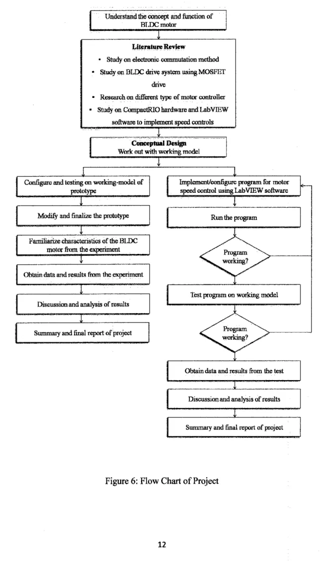
In order to achieve the objectives of the project, research and investigation will be done. The research will be done on some resources fi:oll1 the books, journal and any technical paper to obtain information that related to this project. This project will be divided by two parts which is first part is final year project 1 and another part the project will be continue for fmal year project 2. First, a study and research on how the brushless motor IS operated with the, understand the characteristics of the Brushless Motor and controller drive, and setup the connection of the hardware.
After completing install all the hardware and software and setup properly, the project will continue with field experimentation, testing and be able to understand the characteristics of Brushless DC Motor. Then, implement the speed control program that been used to control the speed of brushless motor. Speed control program will be conducting by using National Instrument I 'Compact RIO hardware & Lab View Real-Time software.
Understand the concept and function of BLOC motor
l
Literature ]leview
.
Study on eleclronic commutation method.
Study on BLOC drive system using MOSFET drive.
Research on different type of motor controller.
Study on CompactRIO hardware and Lab VIEW software to implement speed controlsl
Conceptual Design Work out with working model
t
l l
Configure and testing on working-model of Implement/configure program for motor
r-
prototype speed control nsingLabVIEW software
l
t
ModifY and finalize the prototype Ron the program
~
Familiarize characteristics of the BlDC
motor from the experiment Program
t working?
Obtain data and result• from the experiment
. -
1
Test program on working modelDiscussion and analysis of results
l
Summary and final report of project Program working?
Obtain data and results from the test
l
Discussion and analysis of results
l
Summary and finsl report of project
Figure 6: Flow Chart of Project
• Setup experimental platform for motor control investigcition
• Familiarize with characteristics
•Investigate profiles of current, voltage and hall-sensor position feedback
• Implement speed control using external ~
control hardware and software. ~
Figure 7: Flow chart ofFYPl and FYP2
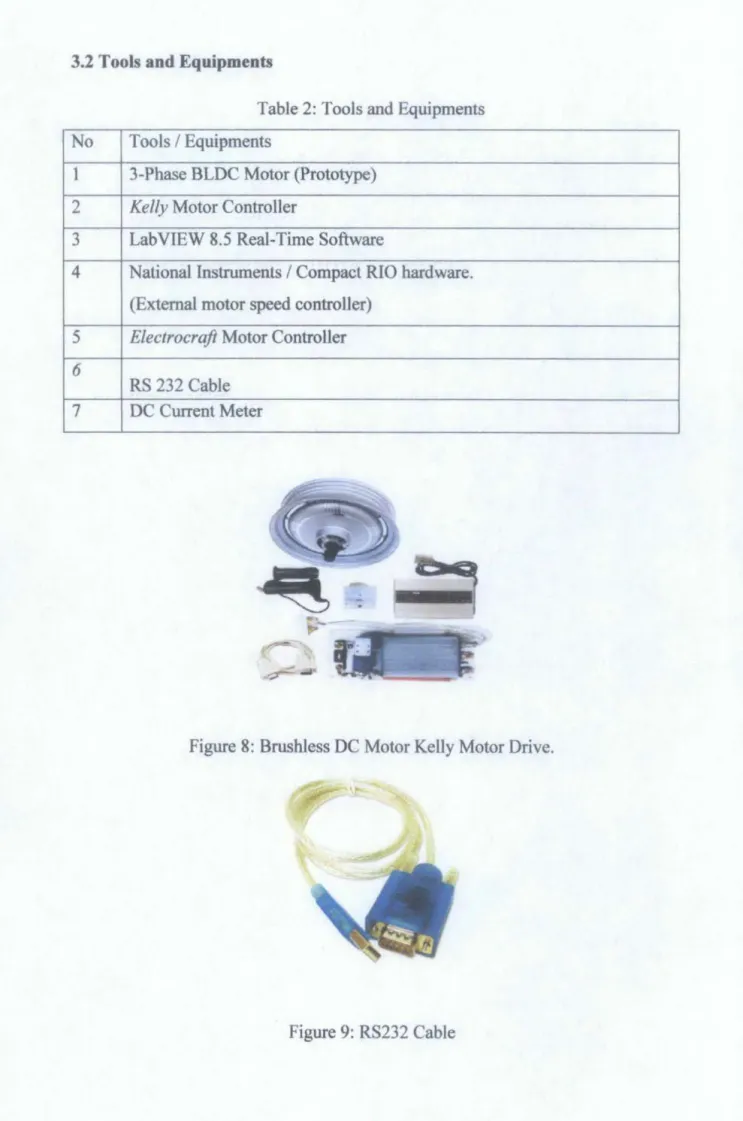
3.2 Tools and Equipments
Table 2: Tools and Equipments No Tools I Equipments
1 3-Phase BLDC Motor (Prototype) 2 Kelly Motor Controller
3 Lab VIEW 8.5 Real-Time Software
4 National Instruments I Compact RIO hardware.
(External motor speed controller) 5 Electrocraft Motor Controller 6 RS 232 Cable
7 DC Current Meter
.,
I <- .
-
-.
Figure 8: Brushless DC Motor Kelly Motor Drive .
....
CHAPTER4
RESULTS AND DISCUSSIONS
4.1 OveraU Brusbless DC Motor Drive
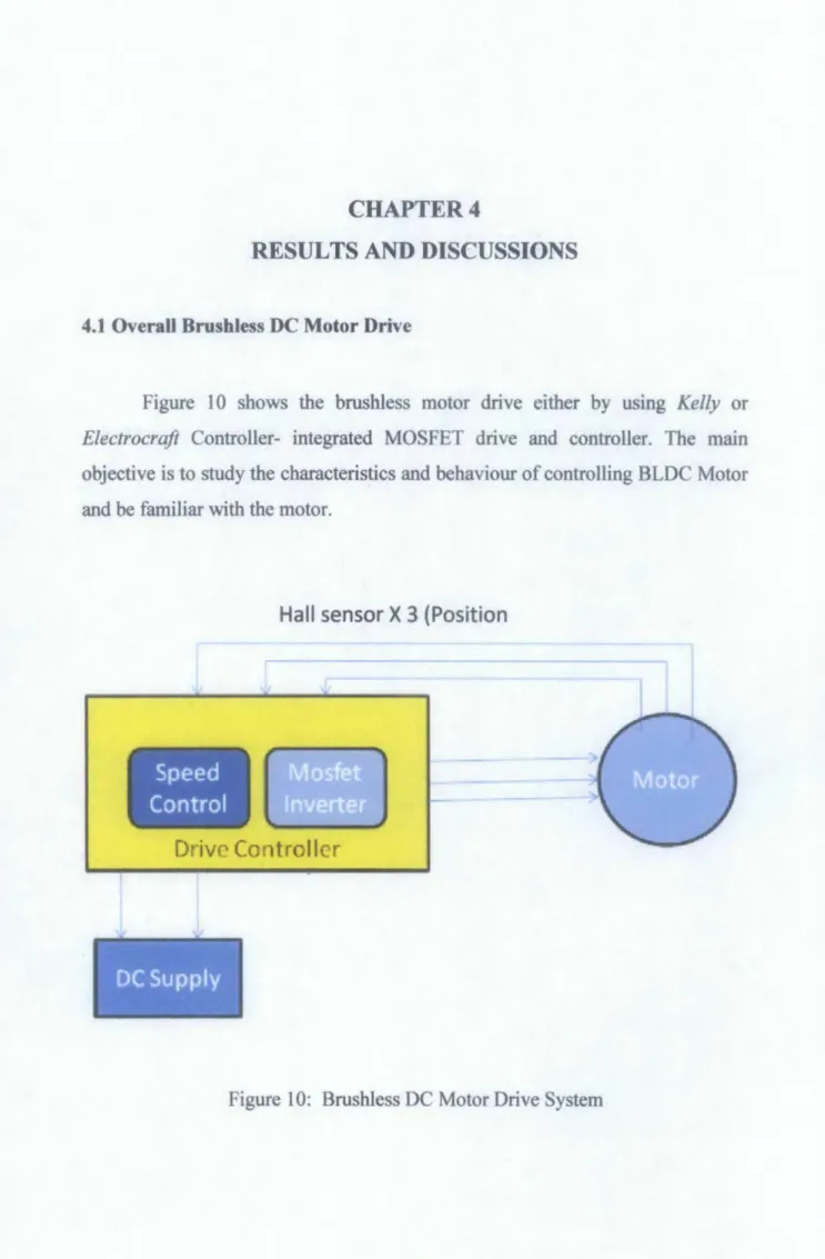
Figure 1 0 shows the brushless motor drive either by using Kelly or Electrocrafi Controller- integrated MOSFET drive and controller. The main objective is to study the characteristics and behaviour of controlling BLDC Motor and be familiar with the motor.
Speed
Control
Hall sensor X 3 (Position
Drive Controller
DC Supply
Figure 10: Brushless DC Motor Drive System
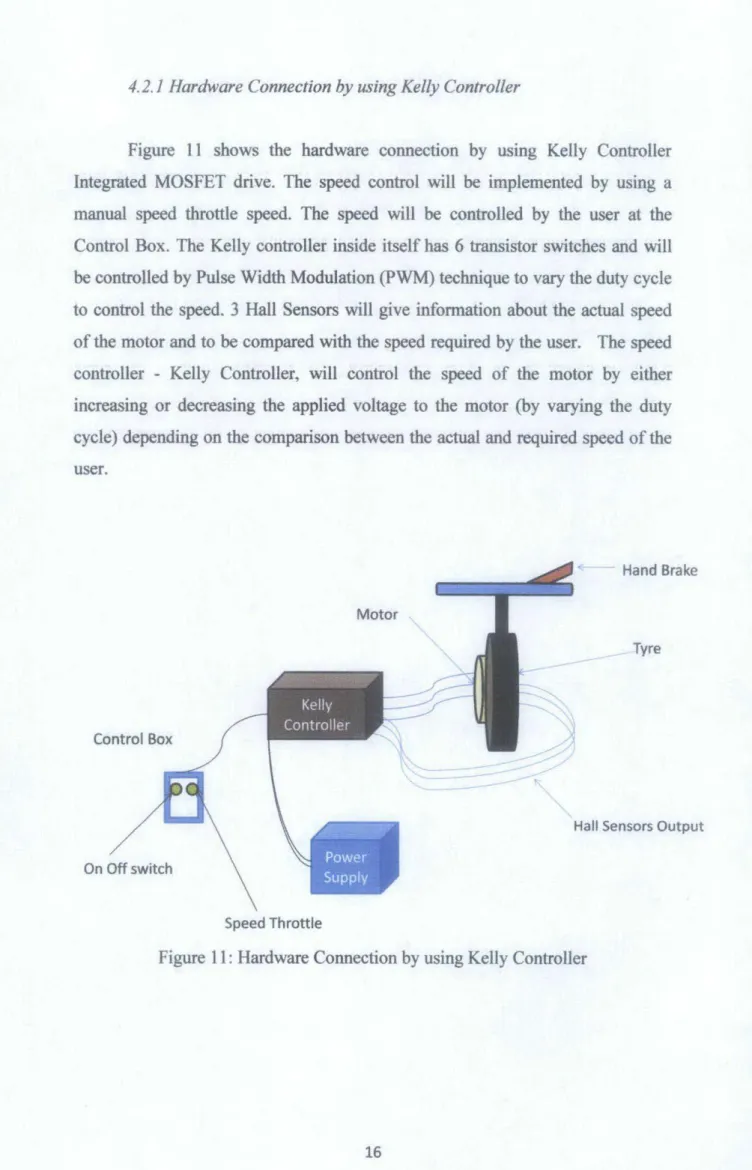
4. 2. I Hardware Connection by using Kelly Controller
Figure II shows the hardware connection by using Kelly Controller Integrated MOSFET drive. The speed control will be implemented by using a manual speed throttle speed. The speed will be controlled by the user at the Control Box. The Kelly controller inside itself has 6 transistor switches and will be controlled by Pulse Width Modulation (PWM) technique to vary the duty cycle to control the speed. 3 Hall Sensors will give information about the actual speed of the motor and to be compared with the speed required by the user. The speed controller - Kelly Controller, will control the speed of the motor by either increasing or decreasing the applied voltage to the motor (by varying the duty cycle) depending on the comparison between the actual and required speed of the user.
..,_ - Hand Brake
Motor
Tyre
Control Box
Hall Sensors Output
On Off switch
Speed Throttle
Figure li : Hardware Connection by using Kelly Controller
Figure 12: Connection between Kelly Controller and DC Power Supply
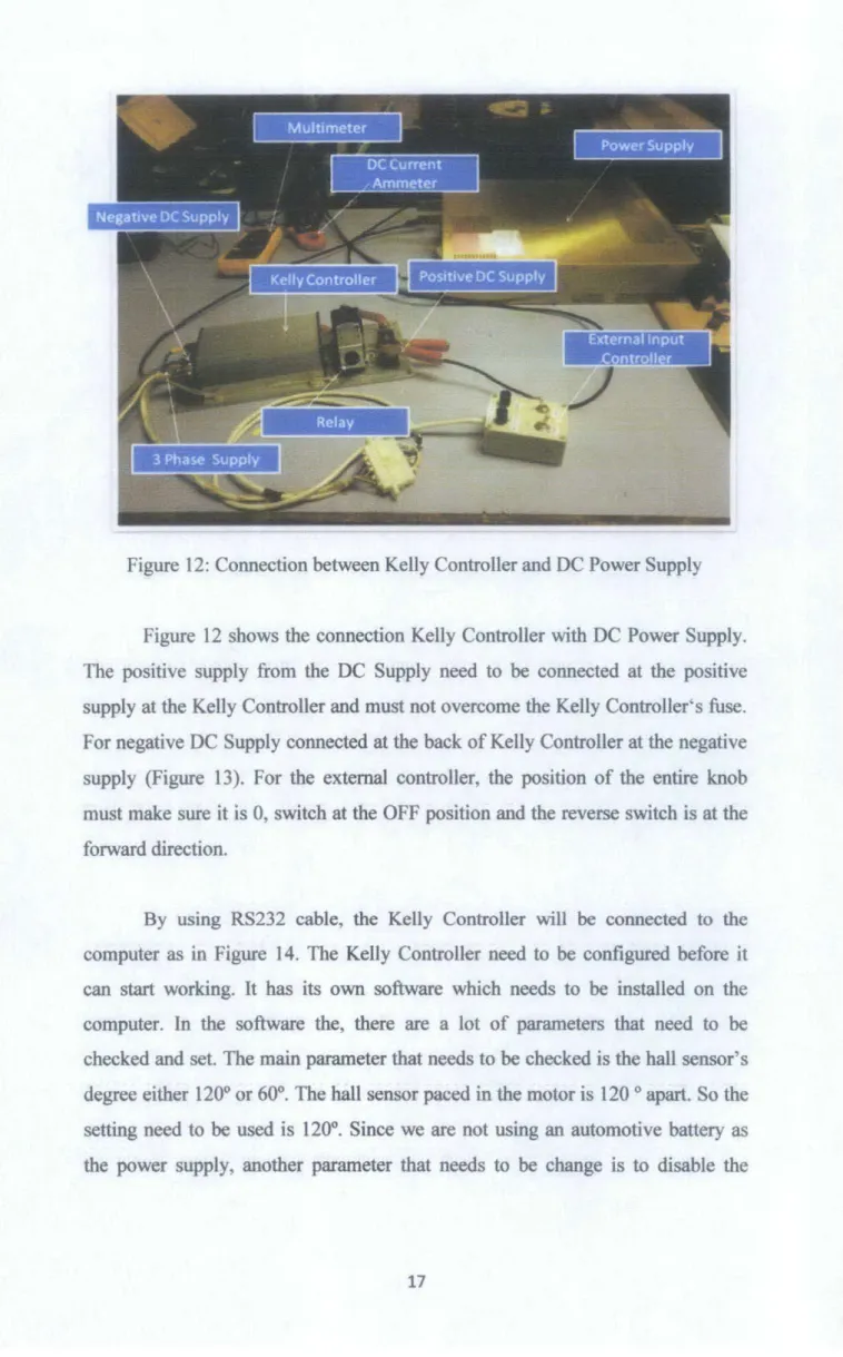
Figure 12 shows the connection Kelly Controller with DC Power Supply.
The positive supply from the DC Supply need to be connected at the positive supply at the Kelly Controller and must not overcome the Kelly Controller's fuse. For negative DC Supply connected at the back of Kelly Controller at the negative supply (Figure 13). For the external controller, the position of the entire knob must make sure it is 0, switch at the OFF position and the reverse switch is at the forward direction.
By using RS232 cable, the Kelly Controller will be connected to the computer as in Figure 14. The Kelly Controller need to be configured before it can start working. It has its own software which needs to be installed on the computer. In the software the, there are a lot of parameters that need to be checked and set. The main parameter that needs to be checked is the hall sensor's degree either 120° or 60°. The hall sensor paced in the motor is 120 o apart. So the setting need to be used is 120°. Since we are not using an automotive battery as the power supply, another parameter that needs to be change is to disable the
regenerative function because we are not going to generate power while braking since we are using DC Power Supply.
Figure 13: Connection at the back of Kelly Motor Drive
Figure 15: DC Power Supply set to 48 Volts
The DC Power Supply is capable to supply until 60V. In this test, the DC Supply is set at 48V (Figure 15). It is reasonable to set it to 48V because in the real situation, the DC Power Supply will be replaced by a car's battery which is usually 12V and if make it in series it can achieve 48V. Furthermore, 48V was more than enough to turn on the Kelly Controller's Power relay. At the current meter, the knob just need to be turned until any current value as the limit current to the controller. The current at the meter will start to increase when the motor start to move.
In Figure 16, a 3-Phase Brushless DC in-wheel motor is shown and voltage supply from the Kelly Controller has been connected. At the motor handle (Figure 16), the brake acts as the medium to supply load to the motor and can be used as the load to test the current characteristics of the motor. In addition, the handle is also included with the throttle that can adjust the speed of the motor. In
this test, this throttle is not connected as the user input to control the motor speed since we will use an external input controller.
Figure 16: Connection between Motor, Wheel, Brake and Throttle
In this project, an oscilloscope is used to capture the data and graph of the current and voltage. The DC current meter is clamped at the power supply of the DC Power Supply, and the current meter shows the current value as a voltage output as it is current transducer. So the oscilloscope shows the value of voltage which represents the current value. The other oscilloscope probes are used to check the voltage of the supply and also phase voltage.
By using the oscilloscope, a clear observation can be achieved. While increasing the throttle knob, it will increase the speed of the motor, the oscilloscope shows that the throttle acting as the switch that controls the PWM duty cycle. As we increase the throttle knob, the voltage supply to the motor for each phase will also increase accordingly and also increase the duty cycle of the
Figure 17: Connection between DC Current Meter with the Oscilloscope Probe
Figure 18: Oscilloscope graph output for current and voltage at the Phase A
4.2 No-load Test
A no-load test has been done to study the characteristic of the motor, the voltage supply and the current applied. The DC Voltage supply set to 48V and turns the current knob limit into 50%. A tachometer will capture the speed for each current level increase. Average speed of the motor running without load is shown in Table 3. Turn the throttle knob to adjust the current supply to the Kelly Controller 0.5Amp for each increase, start from OAmp to 5Amp.
From the test results, the graph of Current (Amp) versus Speed (RPM) has been obtained as in Figure 19. From the graph, current increase is directly proportional to the speed of the motor. It shows that the more current applied to the motor, the higher is the speed of the motor.
Table 3: Results for No-Load Test
Current (Amp) Speed L)
0 0
0.5 61.4
1 133.4
1.5 197.2
2 272.6
2.5 341.8
3 409.5
3.5 478.5
4 547.2
4.5 617.6
5 662.2
6
5
a:
4C( E :: c 3
Ql
...
a ...
21 0
Current (Amp) vs Speed (Volt)
0 61.4 133.4 197.2 272.6 341.8 409.5 478.5 547.2 617.6 662.2 Speed (RPM)
Figure 19: Graph of Current versus Speed
4.3 Analysis on current, voltage and hall sensor position pror.Je by using Pasco
Pasco is a data acquisition device where it can collect and upload the data of voltage, current, temperature and resistance of any electrical device. This device has its own probe connector to take any data. By using RS232 cable and USB 2.0 cable, all the data taken from Pasco can be displayed at the laptop.
Figure 20: Connection between Pasco, Kelly Controller and PC.
Pasco voltage probe can be used in order to get the output voltage of each phase. Parallel Pasco voltage probe with each output phase cable from the motor.
Series the Pasco current sensor with the 3 phase output voltage to get the current signal from each phase. Since Hall sensor output is only a 5 Volt signal, Pasco voltage probe can be used to get the Hall sensor output by parallel connection of all the Hall sensor output wires with Pasco voltage probe.
4.3.1 Analysis on the output voltage profile by varying the throttle knob
Varying the throttle knob actually varies the duty cycle of PWM signals to the transistors. PWM signal is a pulse of varying length, in effect a square wave.
Duty cycle is defined as the ratio of length of ON time of the signal to the total period of the signal. By varying the duty cycle of the PWM input signal, the motor can rotate in different speeds.
(a) Test 1 :
toN
T
)Figure 21 : Voltage signal at phase A with 1 00% of throttle position
Figure 21 shows the voltage output signal when the motor is driven at 100% throttle position, meaning the motor is driven at full speed. From the multimeter, the current at that full speed with 48V DC supply is at 8.5 Amp. For the Pasco scope output, each square division it represents 5V /div and 2ms/div, for voltage and time respectively.
•!• Time for 1 cycle
1.6 div x 2ms = 3.2 ms
•!• Frequency for 1 cycle
1 I 3.2 ms
=
312.5 Hz•!• Duty cycle = (toN ff) x 100%
= (1.4/3.6)x100%
=88%
(b) Test 2:
Figure 22: Voltage signal at phase A with 50% of throttle position
Figure 22 shows the voltage output signal when the motor is driven at the 50% throttle position, which mean the motor is driven at half-full speed. From the multimeter, the current at that speed with 48V DC supply is 4.3 Amp.
•!• Time for 1 cycle
3.0 div x 2ms = 6.0 ms
•!• Frequency for 1 cycle 1 I 3.2ms
=
166.7 Hz•!• Duty cycle = (toN ff) x 100%
= ( 1.6/3) X 100%
= 46.7%
From the above analysis, the PWM duty cycle of this controller is being
to the 50%, the duty cycle also decrease almost 50% from the full throttle's duty cycle.
4.3.2 Analysis on output voltage profile by varying the DC power supply
The main purpose of this analysis is to check the effect of varying the DC power supply to the output voltage and the PWM Duty Cycle of the motor.
(a) Test 1:
A
\J_U_V
Figure 23: Voltage signal at phase A with 24V DC Supply
Figure 23 shows the voltage output signal when the motor is driven at 100% throttle position mean the motor been driven at full speed. The DC voltage supply to the controller is set at 24 Volt. From the multimeter, the current at that full speed with 24 V DC supply is 4.3 Amp.
•!• Time for 1 cycle
3.4 div X 2ms = 6.8 ms
•!• Frequency for 1 cycle
1 I 6.8ms = 147.09 Hz
•!• Duty cycle = (toN ff) x 100%
= (2.8/3.4)x100%
= 82.3%
(b) Test 2:
A
.. ....!,.. ...
L
Figure 24: Voltage signal at phase A with 48V DC Supply
Figure 24 shows the voltage output signal when the motor is driven at the 1 00% throttle position, meaning the motor is driven at full speed. The DC voltage supply to the controller is set to 48 Volt. From the multimeter, the current at that full speed with 48 V DC supply is at 8.5 Amp. For each square division it represents 5V/div and 5ms/div.
•!• Time for 1 cycle
0.6 div X 5ms = 3 ms
•!• Frequency for 1 cycle
1/3 ms=333.3Hz
•!• Duty cycle = (toN ff) x 100%
= (0.5/0.6)x 100%
From the above analysis, at full throttle position, the PWM duty cycle of this controller is almost constant when varying the DC supply voltage. The DC supply voltage only affects the frequency to complete 1 cycle (from high peak position to another high peak position). By increasing the DC supply voltage, actually the frequency to complete 1 cycle of the output voltage is increasing proportionally. Increasing DC supply voltage from 24V to 48V will increase the frequency taken to complete 1 cycle of the output voltage.
4.3.3 Analysis on the Hall sensor profile by varying the throttle knob.
Hall sensor senses the position of the magnets in the motor and sends the logic (0-SV) signal to the controller. The output from Hall sensor is to do the commutation and as a feedback input for control the speed of BLDC motor.
Electrocraft controller itself determines the speed of the motor by using the output of Hall sensor signal. This is a closed-loop speed mode to control the speed by using the Hall sensor signals as feedback input for the speed.
(a) Test 1:
Figure 25: Output of Hall A at 50% of throttle position
Figure 25 shows the hall sensor output signal when the motor is driven at the 50% throttle position, meaning the motor is driven at half of the full speed.
The DC Voltage supply to the controller is set at 48 Volt. From the multimeter, the current at that full speed with 48 V DC supply is at 4.3 Amp.
Time for rotation = time 1 cycle X num. magnet pole
= 5ms x 20
= O.ls
Frequency (Hz) = 1 I t
=
11 O.ls= 10Hz
Speed (RPM) =Frequency (Hz) x 60 second
=10 Hzx 60s
=600rpm Speed by Tachometer= 597rpm
(b) Test 2:
rv
,..,
rv ,..., N /""' ["\. M r- I"' M,.-l.oo-- ~ 1.-J !,-, ~c_lt:..J _ _ ~ l.d
!.d _ ""
•
rv
l - ,_
2.
' ~ ~ _., 0.,.,.
r1
lnl
Figure 26: Output of Hall A at 100% of throttle position
Figure 26 shows the hall sensor output signal when the motor is driven at the 1 00% throttle position, meaning the motor is driven at full speed. The DC Voltage supply to the controller is set at 48 Volt. From the multimeter, the current at that full speed with 48 V DC supply is 8.5 Amp.
Time of one cycle = time of one division X num. division per cycle
= 3ms x 20
=0.06s Frequency (Hz) = 1/ t
= 11 0.06s
= 16.67 Hz
Speed (RPM) =Frequency (Hz) x 60 second
=16.67 Hz x 60s
=1000 rpm Speed by Tachometer= 1012 rpm
From the above analysis, at full throttle position, the motor is run at full speed and at middle throttle position (50%) the motor is run at half of full speed.
The speed can be calculated by using the output signal of the Hall sensors. From this test, speed control can be implemented by only using Hall sensors for speed measurement.
4.4 Analysis of output voltage and current form by using Oscilloscope
In brushless DC motor operation, a six-step method for operating the motor, as well as how the modulation can be implemented using hall sensors and back-emf signals. A six-step commutation sequence is used to steer the current and produce torque. There are many types of commutation such as Sinusoidal Commutation, Trapezoidal Commutation and Six-Step Commutation. The purpose of this test is to check the type of commutation used by Kelly controller and to study the current profile.
Figure 27: Connection between DC Current Clamp with oscilloscope probe.
Figure 27 show the connection between the Current Clamp and the oscilloscope probe. Parallel Oscilloscope Probe at each phase output voltage wires and clamp current meter at the each phase output voltage wires. The current meter needs to be clamped at the same direction with the current flow.
Figure 28: Output voltage at Phase A, Band C
Figure 29: Overlap output voltage at Phase A, B and C
Figure 30: Output voltage and current at Phase A
Current supply at phase A;
DC Current Meter Ratio:
lOmV= 1 Amp
Total voltage at the oscilloscope:
50 mV I div x 0.95div = 45 mV
Total current supply at phase A:
45mV=4.5 A
Figures above show that Kelly Controller uses trapezoidal six-step commutation type. Current waveform obtained by the DC Current Meter almost the same with the voltage form.
4.5 Connecting BrushJess DC Motor with Electrocraft
Another integrated MOSFET controller that is very suitable for this project is Electrocraft. This controller is very good since it can be used in the rough purpose and very suitable to be placed in the bonnet of the car. All the connection from the Kelly Controller is removed and a new connection is made for Electrocraft with Brushless DC Motor.
Figure 31: Connection at Electrocraft
Figure 32: Connection between Electrocraft with BLDC motor
4.6 Speed Control ofBLDC Motor by using Lab VIEW Software
Lab VIEW is a graphical programming environment to develop sophisticated measurement, test, and control systems using intuitive graphical icons and wires that resemble a flowchart. Designing standard Windows interfaces in Lab VIEW is straight forward. Lab VIEW components are a natural extension of the Lab VIEW Graphical Object-Oriented Programming environment interface objects that can be simply added to a block diagram.
A program is built by using the pulse width modulation (PWM) duty cycle that indicates to the voltage applied to the BLDC motor. Since the motor is directly proportional to the applied voltage, by varying the duty cycle of the PWM signal, a varying voltage can be applied to the motor. Figure 33 below shows the front panel of the PWM duty cycle control. It consists of a set of tools and objects that have code using graphical representation of function to control the front panel object.
PWM Duty Cycle
(Manual Control)
100-:
-~
10~l'O~
,... _ _ eo.;
5 so.::
-~
JO;
»-:
10~
o=
PWM Frequency
--
- c o d e~J 0
Motor Speed (RPM)
Toclr Cowd(noSec:) 0
Frequency 0
t.oop lltoetioft 0
STOP '
Figure 34 : Code of the Lab VIEW program (block diagram)
The speed of the motor can be displayed on the front panel of the Lab VIEW program. The output of the hall sensor will be connected to the NICompact RIO, and the data will be displayed at the user front panel. A very important part is to get the frequency from the hall sensor output because the frequency obtained is used to calculate the motor speed. The waveform output from Hall Sensor is not smooth and has a lot of high-frequency noise interference in the 0-5V signal. LabVIEW cannot read properly the frequency from the Hall sensor because of this high-frequency noise. The CompactRIO hardware has a very large frequency reponse bandwidth. It can detect high frequency eventhough the frequency is actually is the noise frequency.
Figure 35 :Hall Sensor Output with Noise Interference
t
Magnitude+of noise
4. 6.1 Design of a RC lowpass filter
Since Lab VIEW reads the noise as frequency change , Lab VIEW program can not display the correct speed of the motor. This problem can be solved by apllying a RC Lowpass Filter in the circuit. Connect the RC Lowpass filter circuit between the output of Hall sensor from Electrocraft and the Compact RIO controller.
R
o~.JW -c-r--...--o
vin
I
vouto~---~---o
Figure 36 : RC Lowpass filter circuit
In order to design the RC lowpass filter cicuit, the author chooses the RC lowpass cutoff fequency to be 10 kHz.
1 Cutoff frequency , fc
=
- R21t
c
Since cutoff frequency , fc
=
1OkHzSuitable Resistor , R = 160
n
Suitable Capacitor , C
=
100 nFFigure 38 : Before and After Applying RC Lowpass Filter
However, even after connecting the lowpass filter, the situation improved a little but Lab VIEW still detects some high-frequency component. Even after choosing lower values for the lowpass cut-off frequency, we still can't detect the correct frequency. Therefore, at the time this report is written, the experiment is still ongoing. The author will also try other programming method in Lab VIEW to
overcome this problem of measuring the motor speed.
CHAPTERS
CONCLUSION AND RECOMMENDATIONS
5.1 Conclusion
BLDC motor is widely used in industrial applications due to its advantages of higher efficiency compared to the conventional motor. Therefore, important to electrical engineers to study and familiarize the characteristics of this motor.
Implementation of speed control function is ongoing using software programming to achieve successful completion. Hopefully, this project will be able to contribute towards the automotive industry- specifically the hybrid electric vehicle, which is environmentally friendly.
5.2 Recommendations
A lot of experimentation needs to be completed in order to familiarize with the characteristics of brushless DC motor & motor speed control. Further investigation on the profiles of current, voltage and hall-sensor position feedback for various control inputs, is recommended
Implement speed control using external control hardware (NI CompactRIO) and LabVIEW software. In addition, study and familiarize with motor control, specifically with the PID algorithm. In the future, we should also investigate other control algorithm such as modified PID, and fuzzy logic and compare the performance between the different algorithms.
REFERENCES
[1] Brushless DC electric motor, 2010, 15 August 2010, from http://en.wikipedia.org/wiki!Bnishless _DC_ electric_ motor
[2] Brushless DC Motor Drivers, Brush DC Motor Drivers, and Stepper Motor Drivers, 2010, 15 August 2010, from
http://www.allegromicro.com/en/Products/Categories/ICs/motor.asp
[3] Electric motor, 2010, 15 August 2010, from
l:lttp:/1 en~ wikipedia.orwwik.i/electric _111otor
[4] Brushless Motors: Sensored vs. Sensorless, 2010, 15 August 2010, from http://www.teanmovak.com/tech _ info/brushless/sensor _ vs _ sensorless.html [5] Hall Effect Sensor, 2010, 15 August 2010,
http://en.wikipedia.org/wiki/ Hall effect sensor
[6] ElectroCraft Complete Power™ Drives, 2010, 15 August 2010, from http://www.electrocraft.com/products/drives/
from
[7] Mohd Farizol Fuzmi, (20 1 0). 3 Phase Brushless Permanent-Magnet Motor Control for Hybrid Electric Vehicle In-wheel Motor.UliiversityTekriologi PETRONAS, Malaysia.
[8] Daly. Ohm, Jae H. Park, About Commutation and Current Control
M~thods for Brusbl~ss Motors, Application Notes.
APPENDICES
APPENDIX A: Experiment ofBrushless Motor with Electrocraft Controller
. - . -. -..,...-....----~
Electrocraft !
- '· ~.1
NICompactRIO
APPENDIXB
GANTT CHART FYP I
Week Number 1 2 3 4 5 6 7 8 9 10 11 12 13 14
Activity
Selection of Project 26-Jut Topic
Confirmation of Project 29-Jul Topic
I • Meeting with
Supervisor !
Preliminary Research Work I
Submission of Preliminary Report Configure Connection hardware and software Familiarize with the BLOC characteristic
Submission of Progress 22-Sep
Report Seminar2
Project work continues Submission of Interim Report Final Draft Oral Presentation
GANTT CHART FYP II
Week Number 1 2 3 4 5 6 7 8 9 10 11 12 13 14
Familiarize with the 26-Jul BLDC characteristic
Experiment of BLDC 29-Jul motor
Progress Report Programming Lab VIEW
Discuss result obtain Study and analysis Draft Report
Final Report 22-Sep
Technical Report Final Report Hard Cover
Oral Presentation
J
l
'---"""'
~----
l ~~. I
li t ~~:. :_
L+.- . r-~~
~.e. From Fro,.n &de : I :
r;
--· · ·-
L,.-
- ·- -
APPENDIXC
KELLY CONTROLLER'S CIRCUIT DIAGRAM
1,--,1 .....
..
. ~"
tl""' -
~-
- ,...,..
~ __,_., .. ~
·-·
...
~
,.
..
~...
ro::>=--
1 - · :.x
... .
...
_ _
<) _r- .• COI'lnQ.eCor
I
BLOC MOTOR MOTOR
·---·
.:c:...'ft---~ I
e-~
I
I
..,. . . (.1
g.
-Or·t"O••·
···-·
-'!{"
. ..
... "! . . . .. ~ ":·~"""""
:..~~
... Q ... IJ;':Itt
,._
. .
__ . ._.,.,....,...,..~ _..,~ .. . .;..
~
~
-=-i
_I_? ---~
'lec.Tro•~• ••Y:.-hoo.,.._,r•-"••••l"'!.,.._.
••• 00'1 ~ .... . . t:~ ... Th • • • ,.,,.~,. .. ,.,.,.
,
...
.... -:~c-·~CLl.Y CQ.~TnCL-' ~ ... e.
t;.u. '"':'"
·~_...,."'_•,...·r-
KBL(>72V) Assembly Wirtng Diagram AM•sto ""'""'' ..
- ... . ,., ... ., ... , ..
,~..
t"'"'""'~VI t
·-
![Figure 3: Brushless DC Motor lritemal Diagram [3]](https://thumb-ap.123doks.com/thumbv2/azpdforg/11186074.0/15.848.114.740.101.1045/figure-3-brushless-dc-motor-lritemal-diagram-3.webp)
![Figure 4: Six-step method for operating the motor [8]](https://thumb-ap.123doks.com/thumbv2/azpdforg/11186074.0/17.846.224.660.114.658/figure-4-step-method-operating-motor-8.webp)