Portable Power Supply with Ultraeapacitor Application
by
MOHAMAD NOR AKMAL BIN ABDUL HAMID
Dissertation submitted in partial fulfilment of the requirements for the Degree
Bachelor of Engineering (Hons) (Electrical & Electronics Engineering)
JUNE2009
Universiti Teknologi PETRONAS Bandar Seri Iskandar
31750Tronoh Perak Darul Ridzuan
© Copyright 2009 By
Mohamad Nor Akmal Abdul Hamid, 2009
ACKNOWLEDGEMENTS
First and foremost, praise Allah the Almighty, who has helped and gave me courage and strength in completing the Final Year Project (FYP). Without His pennission, this FYP will not be a success.
I would like to take this opportunity to express my deepest gratitude to all parties involved in conducting this project ranging from UTP lecturers, teclmician and graduate assistants to external organizations who have put a large effort in making this project a success.
I am profoundly grateful to my supervisor, Pn. Azizan Zainal Abidin who has guided and given me the opportunity to handle the project. The compliment should also go to all Electrical and Electronics Engineering lecturers and teclmicians for bundles of information and assistance in completing this project especially to Ms. Siti Hawa and Ms. Noorsyawaliza.
I would also like to give special thanks to my parents and classmates for giving continuous support and motivation throughout completing this project. Last but not least, many thanks to others whose uame was not mentioned in this page but has in one way or another contributed to the accomplishment of this project. Thank you very much.
TABLE OF CONTENTS
ABSTRACT.
ACKNOWLEDGEMENTS.
LIST OF FIGURES . LIST OFT ABLES .
LIST OF ABBREVIATIONS CHAPTER!:
CHAPTER2:
CHAPTER3:
INTRODUCTION
1.1 Background of Study . 1.2 Problem Statement 1.3 Objectives
1.4 Scope of Study
1.4.1 Relevancy of the project 1.4.2 Feasibility of the project
LITERATURE REVIEW .
2.1 Fundantental of Solar Energy . 2.2 Photovoltaic System .
2.2.1 Working Principles 2.2.2 Materials
2.3 Charge Controller Circuit 2.4 Energy Storage Unit
2.4.1 Batteries 2.5 Ultracapacitor.
METHODOLOGY 3.1 Process Flow
3.2 Procedure Identification
v Vl lX
X
ix 1 1 1 2 2 2 2
3 3 4 4 5 8 9 9 12
14 14 15
CHAPTER4:
CHAPTERS:
REFERENCES
APPENDICES
3.3 Tools
3.3.1 Hardware 3.3.2 Software 3.4 Solar Energy . 3.5 Energy Storage Unit
RESULTS AND DISCUSSIONS 4.1 Results.
4.1.1 Photovoltaic Cell 4.1.2 Ultracapacitor .
4.1.3 Charge Controller Circuit 4.1.4 Prototype
4.2 Discussions
4.2.1 Energy Storage Unit (ESU) . 4.2.2 Loads .
CONCLUSION AND RECOMMENDATIONS 5.1 Conclusion
5.2 Recommendations
Appendix A AppendixB AppendixC
15 15 15 16 17
19 19 19 21 23 26 29 29 31
32 32 32
33
35 36 42 44
LIST OF FIGURES
Figure 1 A typical solar cell system 4
Figure 2 Basic voltage regulator block diagram 8
Figure 3 A schematic diagram of basic cell elements 9
Figure4 Project flow 14
Figure 5 Overall design system. 16
Figure 6 Polycrystaline Solar panel 19
Figure 7 Simple Charging Circuit to test the Solar Panel Output 20
Figure 8 Voltage spike from PV 21
Figure 9 Graph of ultracapacitor voltage charged with constant 5V
power source vs time . 22
Figure 10 Graph of ultracapacitor current charged with constant 5V
power source vs time . 22
Figure 11 Graph ofultracapacitor voltage discharging vs time . 23
Figure 12 Voltage Regulator circuit 24
Figure 13 Experiment nsing 5V adapter to replace Solar Panel . 25
Figure 14 Experiment to power up 5V Server Motor 25
Figure 15 Experiment to power up 3.5 V light bulb 25
Figure 16 Experiment Setup 27
Figure 17 Graph of voltage from solar panel vs time 27 Figure 18 Graph of voltage from solar panel before and after MAX712
vs time. 28
Figure 19 Graph of ultracapacitor voltage vs time 28
Figure 20 The three different ratings of ultracapacitors. 31
LIST OFT ABLES
Table 1 Distribution of Annual Solar Radiation Pattern 3 Table 2 Polycrystaline Solar Panel characteristics 20
Table 3 Experiment Result 20
Table4 Energy Storage Characteristics 30
Table 5 List of the target loads for the power supply . 31
LIST OF ABBREVIATIONS
DC Direct -current
AC Alternating-current
EWB Electronics Workbench
PV Photovoltaic
PWM Pulse-width-modulation
MPPT Maximum Power Point Tracking
ah Amp Hours
SOHIO Standard oil of Ohio
DOE Department of energy
1.1 Background of Study
CHAPTERl INTRODUCTION
Portable power supply reqmres a means of storing energy for powering applications. Energy storage is typically limited to alk:aline or rechargeable batteries. In either instance, the batteries require replacing or recharging. Applications using rechargeable batteries require a secondary set of charged batteries for when the primary set is being recharged. Therefore, in most typical applications, an investment in two rechargeable battery packs is the norm. But even this strategy is not foolproof when the user is waiting for a forgotten battery pack to recharge. Portable devices have a wide range of energy-storage needs. Portable tools have high-power, high-energy needs often necessitating hours of run time between charges, whereas some children's toys only require a few seconds of operation between charges. In many applications, alternative energy-/power-sharing strategies may be employed using a new technology called ultracapacitor.
1.2 Problem Statement
Currently, the army uses customary batteries to operate their radio during outdoor operation [1]. These batteries are heavy and bulky, which is tiresome and restricts their movement to some extent [2]. Besides, it can only support radio usage for some days and not rechargeable. Moreover, the usage of batteries nowadays have exceed it limitations and a new technology must be used to compensate the demanding of portable power supply.
1.3 Objectives
The objective of this project is to design and build a prototype of a DC portable solar-powered electrical device using uitracapacitor as energy storage unit.
1.4 Scope of Study
This project is intended to design a portable power system, focusing on the low voltage use, below I 0 V for outdoor used. The main focus is to use uitracapacitor as energy storage unit and at the same time reduce the weight of current portable power system, portability to suit users such as mobile travellers and the army.
I. 4.1 Relevancy of the Project
Based on a quick survey done during the early stage of the project, most equipment used for outdoor activities is DC type. The flexibility or option offered by the device will be very useful for this kind of usage. Other than that, similar product in the market also still using batteries as the storage medium. In addition, the project also focuses on using low-cost component to make it economical so that people can afford it.
1.4.2 Feasibility of the Project
This project is expected to be completed within the twenty-five (25) weeks time frame. The first half of the period is to explore and learn more about the solar energy, piezoelectric, photovoltaic system, ultracapacitor and each element in the system. The second half of the time frame will be used to complete and run testing of the prototype.
CHAPTER2
LITERATURE REVIEW
2.1 Fundamental of Solar Energy
Solar energy is one of the renewable energy that produces power by utilising the energy from the sun. The sun basically provides energy in two forms which are light and heat. Solar thermal using heat to produce hot fluids or air while photovoltaic is used to produced electricity.
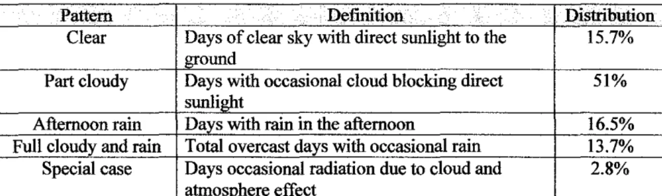
Malaysia located near to the equator, has the average daytime between 7am to 7pm and monthly average solar radiation between 4000 to 5000 W h/m2 [3]. Although the daytime is almost constant throughout the year, the global solar radiation on any particular day cannot be predicted. This is typical for any location situated in the equatorial climate. The solar radiation pattern could be classified into 5 categories (see Table 1 ). This pattern would provide a significant effect to the annual electricity production from the grid that connected to solar photovoltaic (PV) system.
Table 1: Distribution of Annual Solar Radiation Pattern [4)
Pattern Definition Distribution
Clear Days of clear sky with direct sunlight to the 15.7%
ground
Part cloudy Days with occasional cloud blocking direct 51%
sunlight
Afternoon rain Days with rain in the afternoon 16.5%
Full cloudy and rain Total overcast days with occasional rain 13.7%
Special case Days occasional radiation due to cloud and 2.8%
atmosphere effect
2.2 Photovoltaic System
The history of photovoltaic materials goes back to 1839 when Edmund Becquerel discovered the photo galvanic effect, where electric currents were produced from light induced chemical reactions. PV cell was first used in powering satellites but its application nowadays has change and growing rapidly in the power production.
2. 2.1 Working principles
When sunlight strikes a PV cell, the photons of the absorbed sunlight dislodge the electrons from the atoms of the cell. The free electrons then move through the cell, creating and filling in holes in the cell. It is movement of electrons and holes that generates electricity. The physical process in which a PV cell converts sunlight into electricity is known as the photovoltaic effect.
Normally, a single PV cell can produce up to 2 watts of power, too small for powering calculators or other equipments. In order to increase the power output, PV cells are connected together to form modules, which are further assembled into larger units called arrays. This modular nature of PV has enables designers to build PV systems with various power output for different types of application [5]. Typical solar cell system is as Figure l below.
SunN~ht
ll if;
Figure l: A typical solar cell system [ 6]
2.2.2 lkfaterials
Basically, PV cells are made of semiconductor materials. The major types of materials are crystalline and thin films. Both materials have advantage and disadvantage in terms of light absorption efficiency, energy conversion efficiency, manufacturing technology and cost of production.
Thin Film Jkfaterials
1) Amorphous Silicon ( a-Si)
Amorphous solids, like common glass, are materials whose atoms are not arranged in any particular order. They do not form crystalline structures at all, and they contain large numbers of structural and bonding defects. But they have some economic advantages over other materials that make them appealing for use in solar electric, or photovoltaic (PV), systems. In 1974, researchers began to realize that they could use amorphous silicon in PV devices by properly controlling the conditions under which it is deposited and by carefully modizying its composition. Today, amorphous silicon is common in solar- powered consumer devices that have low power requirements, such as wristwatches and calculators. Amorphous silicon absorbs solar radiation 40 times more efficiently than does single-crystal silicon, so a film only about I micrometer or one one-millionth of a meter thick can absorb 90% of the usable light energy shining on it. This is one of the major reasons that amorphous silicon could reduce the cost of photovoltaic. Other economic advantages are that it can be produced at lower temperatures and can be deposited on low-cost substrates such as plastic, glass, and metal. These characteristics make amorphous silicon the leading thin-film PV material [5].
2) Cadmium Telluride (CdTe)
CdTe is a semiconductor compound that bas high light of absorptive level. Advantage of CdTe is that it is relatively easy and cheap to manufacture by processes such as high-rate evaporation, spraying or screen printing. The disadvantage of using CdTe for PV cells is the instability and the characteristic of cadmium which is toxic [5].
3) Copper Indium Diselenide (CuinSe2 or CIS)
CIS is a polycrystalline semiconductor compound of copper, indium and selenium. Over the years, CIS has become one of the major research areas in the thin film industry. This is due to the highest "research" energy conversion efficiency of the material. Being able to deliver such high energy conversion efficiency without suffering from the outdoor degradation problem, CIS has demonstrated that thin film PV cells are a viable and competitive choice for the solar industry in the future. CIS is an efficient but complex material. Its complexity makes it difficult to manufacture. So far, CIS is not commercially available yet although Siemens Solar bas plans to commercialize CIS thin-film PV modules.[S]
Crystalline Materials
I) Single-crystal silicon
Silicon is one of the earliest materials used for photovoltaic (PV) devices. Currently, silicon is still considered as the most popular material for solar cells. Outranked only by oxygen, silicon is also the second-most abundant element in the Earth's crust. However, to be useful as a semiconductor material in solar cells, silicon must be refined to a purity of 99.9999%. A single-crystal silicon has a uniform molecular structure.
Compared to non-crystalline materials, single-crystal silicon has high uniformity which results in higher energy conversion efficiency. The higher a PV cell's conversion of energy, the more electricity it generates for a given area of exposure to the sunlight [7].
2) Polycrystalline silicon
Multicrystalline silicon devices are generally less efficient than those of single-crystal silicon, but they can be less expensive to produce. The multi crystalline silicon can be produced in a variety of ways. The most popular commercial methods involve a casting process in which molten silicon is directly cast into a mould and allowed to solidify into an ingot. The starting material can be refined lower-grade silicon, rather than the higher-grade semiconductor grade required for single-crystal material. The cooling rate is one factor that determines the final size of crystals in the ingot and the distribution of impurities. The mould is usually square, producing an ingot that can be cut and sliced into square cells that fit more compactly into a PV module [7].
3) Gallium Arsenide (GaAs)
GaAs is a compound semiconductor that made of two elements, gallium (Ga) and arsenic (As). An advantage of using GaAs is that it has high level of light absorptivity. To absorb the same amount of light, GaAs requires only a layer of a few micrometers thick while crystalline silicon requires a wafer of about 200-300 micrometers thick. GaAs also has a much higher energy conversion efficiency than crystal silicon, reaching about 25% to 30%. Its high resistance to heat makes it an ideal choice for concentrator systems in which cell temperatures are high. GaAs is also popular in space applications where strong resistance radiation damage and high cell efficiency are required. The biggest drawback of GaAs PV cells is the high cost of the single-crystal substrate that GaAs is grown on [5].
2.3 Charge controller circuit
A voltage regulator (or charge controller) is an electrical regulator designed to automatically maintain a constant voltage level. A voltage regulator monitors the battery state of charge to insure that when the battery needs charge-current it gets it, and also insecure the battery is not over-charged. Voltage regulator may use an electromechanical mechanism, or passive or active electronic components. Connecting a solar panel to a battery without a regulator seriously risks damaging the battery and potentially causing a safety concern.
Voltage regulators are rated based on the amount of amperage they can process from a solar array. If a controller is rated at 30 amps, then the rating current for the solar panel output must equal or less than 30 amps. The most advanced voltage controllers utilize a charging principal referred to as Pulse-Width-Modulation (PWM) - which insures the most efficient battery charging and extends the life of the battery. Even more advanced controllers also include Maximum Power Point Tracking (MPPT) which maximizes the amount of current going into the battery from the solar array by lowering the panel output voltage, which increase the charging amps to the battery [5].
INPUT VOLTAGE
CONTROL
-
ELEMENT/
loo.REF
COMPARATOR~
- ' - -
- -
Figure 2: Basic Voltage Regulator Block Diagram [ 5]
-
REGUL OUTPU
ATED T VOLTA GE
SAMP ELE
LING MENT
2.4 ENERGY STORAGE UNIT
One of the crucial parts in this project is the storage unit. Storage medium is used to store energy generated by solar panel and to ensure the energy or power produced can be used for the load.
2.4.1 Batteries
DC cell or battery is an electrochemical cell that can be charged electrically to provide a static potential for power or released electrical charge when needed. A battery generally consists of an anode, a cathode, and an electrolyte [8]. The basic cell elements are as shown in Figure 3.
l. The "cathode" or "positive" electrode, which consists of a mass of
"electron-receptive" chemical held in intimate contact with a metallic
"plate" through which the electrons arrive from the external circuit.
2. The "anode" or "negative" electrode, which consists of another chemical which readily gives up electrons - an "electron donor" - similarly held in close contact with a metallic member through which electrons can be conducted to the external circuit.
3. The "electrolyte," usually a liquid solution that permits the transfer of mass necessary to the overall reaction. This movement takes place by
"migration" of "ions" - positively or negatively charged molecular fragments - from anode to cathode and from cathode to anode.
Po:!•itiw 9o<tro.;!.;
{ Cathod .. ) R•c:Aw• 8 ~ctr<>ro fr<:1T1 Ext<ll'rcl Cirdt +
,\\.U--·
-f .
N<~g<~ti...,Bo~~ctr<ldil (JIPI<JdO)
.s..ppn,., 9.;ctr,,.
ToE><t<r!'tll CiraJit
Figure 3: A schematic diagram of basic cell elements [9]
There are two types of batteries which are primary and secondary cell. When the cell can only be used once, it is called a "primary" cell.
When the chemical reaction can be reversed repeatedly by applying electrical energy to the cell, it is called a "secondary" cell and can be used in an accumulator or "storage" battery [9]. For this project, secondary cell will be considered as storage medium for the power produce by solar panel.
a) Lithium-ion Battery
Lithium-ion batteries are a type of secondary battery in which a lithium ion moves between the anode and cathode. The lithium ion moves from the anode to the cathode during discharge and from the cathode to the anode when charging. Lithium ion batteries are commonly used in consumer electronics.
They are currently one of the most popular types of battery for portable electronics, with one of the best energy-to-weight ratios, no memory effect, and a slow loss of charge when not in use. [1 0]
b) Thermal Battery
Basically, there are two types of thermal batteries. The most known type of thermal battery is based on the thermo-electric effect which produces electricity directly from heat and the other based on chemical or galvanic reactions. Based on the Seebeck effect, closed circuit made up from two dissimilar metals will create electrical potential between the two junction points when one junction is heated, usually by a gas burner, and the other kept cool.
The technique is usually used to charge storage batteries and more recently use to generate emergency power. The setback for the system is not energy efficient and only suitable for low power applications.
c) Pneumatic Battery
Compressed Air Energy Storage (CAES) uses pressurised air as the energy storage medium. An electric motor-driven compressor is used to pressurize the storage reservoir using off-peak energy and air is released from the reservoir through a turbine during on-peak hours to produce electrical energy. Ideal locations for large compressed air energy storage reservoir are aquifers, conventional mines in hard rock, and hydraulically mined salt caverns.
Facilities are seized in the range of several hundred megawatts. Air can be stored in pressurized tanks for small systems. [I 0]
d) Hydraulic Battery
Pumped storage hydroelectricity is relatively simple method of storing and producing large amounts of electricity to supply high peak demands. At times of low electrical demand, excess electrical capacity is used to pump water into an evaluated reservoir. When there is higher demand, water is released back into the lower reservoir through a turbine, generating electricity. Many pumped storage plants have been installed throughout the world.
e) Superconducting Magnetic Energy Storage (SMES)
Superconducting magnetic energy storage systems store energy in the field of a large magnetic coil with direct current flowing. It can convert back to AC electric current as needed. Low temperature SMES cooled by liquid helium is commercial available. High temperature SMES cooled by liquid nitrogen is still in the development stage and may become a viable commercial energy storage source in the future. However, SMES systems are large and generally used for short durations, such as utility switching events.
f) Radioisotope Thermoelectric Generators (RTG)
Radioisotope Thermoelectric Generators (RTG) were designed for space applications and for providing power to remote installations such as lighthouses.
Developed in 1959 by the Atomic Energy Commission as Los Alamos and introduced in 1961, these primary batteries are essentially nuclear powered heat generators which use energy emitted by the natural decay of radioactive isotopes of Plutonium (pu-238) to provide the heat which in turn is used to generate electric power in the thermoelectric generator made from an array of thermocouples. It is developed for low power consumer applications. [I 0]
2.5 mtracapacitor
Ultracapacitors, also known as supercapacitors or electrochemical capacitors, utilize high surface area electrode materials and thin electrolytic dielectrics to achieve capacitances several orders of magnitude larger than conventional capacitors. In doing so, ultracapacitors are able to attain greater energy densities while still maintaining the characteristic high power density of conventional capacitors. As a result, ultracapacitor based energy storage power system will become an attractive power solution to an increasing number of applications [11].
Ultracapacitor (properly known as electrochemical double-layer capacitors) is based on existing 1 00-year-old teclmologies that possess a very high power density along with a substantial energy density compared with electrolytic capacitors. Basically, ultracapacitors are very strong in their cycle capability, power density, safety, environmental, and performance efficiency. Unlike batteries, ultracapacitor can accept charge at a high rate without degradation and also deliver power when needed.
Combined with a high-energy source similar to fuel cells, ultracapacitor can provide short bursts of power, while allowing the fuel cell to act as a pure energy source.
Because of their light weight and long life, they are becoming the solution of choice for many fuel-cell manufacturers. Today, the best ultracapacitor feature power densities as high as 20 kW/kg. [12]
Ultracapacitor store their energy in an electrostatic field rather than in chemical form. They consist of two electrodes (plates) of opposite polarity separated by an electrolyte. Ultracapacitor is charged by applying a voltage across the terminals which causes charge to migrate to the surfuce of the electrode of opposite polarity. The energy stored is related to the charge at each interface, q (Coulombs) and potential difference, V (Volts), between the electrodes. The energy, E (Joules), stored in a capacitor with capacitance C (Farads) is given by the following formula.
E=Y.qV=%CV 2
The perspective of ultracapacitor in the future has attracted many companies to do research and develop the components. First patents dated back to 1957 where a capacitor based on high surface area carbon was described by Becker. Later in 1969 first attempts to market such devices were undertaken by SOHIO. However, only in the nineties ultracapacitor became famous in the context of hybrid electric vehicles. A Department of Energy (DOE) ultracapacitor development program was initiated in 1989, and short terms as well as long term goals were defined for 1998-2003 and after 2003, respectively. The ultracapacitor was supposed to boost the battery or the fuel cell in the hybrid electric vehicle to provide the necessary power for acceleration, and additionally allow for recuperation of brake energy. Today several companies such as Maxwell Technologies, Siemens Matsushita (now EPCOS), NEC, Panasonic, ELNA, TOKIN, and several others invest in ultracapacitor development. The applications envisaged are principally as boost components supporting batteries or replacing batteries primarily in electric vehicles. [13].
Another important application ofultracapacitor is in military. The characteristics of the ultracapacitor such as extremely high energy density and high power density are very useful in critical military applications. Potential military applications of the ultracapacitor include power sources for electronic fuse, missiles guidance systems, advance pulse power for rail gun and electromagnetic launcher, laser weaponry and space power conditioning [14]. The high energy density of these components that arises from the electrochemical double layer at extremely high surface is electrodes, while the high power capabilities arise from the use of high conductivity materials.
3.1 Project Flow Chart
No
CHAPTER3
METHODOLOGY
Literature Review and Problem IdentifYing
Choose type of power source to be implemented
Research on PV cell
PV cell estimation
Select ultracapacitor
Design charging circuit
Purchase materials
Prototype construction
Conduct testing Successful?
Experimental period
Figure 4: Project flow
No
3.2 Procedure Identification
In order to make sure that the project can be efficiently completed within 2 semesters, it had been divided into 2 parts for the first semester. The first part involved in literature reviews related to the topic chosen and circuit designed and simulated using PSpice and Multisim Electronic Workbench (EWB) software.
3.2.1 Feasibility Study
The first studies cover only the theories of each fundamental that were related to the topic which are battery, piezoelectric, ultracapacitor, voltage regulator, rechargeable battery, inverter and solar cells. The studies were completed by doing research from the journals, text books, and websites. For these few topics, the concept behind them should be clearly understood and comprehensive enough since this will be helpful when preceding the project.
3.3 Tools
3.3.1 Hardware
The tools that will be used in designing the Solar Photovoltaic System are some hardware such as solar panel, voltage regulator, multimeter and DC load.
3.3.2 Software
The software required to implement this project involved:
• PSpice and Multisim Electronic Workbench (EWB)
• MATLAB and Maple
• Data Studio (Pasco, Data logger)
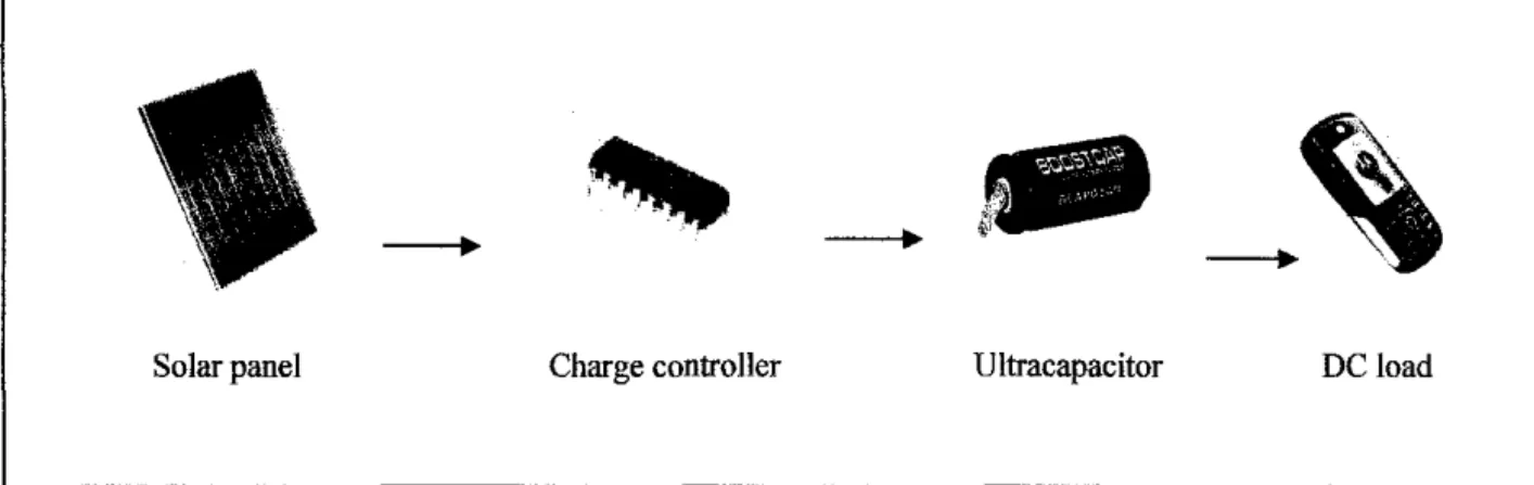
-- --
Solar panel Charge controller Ultracapacitor DC load
Figure 5: Overall design system
3.4 Solar Energy
At this stage, the main objective is to determine the solar cell configuration in term of size, capacity and efficiency. The main issue of solar energy is that it depends on the weather. Because of that, problem such as voltage drop and fluctuating voltage from solar energy must be taken into account when designing the charging circuit.
3.4.1 Research on PV cell
It is important to do research on PV in order to get better understanding of the system. The research will be covered on types of PV, the characteristics, the problems associated with it, the price and others.
3.4.2 PV cell size
Since the project focuses on making the prototype portable, the size of the PV is a major aspect in selecting the PV. After some research on the PV cell, the size of the PV cell will be determined based on its application. For the project, preferable size of PV cell would be the average size of pencil box.
When the sunlight falls on the cell area, the amount of energy that falls direct on the area is proportional to that area. The energy of full sunlight in Malaysia is approximately 1000 watts per square meter. Energy on the cell can be calculated by multiplying the constant with the area of the cell. For this project, it is assumed that full sunlight is coming straight on the cell. If the sun comes in at an angle, there is an additional constant of the cosine of the angle that must be multiplied in and other complications, such as optical effects that change the efficiency at different angles. [1 OJ
Energy out = width
*
height*
1000 watts/m2*
cell efficiency3.4.3 Testing
After the size and the rating for the PV is decided, a set of testing will be designed to get the data of the PV cell. The testing will be done using simple circuit during bright day. The main objective is to know the capability of the PV cell and how much voltage and current the PV can produce. The voltage from PV cell will be measured and recorded.
3.5 Energy Storage Unit (Ultracapacitor)
In this part, the focus will be more on designing the charging circuit for the prototype. During the early stage, a couple of circuit will be designed and tested for its function and suitability of the project. The testing will be done in PSpice simulation and the actual circuit analysis in the laboratory. The most suitable circuit will be chosen for the prototype. Other than testing the function of the circuit, other factors such as availability of the component also will be taken into account.
Early stage of the process shown that most of the electronic components in the circuits are easily found in the lab or electronics shop except for ultracapacitor. Since ultracpacitor is a new electronic components, it is hard to find one. The strategy is to find local distributor and order from them.
3.5.1 Design Process
The objective of the project is to design a prototype of power source that use ultracapacitor as energy storage component. As mention in the literature review part, ultracapacitor is still a new technology and still not widely use in the market. A comprehensive review on the ultracapacitor is essential in order to get a clear picture on its characteristic, function and behaviour. For example, an RC circuit will be very useful for the charging circuit since ultracapacitor have quick discharge rate compared to battery. Other than focusing on ultracapacitor, the designing process also involved in investigating and evaluating conventional way of storing energy which is battery. Comparison will be made and discuss later in the next chapter.
3.5.2 Testing
After the charging circuit is ready, a series of testing will be done in variety of condition and configuration. The test also included series and parallel connection of ultracapacitor and battery. Other factors such as weather also will be taken into account. Basically, the testing will be done using Pasco, Data Logger. By connecting the device to the computer, it can record and plot the voltage or current versus time graph. All the results will be discuss in detail in result and discussion part.
4.1 Results
CHAPTER4
RESULTS AND DISCUSSIONS
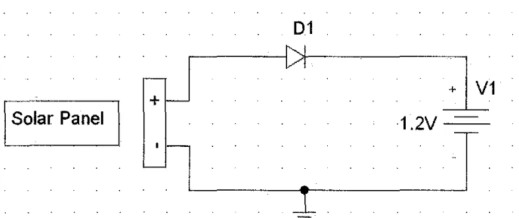
.J. 1.1 Photovoltaic Cell
For the chosen solar panel in Figure 6, an experiment was done to test the capability of the device. Figure 7 shows the circuit that is used for the experiment. The results of the experiment are shown in Table 2. Based on the table, the maximum voltage produce from the solar panel is 7.11 and the minimum voltage generated is 5.28V at 4.48 pm.
Figure 8 shows the voltage spike from the solar panel. The figure clearly shows that voltage produced is varying with the weather conditions. As mentioned in the literature review part, this kind of voltage could potentially damaged or reduce the life cycle of batteries. Ultracapacitor on the other hand will not be affected by the unstable voltage since it is designed to be more robust compared to battery. Overall, the experiment shows that the solar panel that will be used for the prototype is capable of producing enough voltage to switch on the MAX712 and at the same time charge the 4.6V ultracapacitor ..
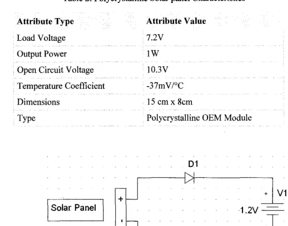
Table 2: Polycrystalline Solar panel Characteristics Attribute Type
Load Voltage Output Power
. Open Circuit Voltage . Temperature Coefficient
Dimensions Type
Solar Panel
Attribute Value 7.2V
lW 10.3V -37mV/°C
15 em x 8cm
Polycrystalline OEM Module
01
1.2V
~
-+ V1
T
Figure 7: Simple Charging Circuit to test the Solar Panel Output
Table 3: Experiment Result
Time Solar Patlfll Output Voltage Sob!r Pli.nelQutput CWTent
11.27 a.m 7.11
v
102mA12.54p.m 6.52
v
IOOmA.
2.06p.m 6.27V 95.4 rnA
3.03 p.m 6.32
v
95.3 rnA4.03 p.m 5.86
v
70.1 rnA4.48 p.m 5.28
v
52.1 rnA5.23
5.21
S.1~ ·
- 5,11
Figure 8: Voltage spike from PV 4.1.2 Ultracapacitor
After testing the solar panel, the next step is to test the ultracapacitor capability of charging and discharging voltage. The experiment was done by charging ultracapacitor using a constant SV power supply. The main objective of the experiment is to determine the characteristics of ultracapacitor when it is charging and discharging. For this experiment, two ultracapacitors of SOF and 2.3V each are installed in series to get a total of 4.6V. In theory, the potential difference between S.OV and 4.6V will ensure the ultracapacitor is in charging mode. The results are as shown in the Figures 9, I 0 and 11.
Figure 9 shows the voltage of ultracapacitor when it is charging. From almost 0 voltage, the ultracapacitor only takes about 40 minutes to reach 4V.
When it reaches 4V the charging rate becomes slower. As the voltage increases and reaches the maximum charging voltage (4.6V), the current decrease towards OA. The next step is to investigate whether the ultracapacitor is capable of storing energy when it is fully charged.
As soon as the ultracapacitor is fully charged, the SV power source is taken off and the ultracapacitor is left alone in the circuit without any load attached to it. Figure 11 shows the ultracapacitor voltage when it is in discharging mode. After 12 hours, the ultracapacitor voltage shows a reduction of only 0.2V.
f ... ___ ~
..=...·- """"" ...
iii s...,. - Sotup I ~SOon I & c~-'"~~~L
Ooto • ---~-~~!il(i£J_!j F~• • 0 ... • X
'"'-";: Vollo.o.CWI[
-.&f!..,.., e\ r co ... no,cnat
Ill~ •• ..,
• 0' '"'OJ""•
-lo.fF1 ooVGnoph
k:G...,h1 Jlo.Hostoo"""
0Mo!eo 'J...Scooo
<!'\"S"""'"""""
, ~S""ndC'""''
= 11!1 Tab1o , m!Toblo1
'IDW•"'"''"
v .
. .Figure 9: Graph ofultracapacitor voltage charged with constant SV power source vs time
Figure 10: Graph ofultracapacitor current charged with constant SVpower source vs time
For the charge controller circuit, the design is as indicated in Figure 12.
MAXIM (MAX712) fast-charge controllers will be used in the circuit. The key features for the IC are listed in the Appendix A.
r- ..
C4
+ R5
~
68kQl Solar Panel 1 C6
IOU Rl
~1Dk
d , DIIJ';-IQ.JI
O.Oiu
I . 'L·~22k~---_j
Figure 12: Charge Controller circuit
a) MAXIM (MAX712) fast-charge controllers
The MAX712 fast-charge controllers are used to charge from a DC source at least 1.5V higher than the maximwn storage component. One of the features of the integrated circuit (IC) is a voltage-slope detecting analog-to- digital converter, timer, and temperature window comparator that determines charge completion. The MAX712 are powered by the DC source via an on- board +5V shunt regulator. The IC draws a maximwn of 5JlA from the storage component when it is not charging. A low-side current-sense resistor allows storage being charged and at the same time still supplying power to the batteries load. The MAX712 terminates fast charge by detecting zero voltage slopes.
b) Circuit Testing
Basically, the experiment is divided into 2 parts. The first one will be the circuit that tests the usage of ultracapacitor without battery and the second circuit is using battery and ultracapacitor in parallel. The main objective of the experiment is to determine either circuit constructed are working.
Figure 13: Experiment using SV adapter to replace Solar Panel
Figure 14: Experiment to power up SV Server Motor
Figure 15: Experiment to power up 3.5V light bulb
After series of testing and adjustment, the circuit finally is functioning as desired. The first experiment shown in Figure 13 is done by using 5V adapter to power up the circuit. ln this experiment, voltage regulator (KA 7805), is used to ensure constant 5V were delivered from the electrical plug to the circuit. The ultracapacitor used in this experiment (5F) only takes almost 5 minutes to fully charge. Since the value of the capacitance used is small, the energy stored in the ultracapacitor only lasted for 2 minutes maximum. In the second experiment, the circuit is powered up using a new solar panel.
Both experiments show that the circuits are functioning as they should be. The next step after this is to do more testing on the prototype.
4.1.4 Prototype
a) Experiment Setup
For the prototype experiment, it is carried out on a cloudy day. The experiment is done in such a manner to get the minimum value of voltage produced from the PV and observed if it is enough to charge the ultracapacitor.
Figure 16 shows the setup of the experiment. The circuit is installed in a box to protect it from the heat from the sun. Both solar panels were installed at the top of the box. The experiment is carried out for almost full day, from 7 am until 7 pm. The highest voltage recorded is 5.2V and the minimum is 4.2V. The graph of voltage versus time for the experiment is shown in Figure 17.
Figure 18 shows the graph of voltage before and after the MAX712. The graph clearly shows that MAX712 is able to reduce the voltage spike from the solar panel. During the experiment, the reading from ultracapacitor is also monitored and data recorded. Figure 19 shows the graph of ultracapacitor voltage versus time.
b) Results:
Figure 16: Experiment Setup
t.~,,. ,. , •r h 1 • ' _ -<!'! ~
,
. ..
• •"
-j
f
llll,ll
- . I
..
-
~.
Tlmo(o)
,...,. 15000 20CIOO 30000
Figure 17: Graph of voltage from solar panel vs time
~ <,, .• ., .. • I - II n II"$CJ
I• Run"'2
1 0
_,...____
~--...--
4 0 + 1- "'t.Jn •.t
3.5
..
3 0
2.5
2 0 nme( s )
50 100 150 200 250 300 350
Figure 18: Graph of voltage from solar panel before and after MAX712 vs time
~"· ·J.. C·!
20
1 •
••
..
10000 TOme(•) JOOOO ,..,..
>0000 .15th)OFigure 19: Graph of ultracapacitor voltage vs time
4.2 Discussions
4. 2.1 Energy Storage Unit (ESU)
Energy storage unit is the main focus for this project. Storage medium is used to store energy generated by solar panel and to ensure the energy or power produced can be used for the load. Typical solar power source systems use battery as its storage medium. However, energy storage in battery is limited to alkaline or rechargeable batteries.
In addition, these rechargeable batteries also are related to the problem of efficiency, availability and lifetime [15].
The problem with the efficiency, availability and lifetime of battery has moved people attention to another technology such as ultracapacitor. Ultracapacitors have found their way into many design engineers' product development strategies for portable devices. These strategies include using batteries and ultracapacitors in parallel or complete battery replacement with ultracapacitors. In both strategies, the main objective is to use ultracapacitor as energy storage. Based on the experiment done, it is proven that ultracapacitor is definitely capable of storing energy for future usage. However, to know how long the energy could last, a calculation can be made using the basic formula.
Rearrange For 500F, 12V
Convert to mAh
q=CV q = 500* 12
=6000
l q = 0.2777777778mAh 6000q = 1666 mAh
C Capacitance V Voltage
Q~coulomb
From the calculation, it can be conclude that ultracapacitor with 500F and 12V can provide power up until two hours for the load that required around 800mAh.
Compared to battery, ultracapacitors contain no heavy metals and do not have the environmental concerns as some battery chemistries have. Another advantage of using ultracapacitor is the lightweight characteristic that it possesses. A single D-cell ultracapacitor at 2.5 V weighs approximately 60 g, whereas a D-size battery is significantly heavier and depends on the chemical elements. In addition, for alkaline cells, the voltage is only 1.5 V, requiring additional weight for equivalent voltage.
In ultracapacitors, the electrode is based on a carbon technology that allows for a very large surface area. The combination of this surface area along with a very small charge separation gives the ultracapacitors the high energy densities they possess. Most ultracapacitors are rated in farads and typically can be found in the 1 to 5,000-F range and rated in the 2.5 to 2.7- V ranges [12].
Ultracapacitors also can be charged and discharged at extremely high rates compared to batteries. Conventional rechargeable batteries can take several hours to recharge. Newer "rapid-charging" batteries still require several minutes to an hour to be fully charged. An ultracapacitor can be recharged within a matter of seconds or minutes depending on the amount of current available for recharge [16].
Table 4: Energy Storage Characteristics
Characteristics Ultracapacitor Battery (Lithium ion)
Charging/Discharging Quick Slow
Duration
Charge Cycle 100000 1000
Temperature -40°C -75°C 0°C-45°C
Operating Cost No cost Costly
Maintenance No maintenance for over Regular battery 10 years charges every 2-3
years
Equivalent Series Resistant Low High
Disposable Part No Yes
From Table 4, ultracapacitor is better than lithium ion battery in term of charge cycle, temperature, operating cost. maintenance, disposable part, and explosive. Below is the example of ultracapacitor that will be using in this project.
10 Farad 40 Farad 1 Farad
Figure 20: The three different ratings of ultracapacitors
4.2.2 Loads
In order to design a power source, the capacity of the load or power consumption of the electrical loads must be known to ensure the reliability of power supply. Since the target group for the project is army and traveller equipment, the power consumption of the load can be considered as low voltage application. Table 5 below shows the list and rating of some of the equipment.
Table 5: List of the target loads for the power supply
Equipment Volt Current T~
Walkie talkie Two-Way Radio 7.2 400mA DC
Nokia 6300 5.0 350mA DC · -
Sony Ericsson K550 4.9 450mA DC
CHAPTERS
CONCLUSION AND RECOMMENDATIONS
5.1 Conclusion
For this context of project, a prototype of a DC portable solar-powered electrical device using ultracapacitor as energy storage unit has been theoretically examined and experimentally validated. Currently, the power requirements of a nwnber of applications have dramatically increased and some case have exceeded the capability of batteries of standard design. Therefore it is necessary to use other alternative strategies.
Ultracapacitor has many advantages compared to battery despite the price of ultracapacitor that is still quite expensive due to their early stages of development and low production volwnes.
5.2 Recommendations
The prototype proposed still can be improved in many ways. The modifications and improvements are:
• For high voltage and continuous power supply application, a higher value of ultracapacitor can be used.
• A device or method can be developed to reduce the discharging rate of the ultracapacitor.
• The design of the charger circuit can also be improved to better suit the usage of ultracapacitor.
• The result of the testing can be further improved by showing the rapid charging characteristic of the ultracapacitor.
REFERENCES
[1] Wan Anis Masila binti Wan Abdullah Sani "Lightweight Power Supply" Final Year Project, Universiti Teknologi PETRONAS. 2008
[2] Mark Warner, .. Military Batteries Face Unique Challenges" (2002) http://www.ultralifebatteries.com/engineers.php?ID= 13
Retrieved on 20th September 2008
[3] Ahmad Hadri haris, Wan Faizal Anwar, TNB Research Sdn. Bhd, Experience in Conducting Research On Pilot Grid Connected Solar Photovoltaic Systems in Malaysia. 2002
[4] Prof Dr Mohd YusofOthman, Dr Kamaruzzaman Sopian, Dr Baharudin Yatim, Renewable Energy Sources in Malaysia, Seminar on New & Renewable Energy Development & Utilization for Global Environment Protection (2001)
[5) Che Wan Hasnawati Aiza binti Che Wan Ahmad "Design of a Solar Photovoltaic AC/DC Supply System" Final Year Project, Universiti Teknologi PETRONAS. 2005
[6] U.S Department of Energy. Energy Efficiency and Renewable Energy http://www1.eere.energy.gov/solar/solar cell materials.html
Retrieved on 3rd October 2008
[7] U.S Department ofEnergy. Energy Efficiency and Renewable Energy http://www l.eere.energy.gov/solar/photovoltaics.html
Retrieved on 3rd October 2008 [8] http://whatis.techtarget.com/
Retrieved on 11th of September 2008
[9] Howard T. Francis. "Space Batteries" National Aeronautics and Space Administration 1964.
http:/ /www.grc.nasa.gov/WWW /Electrochemistry{ Retrieved on 11th of September 2008
[1 0] Luqman bin Radzuan " Hybris Charger for Mobile Home" Final Year Project, Universiti Teknologi PETRONAS. 2008
[11] Tongzhen Wei *, Xinchun Qi, Zhiping Qi "An Improved Ultracapacitor Equivalent Circuit Model for the Design of Energy Storage Power Systems"
Institute of Electrical Engineering, Chinese Academy of Sciences, China.
October 2007
[12] Bobby Maher "Selecting an ultracapacitor" Maxwell Technologies San Diego, CA
http:/ /www.maxwell.com Retrieved on 5th August 2008
[13] R. Ko .. tz a,*, M. Carlen. "Principles and applications of electrochemical capacitors" Paul Scherrer Institut, General Energy Research Department, CH- 5232 Villigen, Switzerland b ABB Corporate Research, CH-5405
Baden:Da··ttwil, Switzerland, December 1999
[14] G.L Bullard, H.B. Siera-Alcazar, H.L Lee, J.L. Morris. "Operating Principles of the Ultracapacitor." Pinnacle Research Institute, Inc. January 1989.
[15] A. Andreotti*, F. Mottola, M. Pagano, G. Velotto "Design ofultracapacitor based filter for isolated PV source feeding pulsing load" Electric Power System Research. 2007
[16] John Dispennette, "Ultracapacitors Bring Portability to Power" Application Engineer, Maxwell Technologies, San Diego, Calif.
APPENDICES
APPENDIX A
DATASHEET FOR MAXIM 712
19·0100; Rev 3. 1197
• Ill
_ _ _ _ _ _ General Description
The MAX712/MAX713 fast charge Nickel Metal Hydride (NiMH) and Nickel Cadmium (NiCd) batteries from a DC source at least 1.5V higher than the maximum battery voltage. 1 to 16 series cells can be charged at rates up to 4C. A voltage-slope detecting analog-to-digital convert- er, timer. and temperature window comparator determine charge completion. The MAX712/MAX713 are powered by the DC source via an on-board +SV shunt regulator.
They draw a maximum of SjA from the battery when not charging. A low-side current-sense resistor allows the battery charge current to be regulated while still supplying power to the battery's load.
The MAX712 terminates fast charge by detecting zero voltage slope. while the MAX713 uses a negative voltage-slope detection scheme. Both parts come in 16- pin DIP and SO packages. An external power PNP tran- sistor, blocking diode, three resistors. and three capacitors are the only required external components.
For high-power charging requirements, the MAX712/
MAX713 can be configured as a switch-mode battery charger that minimizes power dissipation. Two evaluation kits are available: Order the MAX712EVKIT-DIP for quick evaluation of the linear charger, and the MAX713EVKIT- SO to evaluate the switch-mode charger
---·~fications
Battery-Powered Equipment
Laptop, Notebook. and Palmtop Computers Handy-Terminals
Cellular Phones
Portable Consumer Products Portable Stereos
Cordless Phones
_ _ _ _ _ _ _ Pin ConfifiUJ'ation
TOP VIEW
DIP/SO
.NI~XINI
NiCdJNiMH Battery Fast-Charge Controllers
_____________
Faa~+
Fast Charge NIMH or NICd Batteries+ Voltage Slope, Temperature, and Timer Fast-Charge Cutoff
+ Charge 1 to 16 Series Cells
+
Supply Battery's Load while Charging (Unear Mode)+
Fast Charge from C/4 to 4C Rate+
C/16 Trickle-Charge Rate+ Automatically Switch from Fast to Trickle Charge
+
Linear or Switch-Mode Power Control+
StJA Max Drain on Battery when Not Charging+
5V Shunt Regulator Powers External Logic_ _ _ _ _ _ Ordering Information
PART TEMP. RANGE PIN ..PACKAGE MAX712CPE o·c to+ 1o·c 16 Plastic DIP MAX712CSE o·c to +70"C 16 Narrow SO MAX712C/D o·c to ·~ 1o·c Dice·
MAX712EPE -40"C to +85"C 16 Plastic DIP MAX712ESE -40"C to +85"C 16 Narrow SO MAX712M.JE -ss·c to + 12s·c 16 CERDIP'' Ordering lnforrlvtlon continued at end of datJI shHt
·Contact factory for dice specifications.
··contact factory for availabiliry and processing to MIL-STD-883.
DC IN
l~F +
l)pical Operating Circuit
OR\/
VLIMIT BATT+
t---•
01 1~001
~F .-~-,
MAXIAII C3
MAX712 BATTERV + + 10¢
MAX71J
SEE FIGURE 19 FOR SWITCH-MOD£ CHARGER CIRCUIT.
~~)(I~ ____________________________________________ Mulmm~m~~uas 1
NiCdAViMH Battery
Fast-Charge Controllers
ABSOLUTE MAXIMUM RATINGS
v ... to BAIT-..... ... ·0.3V. + 7V BATT-toGND ... tlV BAIT• toBAIT-
Power Not Applied ... t20V With Power Applied. .. . .. . . . . .. The higher or ±20V or t 2V x (programmed cells) DRV to GND. ... .. ... .. . .. ... .. . . -0 3V, t20V
FASTCHG to BAIT-... . ... -0.3V, + 12V All Other Pins to GND ... A>.3V. (V+ + 0.3V) V+ Current... . ... lOOmA DRV Current. .. .. .. .. .. .. .. .. . ... . ... 1 OOmA
REF Current. .. . . . lOrnA
Continuous Power Dissipation (T A • + 70"C)
Plastic DIP (derate 10.53mwrc above •70"C ... 842mW Narrow SO (derate 8.70mW/"C above t 70"C ... 696mW CERDIP (derate lO.oomwrc above + 70"C ... aoomw Operating Temperature Ranges
MAX7l_C_E ... o·c to +70"C MAX7l_E_E ... -40"C to +85"C MAX7l_MJE.. . .. ... .. . .... -55"C to+ 125"C Storage Tem~ature Range ... -65·c to+ 150"C Lead Temperature (soldering, 105ec) ... +300'C
Stresses beyond those l1sted under 'Absolute M;mmum Ratings· may cause permanent darTiiJge to the deVICe. These are suess raungs only. and functlOnal operation o1 the devrce at these or any other condltl0/1!> beyond /ho<;e 1ndrcated tn the operat,onal secll0/15 olthe specificatiOns IS not 1mplled Exposure to absolute max1mum rat1ng condltlon!i for extended periOds may affect dcvrce rel1abi/Jty
ELECTRICAL CHARACTERISTICS
(lv. • lOrnA. TA TMtN to TMAx. unless otherwr;>e noted. Refer to Typical Operating Circuit. All measurements are with respect to BAIT·, not GND.)
PARAMETER CONDITIONS MIN TYP MAX UNITS
V+ Voltage 5mA < lv. < 20mA 4.5 5.5 v
lv. (Note 1) 5 mA
BAIT+ Leakage V+ .. OV. BAIT+ u 17V 5 IJA
BAIT+ Resistance with Power On PGMO • PGM1 =BATT-. BAIT+- 30V 30 kn
C1 Capacttance 0.5 ~F
C2 Capacttance 5 nF
REF Voltage 0mA < IREF < 1mA 1.96 2.04 v
Undervoltage Lockout Percell 0.35 050 v
External VLIMIT Input Range 1.25 2.50 v
THI. TLO, TEMP Input Range 0 2 v
THI. TLO Offset Voltage (Note 2) OV < TEMP < 2V, TEMP voltage ristng -10 10 mV
THI. TLO, TEMP. VLIMIT Input Bias Current -1 1 IJA
VLIMIT Accuracy 1.2V < VUMIT < 2.5V, 5mA < IORV < 20mA.
-30 30 mV
PGMO .. PGM1 • V+
Internal Cell Voltage Limit VUMIT • V+ 1.6 1.65 1.7 v
Fast-Charge VSENSE 225 250 275 mv
PGM3 • V+ 1.5 3.9 7.0
Trickle-Charge VSENSE PGM3 • open 4.5 7.8 12.0
PGM3 • REF mV
12.0 15.6 20.0
PGM3 • BAIT- 260 31 3 380
Voltage-Slope SenSitivity (Note 3) MAX713 -2 5 mVItA
MAX712 0 per cell
Timer Accuracy -15 15 %
Battery-Voltage to Cell-Voltage
-1 5 1.5 %
Divider Accuracy
DRV Sink Current VORV • 10V 30 mA
NiCdJNiMH Battery Fast-Charge Controllers
ELECTRICAL CHARACTERISTICS (continued)
(lv+ • 10mA. TA TMIN to TMAX. unless otherwise noted. Refer to Typical Operating Clfcuil All measurements are with respect to BATI-, not GND.)
PARAMETER CONDITIONS MIN TYP MAX UNITS
~ASTCHG Low Current V~ASTCRG • 0.4V 2 mA
FASTCHG High Current VFASfcRG• 10V 10 IJA
AID Input Range (Note 4) Battery voltage ~ number of cells programmed 1.4 1.9 v
' - -
Note 1: The MAX7121MAX713 are powered from the V+ pm. Since V+ shunt regulates to +SV, R1 must be small enough to allow at least SmA of current 1nto the V + pin
Note 2: Offset voltage of THI and TLO comparators referred to TEMP.
Nota 3: lA is the AID sampling interval (Table 3).
Note 4: This specification can be violated when attempting to charge more or fewer cells than the number programmed To ensure proper voltage· slope fast-charge termination. the (maximum battery voltage) + (number of cells programmed) must fall within the AID input range
_ _ _ _ _ _ _ _ _ _ _ _ _ _ _ Typic.l Operating Cllaracrerisrics
(T A .... 25 ·c. unless otherwise noted )
20
10
0
-10
-20
100
~
01
1k
CIIIRDITo$EIISE ...0 FII£QUEIICY ~ (lltlh15pf)
~~~~·.,w'll FAST,•C'N
10k lOOk 1M 10M
FREQUENCY (Hz)
~ 5.8
SIUIJ-11£-.AlOit VOLTAGl n. CIIIRDIT
20
10
0
-10
·20
FASTCHG • C'N, V+ • SV
I
56 1-DRVINOT SI~ING ~R~ ~54
~ 52 w
C) so
<
,_
...J
g u
> + 46 u
i j
. / t/"
~
~
SIMIING CURRENT-/ /""'
1/'
If 1\'\ 4.2
1.95 1.97 199 2.01 2.03 2.05 40 0
![Figure l: A typical solar cell system [ 6]](https://thumb-ap.123doks.com/thumbv2/azpdforg/11143808.0/11.848.322.595.776.939/figure-l-a-typical-solar-cell-system-6.webp)
![Figure 2: Basic Voltage Regulator Block Diagram [ 5]](https://thumb-ap.123doks.com/thumbv2/azpdforg/11143808.0/15.851.132.804.679.1009/figure-2-basic-voltage-regulator-block-diagram-5.webp)