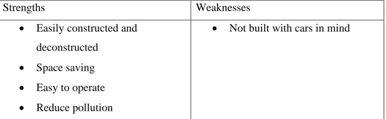
The system will use Geany as programming software and Python as programming language. The system can retrieve data from the file, get input from the user, compare data, store data, and control the other components. The whole structure will be wooden, use about 5 motors and RPi to control it.
The challenges this project will face will be the cost, tm and work that will have to be put in to actually implement in the real world.
Introduction
- Problem Statement and Motivation
- Project Scope and Direction
- Project Objectives
- Contributions
- Background information
- Project Timeline
- Report Organization
The user can easily use the system and be assured of the safety it offers. To use the system, the user parks his car in the designated spot and enters the interface to set a password. The lock number and password are stored in the system and the mechanical components then start and move the parked car to the designated spot underground.
On top of that, anyone with a user-friendly interface will be able to use the system.
Literature Reviews
Car Parking Problem in Urban Areas, Causes and Solutions
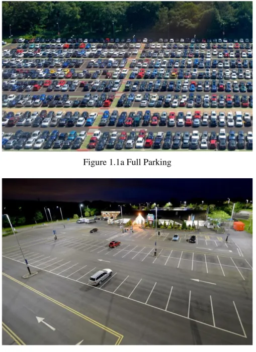
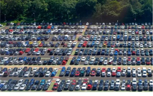
Dark parking lot pavements were said to promote water quality degradation, increase air temperature and consume soil. Parking lots are also considered the most environmentally damaging type of land use. The main objective was to discourage people from driving as they would have to pay a fee just to park.
Even if it worked, there would still be a huge area used for parking, and as mentioned before, car parks are considered the least glamorous and most environmentally damaging form of land use.
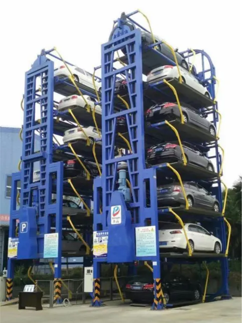
Previous Inventions
- Parkmatic Automated Carousel
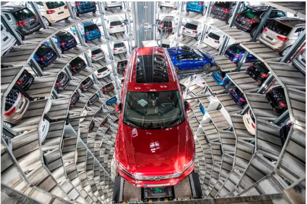
- Volkswagen’s Car Towers at Autostadt in Wolfsburg, Germany
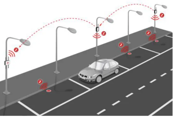
- IoT based Smart Parking System
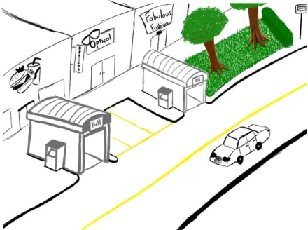
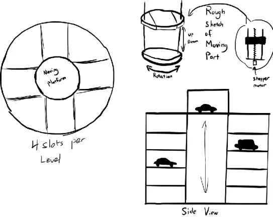
The space outside the outer circle will be considered the free space where it is not part of the building and can be used to build other things. The space between the outer circle and the inner circle would be used to house the cars, as intended. The data will be updated to the cloud, which stores the records related to the parking area.
By reducing the area used by expanding underground, we would be able to utilize the minimal space and hold the maximum number of cars.
PROPOSED METHODOLOGY/APPROACH
System Design Diagram
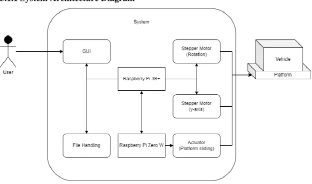
- System Architecture Diagram
- Use Case Diagram and Description
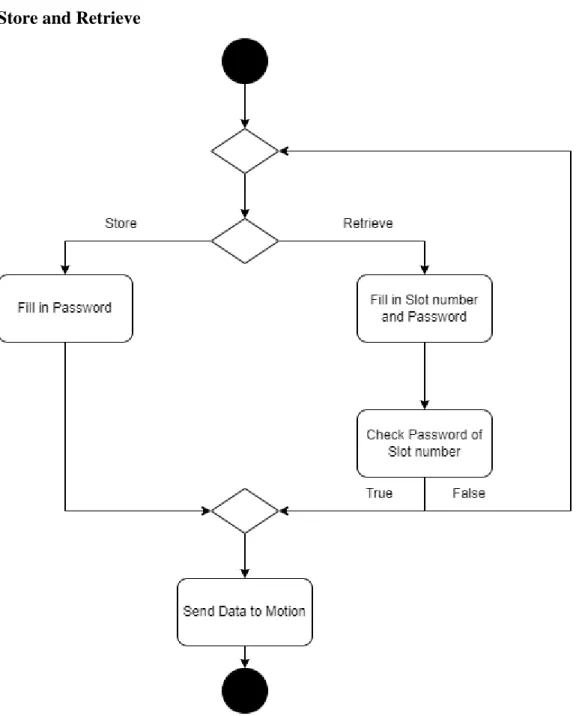
- Activity Diagram Store and Retrieve
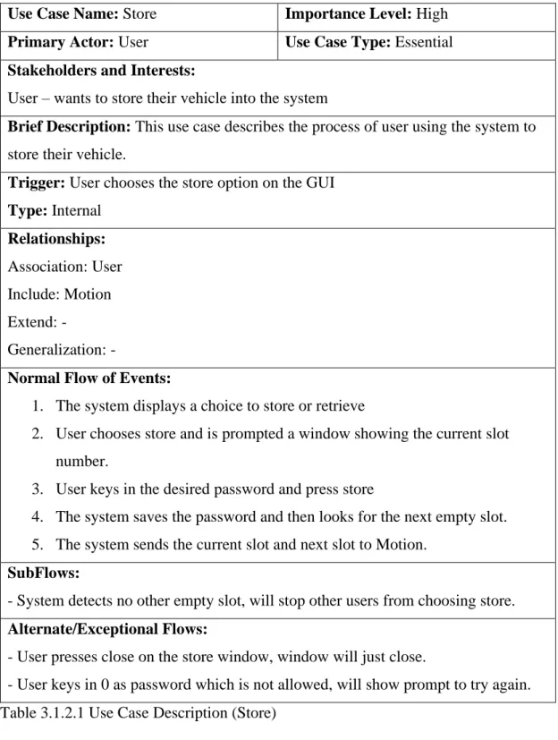
Brief description: This use case describes the process of user using the system to store their vehicle. User keys in 0 as password not allowed will show retry message. Brief description: This use case describes the process of user using the system to recover their vehicle.
The user decides to acquire and a window appears in which he must enter the slot number and password. The system checks the corresponding slot number and checks the stored password and the one entered by the user. Brief description: This use case describes the process of moving the system after obtaining the required data.
Trigger: The system retrieves the current slot number and the next slot number. Type: internal and external. The system will calculate the angle and level of the current slot and the next slot.
System Design
- System Overview
- General Work Procedures
- Tools
- Hardware in Use
- Software in Use
- Programming Language in Use
- Circuits and Tools Design
- Flowchart
With a fixed pilot screw that will rotate, as long as there is another support point for the platform connected to the pilot screw, the platform will be able to slide along when the pilot screw rotates. There is a possibility to make it completely wireless as well by fitting a power cell which will be charged when the system is idle. Since the small base will be moving most of the time, the idea to keep it as light as possible is to not add additional stress to the base motors, so we want to reduce wiring and size of the components.
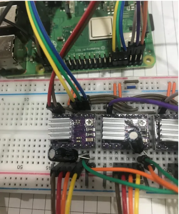
So we chose the RPi 3 B+ as the main base RPi and the RPi Zero W as the small base RPi. All the movements of the system will be done with these motors, because we want to have accurate numbers about the angle, the height and when the system moves the platform to the right places, this is all to ensure that the vehicle does not get damaged or fall while going from slot to slot . The coils of the motors should be determined so that one coil will be on A1, A2 and the other on B1, B2.
This part of the system is built on top of the moving platform, so the lighter the components, the better. The connections of this part of the system are almost the same as those with the DRV8825 stepper motor driver, but since we will be using a linear actuator, we will use L298N as the motor driver. The Ena will be used to check that the linear actuator is getting power, so if it is low there will be no movement.
The communication between the two Rpi's, Raspberry Pi 3 B+ and Raspberry Pi Zero W, will be done using MQTT. So when the system starts up, all this data will be read into the system and after each set of moves, the data will be updated from the system to the file.
System Implementation
Hardware Setup
- Raspberry Pi 3 B+ to DRV8825 drivers
- Stepper Motor/Lead Screw
- Raspberry Pi Zero W to L298N to Actuator
- Raspberry Pi 3B+
- File Handling and LED
- Hardware Declaration (DRV8825)
- Movement
- MQTT
- Raspberry Pi Zero W
- Hardware Declaration (L298N)
- MQTT and Movement
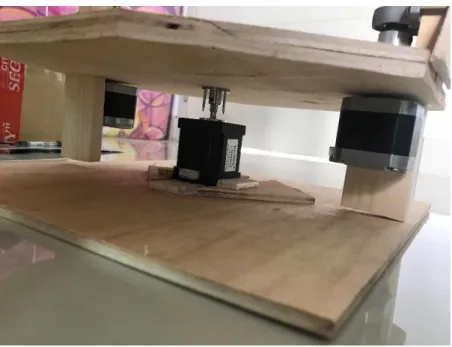
Two of the stepper motors will be connected to lead screws using a flexible coupling shaft. On each of the pilot screws will be a screw nut which will then be used to mount the moving platform. The only thing that needed to be added was the calculations that will be made to order the motors, formulas were used to set 5 levels with 4 corners on each level, representing 4 slots on each level.
The codes are briefly explained below with the provided code snippets of the actual code. We then retrieve the data from parkingslot.txt and check whether all slots are filled. Next, we define a function that will run to store the data in the file and check if the slots are full.
With the previous statement, we will use it to define a base move function which will be used by all other move functions. As we can see, the move function will be called when the user wants to store or pick up their vehicle, this is where the calculations are done. We will also take the input action, to know what to do with the current slot.
Since RPi 3B+ will communicate with RPi Zero W via MQTT, this will be the code. As we can see from the code above, there will be different messages published and received as there will be communication between the two RPs through all the movement movements.
Final Assembly
Since the motors are up in the air, if the two wooden planks are not there, instead of turning the lead screw, the motors will be the one turning. So to solve this, two wooden planks placed next to the motors that control the y-axis to stop the motors from turning. Between the two motors for the y-axis is the motor for the rotation, which also carries the entire weight of the model.
There would be better ways to accomplish this task, providing a larger and more stable base, however it was the only way I could think of at the time. For this part of the system, it shows the upper part, with the moving platform below it. From the image, a simulation of the platform being slid in or out is shown.
To do this, as explained in Chapter 4, a hole is cut into the movable platform, and a position is also made to attach the platform with the actuator.
Implementation Issues and Challenges
System Evaluation and Discussion
System Testing and Performance Metrics
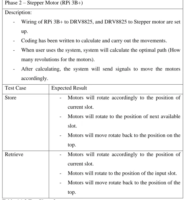
For example, when the current slot is 01 and the user wants to retrieve slot 05, the y-axis motors will rotate 5 revolutions counter-clockwise to get to slot 01. The rotation motor will rotate 90 degrees clockwise, followed by another 5 revolutions counter-clockwise with y-axis motors to get to slot 05. And finally, the rotary motor will rotate 90 degrees counter-clockwise, followed by 10 clockwise rotations of the y-axis motor to get back to the top.
Several of these tests will be run to test out several different slots. Run the file - RPi 3B+ publishes a message to RPi Zero - After RPi Zero receives message, RPi Zero gives a reply. For this phase of the test, it can be performed before everything is placed in the model and also after the final prototype is assembled.
Test Setup and Results
Objective Evaluation
Conclusion
Recommendation
Faculty of Information and Communication Technology (Kampus Kampus), UTAR. Trading) Ltd, “Buy Raspberry Pi 3 Model B+”, Raspberry Pi.
APPENDIX
FINAL YEAR PROJECT WEEKLY REPORT
WORK DONE
WORK TO BE DONE
PROBLEMS ENCOUNTERED
SELF EVALUATION OF THE PROGRESS
TEOH
Reworked some of the coding on RPi 3B+ as some bugs were found two weeks before. Will pick up the pass once back at campus as there is a power supply to not test cars out. Had to do some research on other tools to use instead of stepper motors.
Since the testing of L298N with stepper motor was met with failure, it is caused by lack of knowledge and understanding. Might try to solve this by doing more research, but after thinking about it, decided that maybe the stepper motor is not a good choice for the moving platform. Tested RPis communication and reworked parts of the code Continued work on the wooden model.
As mentioned, there were some issues with MQTT combined with all the motion features. Most of them were solved with some research, but some were temporary solutions.
PLAGIARISM CHECK RESULT
Parameters of originality required, and limits approved by UTAR are as follows:. i) Overall similarity index is 20% and below, and. ii) Matches of individual sources listed must be less than 3% each, and (iii) Matching texts in continuous block must not exceed 8 words. Note: Parameters (i) – (ii) will exclude citations, bibliography and text matches that are less than 8 words. Note: Supervisor/candidate(s) are expected to provide a soft copy of the complete set of originality report to the Faculty/Institute.
Based on the above results, I declare that I am satisfied with the authenticity of the Final Year Project Report submitted by my student(s) as mentioned above. Form title: Supervisor's Comments on Originality Report Generated by Turnitin for submission of Final Year Project Report (for Undergraduate Programs).
UNIVERSITI TUNKU ABDUL RAHMAN FACULTY OF INFORMATION & COMMUNICATION
TECHNOLOGY (KAMPAR CAMPUS)