Intelligent Design of Microneedle Structure for Drug Delivery System
by
Nur Afifah Binti Ismail (1130110665)
A thesis submitted in fulfillment of the requirements for the degree of Master of Science (Microelectronic Engineering)
School of Microelectronic Engineering UNIVERSITI MALAYSIA PERLIS
2015
© Thi
s i tem
is pr ot ec ted by
or igi nal
c opy
right
i
DECLARATION OF THESIS
Author’s full name : NUR AFIFAH BINTI ISMAIL Date of birth : 15 MARCH 1988
Title : INTELLIGENT DESIGN OF MICRONEEDLE STRUCTURE FOR DRUG DELIVERY SYSTEM
Academic Session : 2012 - 2015
I hereby declare that the thesis becomes the property of Universiti Malaysia Perlis (UniMAP) and to be placed at the library of UniMAP. This thesis is classified as:
CONFIDENTIAL (Contains confidential information under the Official Secret Act 1972)*
RESTRICTED (Contains restricted information as specified by the organization where research was done)*
OPEN ACCESS I agree that my thesis is to be made immediately available as hard copy or on-line open access (full text) I, the author, give permission to the UniMAP to reproduce this thesis in whole or in part for the purpose of research or academic exchange only (except during a period of _____ years, if so requested above).
Certified by:
___________________________ __________________________
SIGNATURE SIGNATURE OF SUPERVISOR (880315-35-5016) DR. NURUL IZZA MOHD NOR (NEW IC NO / PASSPORT NO) (NAME OF SUPERVISOR)
Date: Date:
© Thi
s i tem
is pr ot ec ted by
or igi nal
c opy
right
ii
ACKNOWLEDGEMENT
In the name of Allah, the most Compassionate and the Merciful. Alhamdulillah and thanks to Almighty Allah S.W.T for giving me such ability and time to have completed this research. I would like to take this opportunity to express my profound sense of gratitude and respect to all those who helped me throughout the duration of this research.
In the first place, acknowledgement goes to my supervisor, Dr. Nurul Izza Mohd Nor who guided me to complete this research as well as provide great ideas and technique to write a thesis. The supervision and support that she gave truly help the progression and smoothness of this research. My grateful thank also goes to my ex- supervisor, Dr. Neoh Siew Chin. A big contribution and hard worked from her during the research period is very great indeed. The research would be nothing without the enthusiasm and imagination from her. In addition, heartfelt thanks to all lecturers especially my co-supervisors, Mrs. Bibi Nadia Taib and Mrs. Norhayati Sabani, who had given priceless guidance and constructive advice without hesitantly to me. Not to forget, great appreciation goes to the MEMS Laboratory technician that helps me from time to time during the research duration.
I cannot forget to dedicate special thanks to people who were involved directly or indirectly during completing my research. A sincere gratitude to Universiti Malaysia Perlis (UniMAP) for giving me a great opportunity to complete this research. I had gained great knowledge, experience and skills, as well as new experience and feel the challenges in doing the research. Finally, I wish to acknowledge the support given by all my friends especially Miss Aida Fatehah Mohd Shukur who always by my side through sorrow or joy.
Last and most importantly, sincere appreciation and deepest thanks to my dearest family who gave me moral support throughout these years. Only with their love and encouragement made this thesis possible. To them I dedicate this thesis.
© Thi
s i tem
is pr ot ec ted by
or igi nal
c opy
right
iii
TABLE OF CONTENTS
PAGE
DECLARATION OF THESIS i
ACKNOWLEDGEMENT ii
TABLE OF CONTENTS iii
LIST OF TABLES viii
LIST OF FIGURES ix
LIST OF ABBREVIATIONS xi
LIST OF SYMBOLS xiii
ABSTRAK xv
ABSTRACT xvi
CHAPTER 1 INTRODUCTION 1
1.1 Introduction 1
1.2 Overview of Microneedle 1
1.3 Problem Statement 4
1.4 Research Objectives 5
1.5 Research Scope 6
1.6 Thesis Organization 7
CHAPTER 2 LITERATURE REVIEW 9
2.1 Introduction 9
2.2 Structure of Human Skin 9
© Thi
s i tem
is pr ot ec ted by
or igi nal
c opy
right
iv
2.3 Transdermal Drug Delivery System 12
2.4 Microneedle Design 14
2.4.1 Types of Microneedle 20
2.4.2 Material Used to Design Microneedle 22
2.4.3 Dimension of Microneedle 23
2.4.4 Fabrication Process of Microneedle 24
2.4.5 Mechanical Theory of Microneedle 26
2.5 Application of Microneedle 28
2.6 Review on Artificial Intelligence (AI) 29
2.7 Techniques in Artificial Intelligence 31
2.7.1 Neural Network (NN) 31
2.7.2 Fuzzy Logic 32
2.7.3 Particle Swarm Optimization (PSO) 33
2.7.4 Genetic Algorithm (GA) 35
2.8 Hybrid Particle Swarm Optimization and Genetic Algorithm 40 2.9 Artificial Intelligence (AI) Approach in MEMS Design 37
2.10 Summary 43
CHAPTER 3 RESEARCH METHODOLOGY 45
3.1 Introduction 45
3.2 Flow of Research 45
3.3 Parameter Determination of Microneedle 46
© Thi
s i tem
is pr ot ec ted by
or igi nal
c opy
right
v
3.3.1 Shape of Microneedle 47
3.3.2 Material Used 48
3.3.3 Array of Microneedle 49
3.3.4 Dimensions of Microneedle 49
3.3.5 Constant Variable 51
3.3.6 Overall Design Variables of Microneedle Structure 52
3.4 Output Requirement 53
3.4.1 Total Deformation 53
3.4.2 Strain Energy 54
3.4.3 Equivalent Stress 55
3.4.4 Flow Rate 55
3.4.5 Specification of Output Requirement 56
3.5 AI Optimization Method 57
3.5.1 Standard Particle Swarm Optimization 58
3.5.2 Standard Genetic Algorithm 58
3.5.3 HybridPSO-GA 588
3.6 Optimization Setup 59
3.6.1 Fitness Function 60
3.6.2 Particle and Chromosome Representation 61
3.6.3 Flow of Standard Particle Swarm Optimization 63
3.6.4 Flow of Standard Genetic Algorithm 67
© Thi
s i tem
is pr ot ec ted by
or igi nal
c opy
right
vi
3.6.5 Flow of Hybrid PSO-GA 69
3.7 ANSYS Workbench Simulator Setup 72
3.7.1 ANSYS Design Modeler 73
3.7.2 ANSYS Simulation 74
3.7.3 ANSYS Advanced CFD 75
3.8 Summary 76
CHAPTER 4 RESULTS AND DISCUSSION 77
4.1 Introduction 77
4.2 Standard PSO Best Individual 78
4.3 Standard GA Best Individual 83
4.4 Hybrid PSO-GA Best Individual 88
4.5 Comparison of PSO, GA and Hybrid PSO-GA 94
4.6 Final Output of Best Microneedle Design 97
4.6.1 Best Microneedle Design of Standard PSO 98
4.6.2 Best Microneedle Design of Standard GA 100
4.6.3 Best Microneedle Design of Hybrid PSO-GA 102
4.6.4 Comparison of PSO-based Microneedle, GA-based Microneedle and
HPSOGA-based Microneedle 104
4.7 Summary 107
CHAPTER 5 CONCLUSION AND FUTURE WORK 109
5.1 Introduction 109
5.2 Major Outcomes 109
© Thi
s i tem
is pr ot ec ted by
or igi nal
c opy
right
vii
5.3 Conclusion 110
5.4 Novelty 111
5.5 Limitation and Assumption 112
5.6 Future Work 112
REFERENCES 114
APPENDIX A 126
APPENDIX B 127
APPENDIX C 129
APPENDIX D 131
LIST OF PUBLICATIONS 133
© Thi
s i tem
is pr ot ec ted by
or igi nal
c opy
right
viii
LIST OF TABLES
NO. PAGE
2.1 2.2 2.3 2.4 3.1 3.2 3.3 3.4 3.5 3.6 3.7 3.8 3.9 4.1 4.2 4.3 4.4 4.5 4.6 4.7 4.8 4.9 4.10
Thickness for epidermis and stratum corneum at various body locations (Alper et al., 2004).
Review of microneedles design.
Results and application of microneedle design.
Advantages, disadvantages, differences and similarities of PSO and GA.
Material properties for silicon, polycarbonate and stainless steel.
Minimum and maximum range of microneedle’s dimension.
Overall design variables of microneedle.
The required specification for the microneedle structure optimization.
Details of the particles and chromosomes representation.
Description of the example of particles and chromosomes in Figure 3.8.
The proposed PSO control parameters.
The proposed GA control parameter.
The proposed HPSOGA control parameter.
Optimized design variables for microneedle structure using standard PSO model (five best individuals).
Specification achievement after PSO optimization (five best individuals).
Optimized design variables for microneedle structure using standard GA model (five best individuals).
Specification achievement after GA optimization (five best individuals).
Optimized design variables for microneedle structure using standard HPSOGA model (five best individuals).
Specification achievement after HPSOGA optimization (five best individuals).
Specification achievement after optimization (three best individuals).
Comparison result between standard PSO, standard GA and hybrid PSOGA with the targeted optimization (as stated in Table 3.4).
Minimum fitness function value for each optimization model per iteration.
Final output of best microneedle design.
11 18 19 39 48 50 52 56 62 62 63 67 70 78 79 84 84 89 90 95 95 96 97
© Thi
s i tem
is pr ot ec ted by
or igi nal
c opy
right
ix
LIST OF FIGURES
NO. PAGE
1.1
2.1 2.2 2.3 2.4
2.5 2.6 2.7 2.8 2.9 2.10 2.11 3.1 3.2 3.3 3.4 3.5 3.6 3.7 3.8 3.9 3.10
Microneedles developed from single crystal silicon reported by: a) (Griss & Stemme, 2003); b) (Gardeniers et al., 2003); c) (Stoeber &
Liepmann, 2005); and NiFe electroplating: d) (McAllister et al., 1999).
Cross-sectional view of the human skin (Diehl, 2007).
Schematic illustration of TDD system (Ashraf et al., 2010a).
Illustration of microneedle’s penetration compared to common syringe (Diehl, 2007).
Various types microneedle with different materials, sizes and shapes developed by different researchers: (a)Gill (2007); (b) Kim et al.
(2010); (c) Talbot & Pisano (1998); (d) Hashmi et al. (1995); (e) Roxhed et al. (2008); (f) Sullivan & Murthy (2008); (g) Campbell et al. (1991); (h) Park & Allen (2006); (i) Gardeniers et al. (2003); (j) Park & Allen (2005); (k) Gopalakrishnan et al. (2004); and (l) Davis
& Prausnitz (2003).
(a) In-plane microneedle; (b) Out-of-plane microneedle.
(a) Solid microneedle; (b) Hollow microneedle.
Shapes of microneedle: (a) Tapered tip; (b) Square-base pyramidal;
(c) Pentagonal-base canonical tip; (d) Side-open double lumen.
The integration of microneedle with a valveless micropump.
The flow of Neural Network (NN) (Nal & Phil, 2013).
Flow chart of standard PSO (Premalatha & Natarajan, 2009).
Flow chart of standard GA (Kachitvichyanukul, 2012).
The flow of overall stage in this research.
Four types of microneedle’s shape: (a) canonical, (b) square base, (c) hexagonal base and (d) octagonal base.
Canonical microneedles in 8x8 array.
Dimensions of microneedle view in cross-section.
Isometric view of microneedle’s design in this research.
The curve of total deformation versus time.
Particles and chromosomes representation.
Example of particles and chromosomes representation.
Process flow for standard PSO.
Process flow for standard GA.
3 10 14 16
16 21 21 24 25 32 34 36 46 48 49 50 51 53 62 62 66 68
© Thi
s i tem
is pr ot ec ted by
or igi nal
c opy
right
x 3.11
3.12 3.13 3.14 3.15 3.16 4.1 4.2 4.3 4.4 4.5 4.6 4.7 4.8 4.9 4.10 4.11 4.12 4.13 4.14 4.15 4.16 4.17 4.18 4.19 4.20 4.21
Example of the crossover operation in this study.
Example of mutation operation in this study.
Process flow for hybrid PSO-GA.
Microneedle array design developed in ANSYS Design Modeler.
Simulation of microneedle array in ANSYS Simulation.
Flow rate simulation in ANSYS Advanced CFD.
The minimum fitness value of PSO model obtained per iteration.
Distribution of particles in standard PSO model after 2, 5, 8 and 10 iterations.
The minimum fitness value of GA model obtained per generation.
Distribution of chromosomes in standard GA model after 2, 5, 8 and 10 generations.
The minimum fitness value of HPSOGA model obtained per iteration.
Distribution of particles in hybrid PSO-GA model after 2, 5, 8 and 10 iterations.
Distribution of individuals in standard PSO, standard GA and hybrid PSO-GA model after 10 iterations.
Comparison of the minimum fitness function value for each model per iteration.
Total deformation for best microneedle’s design using standard PSO.
Strain energy for best microneedle’s design using standard PSO.
Equivalent stress for best microneedle’s design using standard PSO.
Total deformation for best microneedle’s design using standard GA.
Strain energy for best microneedle’s design using standard GA.
Equivalent stress for best microneedle’s design using standard GA.
Total deformation for best microneedle’s design using HPSOGA.
Strain energy for best microneedle’s design using HPSOGA.
Equivalent stress for best microneedle’s design using HPSOGA.
Graph of total deformation for standard PSO, standard GA and hybrid PSO-GA-based microneedle.
Graph of strain energy for standard PSO, standard GA and hybrid PSO-GA-based microneedle.
Graph of equivalent stress for standard PSO, standard GA and hybrid PSO-GA-based microneedle.
Graph of fluid flow rate for standard PSO, standard GA and hybrid PSO-GA-based microneedle.
69 69 71 73 74 75 80 81 85 87 91 92 93 96 99 99 100 101 101 102 103 103 104 105 106 106 107
© Thi
s i tem
is pr ot ec ted by
or igi nal
c opy
right
xi
LIST OF ABBREVIATIONS
ABC ACO AI ANSYS BioMEMS CAD
CaSyn-MEMS CBR
CDP CFD CPS CS DRIE EA FPS GA GDA GSO HPSOGA ICP LIGA MEMS MOEA MOGA NN PGA PLA
Artificial Bee Colony Ant Colony Optimization Artificial Intelligence Analysis System Biological-MEMS Computer Aided Design
Case-based Synthesis of MEMS Case-based Reasoning
Constraint-domination principle Computational Fluid Dynamic Coherent Porous Silicon Cuckoo Search
Deep Reactive-ion Etching Evolutionary Algorithm
Fitness Proportionate Selection Genetic Algorithm
Great Deluge Criteria
Genetic Swarm Optimization Hybrid PSO-GA
Inductively Coupled Plasma
Lithographie, Galvanoformung, Abformung (Lithography, Electroplating and Molding) Micro Electro Mechanical System
Multi-objective Evolutionary Algorithm Multi-objective Genetic Algorithm Neural Network
Poly Glycolic Acid Poly Lactic Acid
© Thi
s i tem
is pr ot ec ted by
or igi nal
c opy
right
xii PLGA
PSO SA SR TDD TS VPGA
Poly Lactideco Glycolide Acid Particle Swarm Optimization Simulated Annealing
Stochastic Ranking
Transdermal Drug Delivery Tabu Search
Variable Population-size Genetic Algorithm
© Thi
s i tem
is pr ot ec ted by
or igi nal
c opy
right
xiii
LIST OF SYMBOLS
Ε σ
𝛻P
y
µ A c c1
c2
Db
Di
Do Dt E F1 F2 F3 F4 FBending FBuckling
FCompress
Fm
Fmaverage
FResistance
Ftot
I iterid
itermax
L
Strain Stress
The pressure drop across the microneedle lumen Yield strength of material
Viscosity of fluid at temperature of 25ºC Cross-sectional area of microneedle tip
Distance from vertical axis to the outer edge of the section Determine the relative influence of the cognitive component Determine the relative influence of the social component Base diameter
Inner diameter Outer diameter Tip diameter
Young’s Modulus of material
Fitness value for total deformation (µm) Fitness value for strain energy (pJ) Fitness value for equivalent stress (MPa) Fitness value for flow rate (µL/s)
Bending force Buckling force Compressive force
Fitness value for the specification m
Average value of specification m at first iteration Resistive force
Normalized overall fitness function Moment of inertia
Current iteration
Maximum iteration number Length of microneedle
© Thi
s i tem
is pr ot ec ted by
or igi nal
c opy
right
xiv Pgd
Pid
Ppierce Q r1, r2 Tb Tw U V Vi
Vid
w Wb
Wm
wmax
wmin
x X Xi
Xid
gbest of the group pbest of particle i
Require pressure for microneedle to penetrate into skin Flow rate fluid flow through microchannel
Random numbers Base thickness Wall thickness Strain energy Volume
New velocity of particles Current velocity of particles Inertia factor
Base width
Weight for specification m Initial weight
Final weight
General deformation of a body
Reference position of material points in the body New position of particles
Current position of particles
© Thi
s i tem
is pr ot ec ted by
or igi nal
c opy
right
xv
Reka Bentuk Pintar Struktur Jarum Mikro untuk Sistem Penyaluran Ubat
ABSTRAK
Penyaluran ubat melalui kulit (TDD) adalah satu sistem yang digunakan untuk mengangkut ubat-ubatan atau komposisi biologi ke dalam tubuh manusia, berkelebihan untuk menghilangkan kesakitan dan ketidakselesaan yang disebabkan oleh suntikan di dalam salur darah. Jarum mikro merupakan satu contoh peralatan TDD yang melibatkan pelbagai parameter dan keperluan set reka bentuk yang rumit. Reka bentuk dan analisis struktur jarum mikro untuk sistem penyaluran ubat telah menjadi satu isu penting di kalangan pengkaji terutamanya dalam bidang biologi MEMS (BioMEMS).
Oleh kerana jarum mikro yang berasaskan MEMS berkembang dengan rumit, terdapat satu keperluan yang besar bagi mengurangkan masa yang diambil oleh pereka bentuk MEMS untuk menganalisa reka bentuk mereka sebelum diteruskan kepada proses fabrikasi. Kajian ini mencadangkan penggunaan kaedah Kepintaran Tiruan (AI) sebagai alat pengoptimum yang sistematik untuk mengurangkan masa yang diambil bagi mereka bentuk satu struktur jarum mikro. Pengoptimuman struktur jarum mikro dilakukan dengan menggunakan dua teknik AI iaitu Pengoptimum Zarah Berkumpulan (PSO) dan Algoritma Genetik (GA). Satu penyelidikan tentang kacukan algoritma pengoptimum dijalankan dengan menggabungkan PSO dan GA untuk meningkatkan kecekapannya berkerja. Kaedah gabungan ini dipanggil kacukan PSO-GA (HPSOGA).
Reka bentuk struktur jarum mikro yang rumit melibatkankan lapan pembolehubah iaitu bentuk jarum mikro, bahan yang digunakan, saiz susunan, tapak jarum mikro, diameter saluran, tinggi jarum mikro, tinggi saluran dan tinggi bekas penyimpanan ubat.
Terdapat tiga pembolehubah yang dimalarkan; tekanan ke atas hujung jarum mikro iaitu 3.18 MPa, saiz tapak susunan jarum mikro iaitu 5000 µm x 5000 µm x 50 µm dan tekanan statik pada 10 kPa pada masukan jarum mikro. Fokus utama kajian ini menekankan beberapa sasaran spesifikasi seperti memaksimakan pengaliran bendalir dalam saluran dan meminimakan kadar perubahan, tenaga ketegangan dan jumlah tekanan. Alatan MEMS CAD yang digunakan untuk menganalisa dan mensimulasi struktur jarum mikro ialah ANSYS V11.0 manakala pembangunan pengoptimum dilakukan dalam MATLAB. Reka bentuk jarum mikro yang menggunakan teknik HPSOGA memberikan nilai maksimum untuk pengaliran bendalir iaitu 6.732 µL/s dan juga nilai minimum untuk kadar perubahan, tenaga ketegangan dan jumlah tekanan iaitu masing-masing 0.010 µm, 1.101 pJ dan 10.092 MPa. Teknik HPSOGA dibandingkan dengan teknik PSO dan GA yang biasa. Keputusan menunjukkan bahawa HPSOGA dapat mengoptimum reka bentuk jarum mikro dan berjaya mencapai spesifikasi yang dikehendaki dengan pencapaian yang lebih baik. Teknik HPSOGA yang dicadangkan menyediakan satu laluan mudah untuk mencari reka bentuk struktur jarum mikro yang lebih baik dan dapat digunakan untuk mengoptimumkan reka bentuk MEMS yang rumit serta melibatkan kepelbagaian parameter dan pembolehubah.
© Thi
s i tem
is pr ot ec ted by
or igi nal
c opy
right
xvi
Intelligent Design of Microneedle Structure for Drug Delivery System
ABSTRACT
Transdermal drug delivery (TDD) is an attractive system to transport drugs or biological compounds into human body, for its apparent benefit of eliminating pain and inconvenient intravenous injections. Microneedle is one example of TDD devices that involves various parameters and complex set of design requirements. Design and analysis of microneedle structure for drug delivery system has been an important issue among researchers especially in biological micro-electro-mechanical system (BioMEMS) field. As MEMS-based microneedles develop in complexity, there is a greater need to reduce the time taken for a MEMS designer to analyze their design before proceed to fabrication process. This study proposed the used of artificial intelligence (AI) methods as a systematic optimization tool to reduce the amount of time taken for designing a microneedle structure. An optimization of microneedle structure is demonstrated by using two techniques of AI which are particle swarm optimization (PSO) and genetic algorithm (GA). A hybrid optimization algorithm has been investigated by combining the PSO with GA to improve computation competency. This combination method is called hybrid PSO-GA (HPSOGA). There are eight design variables of microneedle structure to be optimized in this research. The complex design of microneedle structure considers the shape of microneedle, material used, size of the array, the base of microneedle, the lumen base, the height of microneedle, the height of the lumen, and the height of the drug container or reservoir.
There are three constant variables; the pressure applied at the tip of microneedle which is 3.18 MPa, the size of the microneedle array base which is set to 5000 µm x 5000 µm x 50 µm and static pressures of 10 kPa at the inlet of the microneedle. The main focus of this study is that the microneedle is supposed to meet numbers of significant specifications such as minimizing the total deformation, strain energy, equivalent stress of the microneedle and maximizing the flow rate of the fluid that flow through its channel. The MEMS CAD tools used to analyze and simulate the microneedle structure in this research is ANSYS V11.0 while the developments of optimizer part are conducted in MATLAB environment. The microneedle design with HPSOGA technique gives the maximum value of flow rate which is 6.732 µL/s and also the minimum value of total deformation, strain energy and equivalent stress which are 0.010 µm, 1.101 pJ and 10.092 MPa respectively. The HPSOGA technique is compared with standard PSO and GA technique. The results show that HPSOGA is able to optimize the design parameters of microneedle and capable to achieve the required specifications with better performance. The proposed HPSOGA optimization in this research provides an easier platform to direct the search towards a better microneedle structural design and can be used to optimize complex MEMS designs that often involve multiple parameters and design variables.
© Thi
s i tem
is pr ot ec ted by
or igi nal
c opy
right
1 CHAPTER 1
INTRODUCTION
1.1 Introduction
Microneedle is a painless medical device for the purpose of drug transportation to patients. This tiny device has been used to extract blood from patient’s body for bio- sampling purpose. The work presents here is about the design and optimization of microneedle structure for drug delivery system. This chapter summarizes the main content of this thesis. It first covers the background overview of microneedle. Next, this chapter describes the problem statement involves in this research. Then, the main research objectives and the scope of research are discussed in detail. Finally, the organization of this thesis is briefly explained.
1.2 Overview of Microneedle
Drug delivery and blood transportation are the frequent and normal applications that have been used in hospitals. Receiving injection for vaccines and medication are medical treatments that most people are familiar with. Commonly, patients with diabetes and kidney failure use the hypodermic needles for blood transport process.
Sometimes the process of drug delivery and blood extraction or insertion is repeated many times in a day. This process is a painful experience and many patients will delay or ignore their necessary medical treatment in order to avoid the unpleasant visit to the
© Thi
s i tem
is pr ot ec ted by
or igi nal
c opy
right
2
hospital. Hypodermic needle can cause pain, swelling and infection after repeated insertion. The use of microneedle overcomes these limitations due to small needle size and biocompatible material used for fabrication process (Tayyaba, Ashraf &
Afzulpurkar, 2010).
Nowadays, microneedles are mainly used for biological fluidic extraction and drug delivery on skin. Microneedle has the ability to increase the delivery of drugs dramatically, as the structure has the advantage in increasing the permeability of the skin (Mukerjeee, Issseroff, Collins & Smith, 2003). In the past few years, many researchers had begun to investigate and come out with various experimental procedures in order to test the transdermal drug delivery method by using microfabricated needles. As the size is very small, the ability of these microneedles to deliver drugs through the top layer of skin, or epidermis has been proven. In fact, the microneedle can eliminate the pain caused by the injection because it will not go too deep into the dermis layer of skin to touch the nerve endings.
The sizes of microneedles are generally hundreds of microns long, 1 to 50 microns wide at the tip, and around 50 to 300 microns at the base. They can be made- up as one single needles or multi-needle arrays (Prausnitz, Bronaugh & Maibach, 2005). For the purpose of drug delivery, the suitable length of microneedle is 100 to 300 μm, but the appropriate length of microneedle for blood extraction purpose is 1100 to 1600 μm (Ashraf et al., 2010). According to Toon (1998), microneedle can be divided into two main groups based on their common design. One is in-plane needles which the microchannel is parallel to the substrate level surface. The second one is out- of-plane needle. The microchannels of out-of-plane needles are perpendicular to the
© Thi
s i tem
is pr ot ec ted by
or igi nal
c opy
right
3
substrate surface. Out-of-plane design allows multiple needles being fabricated in two- dimensional arrays (Mukerjeee et al., 2003).
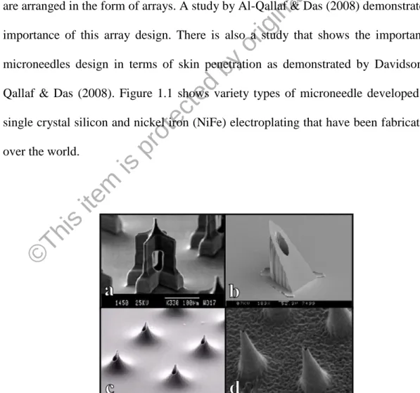
Different shapes of microneedle have been developed in micro-electro- mechanical system (MEMS) technology using a variety of different materials. It has been reported that microneedles have been fabricated in metals, silicon, silicon dioxide, polymers, glass and other materials. There are two main categories of microneedles, which are solid microneedles and hollow microneedles. Hollow microneedles allow a better control of drug administration in terms of amount and time compared to solid microneedles. For both types, to guarantee an adequate of drug delivery, microneedles are arranged in the form of arrays. A study by Al-Qallaf & Das (2008) demonstrates the importance of this array design. There is also a study that shows the importance of microneedles design in terms of skin penetration as demonstrated by Davidson, Al- Qallaf & Das (2008). Figure 1.1 shows variety types of microneedle developed from single crystal silicon and nickel iron (NiFe) electroplating that have been fabricated all over the world.
Figure 1.1: Microneedles developed from single crystal silicon reported by: a) (Griss &
Stemme, 2003); b) (Gardeniers et al., 2003); c) (Stoeber & Liepmann, 2005); and NiFe electroplating: d) (McAllister et al., 1999).
© Thi
s i tem
is pr ot ec ted by
or igi nal
c opy
right
4
A number of necessities are needed in microneedle features in order to construct a painless microneedle. First and foremost, the microneedle is supposed to be strong and sharp enough to pierce the epidermis layer without failure. Secondly, to minimize the contact between microneedle and nerves, the length of the needle needs to be controlled by the base of the needle. Besides that, due to the fact that the skin is elastic and there is random blood vessels distribution in skin, it is important for the microneedle design to have a high aspect ratio and arrayed structures. Finally yet importantly, each needle of the array should have small-penetrated area to reduce pain and skin damage (Moon & Lee, 2003). Microneedle can be integrated with micropump, biosensor, microelectronic devices and microfluidic chips. These devices are being rapidly developed by researchers around the world to fulfill the demand of biomedical field.
1.3 Problem Statement
As MEMS devices especially microneedles develop in complexity, there is a greater need in reducing the amount of time taken for MEMS designers to analyze their design before they proceed into the fabrication process. Most of the time taken by a MEMS designer is spent in the initial conceptual stages of design by using the efficient computer-aided design (CAD) tools. At the moment, there are variety of MEMS CAD programs that offer MEMS designers pre-configured cell libraries with reusable apparatus such as Cadence, IntelliSuite and ANSYS (Cobb & Agogino, 2010).
However, there is issue for the designer on how and when these components should be used. In other words, these simulation tools are not efficient during the simulation
© Thi
s i tem
is pr ot ec ted by
or igi nal
c opy
right
5
process of design as they require detailed modeling data and take up hours or even days to analyze one design. This situation, if not being handled properly can become a serious problem to MEMS industry.
Microneedle structure design is one example of the MEMS design that involves various parameters and complex set of design requirements. To the best of author’s knowledge, most of the previous works focused only on the design of the microneedle itself and/or the fabrication process for the microneedle. Work on how to reduce the amount of time taken to complete one microneedle design is virtually nonexistent.
There is a need for simulation and design tools that can provide faster concept generation during the initial stages of the design process. The simulation process of microneedle or other complex MEMS design might become simple and easy if we have a systematic optimization tool. The use of artificial intelligence (AI) approach has been effectively employed to deal with reliability optimization problems. Therefore, this research investigates the most appropriate method to optimize the microneedle structure in a lesser time.
1.4 Research Objectives
In this research, the main objective is to design and optimize the microneedle structure by a given design variables. Other than that, several more objectives must be achieved. The objectives are listed below:
i. To maximize the flow rate of the fluid flow through microneedle channel and to minimize the total deformation, strain energy and equivalent stress of microneedle according to specified requirement by using two artificial
© Thi
s i tem
is pr ot ec ted by
or igi nal
c opy
right
6
intelligence (AI) techniques which are particle swarm optimization (PSO) and genetic algorithm (GA).
ii. To improve the effectiveness of the microneedle optimizer by combining PSO technique with GA technique, known as a hybrid PSO-GA method (HPSOGA).
iii. To compare the PSO, GA and HPSOGA in terms of the performance of microneedle structure.
1.5 Research Scope
The research starts by studying and understanding about the structure and different layers of human skin. The information on the thickness and the sensitivity of human skin is very important to determine the design variables of microneedle. The optimization study for maximization of flow rate and minimization of total deformation, strain energy and equivalent stress of microneedle are the main focus in this research. The MEMS CAD tool, ANSYS is used to analyze and simulate the microneedle structure in this research. The approach of AI techniques which are PSO and GA are proposed to optimize the design of microneedle structure. In order to improve computation competency, hybrid optimization algorithms are investigated by combining the PSO with GA. The developments of algorithm part in this research are conducted in MATLAB environment.
© Thi
s i tem
is pr ot ec ted by
or igi nal
c opy
right
7 1.6 Thesis Organization
This research thesis is divided into five sections, which are Chapter 1 - Introduction, Chapter 2 - Literature review, Chapter 3 - Methodology, Chapter 4 - Result and Discussion and Chapter 5 - Conclusion. The contents of each chapter are shown as follow:
i. Chapter 1 presents the overview of microneedle, problem statement, research objectives, research scope and the organization of thesis.
ii. Chapter 2 explains the previous studies that are related to the research. It covers a review on the material that is required for designing the microneedles, the parameters that are suitable for the design, the shape of the microneedle, the fabrication process flow, types of microneedle and review on human skin. This chapter also explains the usage of artificial intelligence (AI) as the optimization tools in engineering field especially MEMS and biomedical area. The process of particle swarm optimization (PSO) and genetic algorithm (GA) are also discussed in detail.
iii. Chapter 3 discusses the methodology of the research that covers the most preferred method and procedure used in carrying out the project. Besides that, a brief description on a systematic approach, tools and techniques applied in order to achieve the given research objectives.
iv. Chapter 4 illustrates the optimization results of microneedle structure by using various optimization methods. Important findings are presented in a comprehensive manner and the research objectives are reviewed to ensure the goals set are satisfied. The results obtained are discussed in detail.
© Thi
s i tem
is pr ot ec ted by
or igi nal
c opy
right