The aim of this project is to develop a working prototype, the Vibration Energy Harvesting System (VEHS), which will be used to convert the vibration energy generated by traffic vibrations on the road pavement into electricity. Among the techniques available for the conversion of vibrational energy into electrical energy is the use of the concept of electrostatic, piezoelectric and electromagnetic induction. Since it is easy to maintain a strong magnetic field using strong permanent magnets, electromagnetic induction was chosen as the appropriate approach for this project.
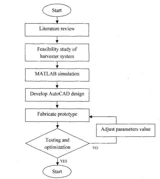
After that, the prototype is manufactured and the testing is carried out to observe the performance of the device. The prototype is placed on vibration generator where its frequency and acceleration can be adjusted. The result of open-loop and closed-loop tests of the prototype is summarized in the graphic representation.
Of the many people who have been extremely helpful in the preparation of this dissertation, I am especially grateful to Dr. Nursyarizal Mohd Nor and Dr Mohd Haris Md Khir for their help and support in guiding me to its successful completion. Last but not the least, I offer my regards to those who support me, especially all my friends and technicians in the Department of Electrical and Electronic Engineering for contributing their help and ideas to this project.
CHAPTER!
INTRODUCTION
- Background
- Problem Statement
- Objective
- Scope of Study
Since the solar energy harvester relies on the intensity of sunlight projected onto the solar panel, cloudy weather or rainy conditions will disrupt the amount of sunlight reaching the solar panel. Nowadays, various types of vibration-based energy harvesters are available for different purposes [8]. Moreover, it also seems feasible in the future as an alternative energy source instead of the costly and exhausted fossil fuel-based generation method.
On the other hand, some people have already started to find another source of energy to reduce the dependence on fossil fuel. To capture small amounts of vibration energy produced from the vehicles at the moment it passes through the vibration energy harvester to produce electricity. To design and manufacture a vibration based energy harvester to harvest energy produced by vehicles on the roads.
To characterize, analyze and optimize energy harvester performance through testing, monitoring and data collection. Investigate the causes of vibrations produced by road traffic and the transmission medium of the vibration.
CHAPTER2
LITERATURE REVIEW
Traffic Vibration
In order to make full use of this abundant vibration energy, an innovative idea, the vibration energy harvester, was designed to convert unused vibration energy into electrical energy [7, 8, 9]. A possible use of this device is powering electronic circuitry and other possible applications within the same power specification range. Kinetic energy from road traffic is converted into electrical energy using the principle of electromagnetic induction and the law of vibration.
Vibrational energy from the road is translated into a kinetic energy that will create a displacement in the system in relation to time, causing a change in the magnetic field, which in turn produces electricity [10]. In addition to this, a booster circuit and a storage circuit will be added designed for more efficient energy supply. Booster is used to increase the DC voltage, rectified from the output of the energy harvester, while a storage circuit is used to store the generated electrical energy for future use.
During low production, the stored energy can be used to cover the lack of power from the mains. This energy harvester also promotes the use of green technology as an alternative to power electrical devices with almost zero pollution emissions.
Vibration-to-Electrical Energy Harvester
- Vibration Law
- Electromagnetic Indnction Law
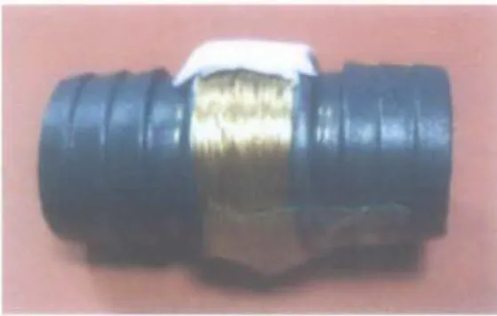
The piezoelectric effect is a reversible process, if a voltage is applied to a strained piezoelectric material, the shape of the solid will change slightly. Meanwhile, electromagnetic based energy harvesters use magnetic field to convert mechanical energy into electrical energy [7-10]. A coil attached to the oscillating mass passes through a magnetic field established by a stationary magnet.
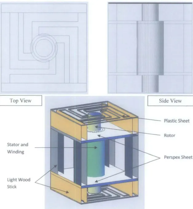
Since it is quite easy to maintain a strong magnetic field with a permanent magnet and the system is quite robust, electromagnetic vibration power generators are preferred in many applications. ii. Simply put, spring oscillation is the act of transferring kinetic energy and potential energy. This project also applies the same concept as mentioned above, where the base of the prototype will be subjected to an external force (road vibration) to induce the oscillation of a spring attached to a mass.
This device will be placed under forced harmonic excitation and the response of the system is called harmonic response [18]. Consider the system shown in Figure 6, a system in which the base is subjected to harmonic force with atmospheric air as the damping element, where y(t) denotes the displacement of the base and x(t) the displacement of the mass with respect to its base . static equilibrium position at time t. butt vibration due to spring displacement. A changing magnetic field can also induce a current in a conductor and the current is called an induced current because it is created by the changing magnetic field.
But as soon as the magnet is moved back and forth from the coil respectively, a voltage and a current are induced [19]. When the magnet is moved towards the coil, the magnetic field through the coil increases and thus induces a current. Magnetic flux is a measure of the amount of magnetism and it deals with the magnetic field and the surface it passes through.
The flux depends only on the part of the magnetic field that is perpendicular to the area it passes through. So if the direction of the magnetic field is not perpendicular to the area, the equation for flux becomes. The changes in the magnetic flux as the mass oscillates will induce an EMF at the end of the coil [19, 20].
![Figure 2: Schematic of an electrostatic harvester for vibration energy [12]](https://thumb-ap.123doks.com/thumbv2/azpdforg/10278744.0/19.853.279.564.165.409/figure-2-schematic-electrostatic-harvester-vibration-energy-12.webp)
Existing Electromagnetic Energy Harvester Design
CHAPTER3 METHODOLOGY
Simulation Results
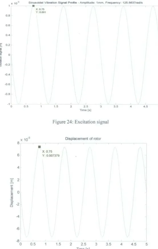
When the frequency of the excitation signal is increased above the value of the natural frequency, the response of the system will deviate by 180°. The amplitude of the rotor displacement is optimal when the frequency of the excitation signal is equal to the natural frequency of the device. The speed of the mass and the value of the induced EMF depend on the value of the damping element, the stiffness of the plastic plates and the mass of the rotor.
Note that as the stiffness of the plastic plates increases, the value of EMF generated will also increase, but only up to a certain point. When the spring constant is further increased, the value of EMF generated decreases. It is clear that, as shown in Figure 29, when the value of the mass is increased, the amount of EMF generated will also increase accordingly.
However, similar to the case in Figure 28, the value of the EMF will begin to decrease when the mass of the rotor reaches a certain point. So, as the stiffness value of the plastic sheet increases, the value of the natural frequency increases, the frequency ratio decreases (but still exceeds one) while the displacement transmissibility increases. When the mass increases up to 0.02 kg, the value of the natural frequency decreases, the value of the frequency ratio and the displacement transmissibility increased.
Increasing the frequency value of the excitation signal will increase the frequency ratio and displacement transferability. This case remains true if the value of the frequency of the excitation signal is lower than or equal to the natural frequency of the device. Thus, at an excitation signal frequency lower than or equal to 20 Hz, the system response will be normal.
However, when the frequency of the excitation signal exceeds 20 Hz, the system response will deviate 180° from the normal state. The frequency of the excitation signal should be kept less than or equal to 20 Hz to maintain the system response in normal condition. It is clear that the value of the estimated EMF is directly proportional to the number of turns of the coil.
In Figure 34, it is observed that the value of the peak-to-peak voltage increases with the increasing value of the frequency of the excitation signal until the frequency reaches 20.2 Hz. After this point, the peak-to-peak voltage value continues to drop as the frequency of the excitation signal exceeds the natural frequency of the device.
CHAPTERS
CONCLUSION AND RECOMMENDATION
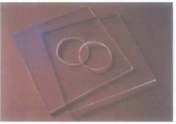
For example, the plastic sheet used in this project to help oscillate the rotor when an external force is applied to the prototype could be replaced with a more sensitive and flexible material such as polymer. However, polymer is very difficult to get in the market and very expensive compared to the plastic film which can be recycled from PP food container. More features can be added to the existing design to increase the marketability of the product.
Apart from its main objective of developing an alternative and pollution-free vibration-based energy harvester, this project is also intended to make people aware of green technology and the importance of utilizing the energy available in the environment. The prototype can be further improved by reducing its size while maintaining its ability to produce the same or greater amount of output. In addition, the application of the prototype is not limited to placing it just on the side of the road.
The vehicle itself produces vibrations while in motion, and this combine can be positioned to harvest this vibrational energy.
Cao, et al., ''Electromagnetic Energy Harvesting Circuit with Feedforward and Feedback DC-DC PWM Boost Converter for Vibration Energy Generator System'', IEEE Transactions on Power Electronics, Part II] Torres, E,O., Rincon-Mora, G.A., "Electrostatic Energy Harvester and Li-ion Charging Circuit for Microscale Applications,” Georgia Tech Analogue and Power IC Design Lab., Atlanta. 12] Sterken, T., Altena, Geert, Foirini, P., and Puers R ., "Characterization of an electrostatic vibration harvester", Dans Symposium on Design, Test, Integration and Packaging of MEMS/MOEMS-DTIP 2007, Stresa, Lago Maggiore, Italy, 2007.
13] Piezoelectric Transducers, 2011, 30 May 2011, from http://www.ndt-ed.org/EducationResources/CommunityCollege!Ultrasonics/EquipmentTrans/piez otransducers.htm. 16] Energy Harvesting as an Enabling Factor for Bridge Monitoring, 2011, 3 June 2011, from http://www.intelligent-systems.info/bridge.htm.
APPENDICES
![Figure 1: Road traffic vibration [ 5]](https://thumb-ap.123doks.com/thumbv2/azpdforg/10278744.0/17.856.142.677.588.786/figure-1-road-traffic-vibration-5.webp)
![Figure 4: An electromagnetic energy harvester attached to a bridge [16]](https://thumb-ap.123doks.com/thumbv2/azpdforg/10278744.0/20.853.289.555.384.696/figure-4-electromagnetic-energy-harvester-attached-bridge-16.webp)
![Figure 6: Simplified prototype spring-mass-damper model [17]](https://thumb-ap.123doks.com/thumbv2/azpdforg/10278744.0/22.853.157.682.309.506/figure-simplified-prototype-spring-mass-damper-model-17.webp)
![Figure 8: Magnet is moved back and forth [19]](https://thumb-ap.123doks.com/thumbv2/azpdforg/10278744.0/24.861.158.705.761.970/figure-8-magnet-moved-forth-19.webp)
![Figure 12: A linear generators with iron-permanent magnet rotor [9]](https://thumb-ap.123doks.com/thumbv2/azpdforg/10278744.0/27.861.285.555.492.750/figure-12-linear-generators-iron-permanent-magnet-rotor.webp)