By now, the photothermoinduced crystallization and properties of the PTR glass have been sufficiently well investigated. Schematic representation of the volume Bragg grating (left) and TEM image of the actual grating fringe (right).
Thermal stability of volume Bragg gratings in chloride PTR glass
Figure 12(b) shows the angular selectivity contours after laser bleaching of VBG under different LD diode beam intensities. Dependence of the change in temperature and Bragg wavelength on the power density of the pumping source.
Conclusions
Manifestations of the valence states of Ce3+ and Ce(IV) in the UV-absorption spectrum of cerium-doped photo-thermo-refractive matrix glasses. Fluorescent clusters in chloride photo-thermo-refractive glass by femtosecond laser bleaching of Ag nanoparticles.
TOP 1%
Introduction
He devised a way to use the monoenergetic (monochromatic) scattering of X-rays from objects to interfere with directly delivered X-rays of the same wavelength to create an interference pattern that encoded information about the object's transparency, texture, and spatial arrangement, which could be recorded and, when viewed under similar lighting, reveal a reconstructed image of the object. The limited spectral purity of the source only permitted an illumination setup with the source, filter, transparent object, and film in a straight line. They published an article with photographs of images they made using this technique that clearly demonstrate the potential for realistic 3-D images that can be viewed without any optical aid [3].
Now the production of suitable emulsions has added a new requirement: it must resolve the interference pattern, which, due to the change in beam geometry, has become much finer, in some respects, down to half (or less) the wavelength of the selected laser light. Lippmann created such an emulsion in order to record the interference pattern of ordinary light interfering with itself upon reflection from the surface of the emulsion in contact with the mercury mirror. This research considers some alternatives, but is interested in variations of the latter, including some recent advances.
The range of emulsion types
- Information recording types and diffraction efficiencies
- Photopolymer, photoresistive, and photothermoplastic emulsions
- Photochromic materials
- Dichromated gelatin emulsions
- Silver halide gelatin emulsions
Underlying these goals is a fundamental conflict well known in conventional photography: the inverse relationship between resolving power/grain size and sensitivity—the finer the grain, the less sensitive the emulsion. The illumination angle can be selected to use a phase-reversed version of the hologram. In 1905, Lippmann commented [31], referring to his interference color photographic process, which works on the principle of the reflection hologram: "The question arose in my mind, whether this transitory effect of moisture could not be permanently replaced by a solid, stable body.".
When we poured a solution of silver nitrate (20%) over the dry iodized film, the colors became extremely brilliant and the plates did not lose their striking character after drying." The images were so bright that complementary colors were visible when viewed in transmission instead of reflections, and they were brilliant. The first way involves the reduction of silver halide crystals that contain the generated excited electrons. There is a very slight color shift to red, indicating that there has been very slight swelling of the emulsion due to processing.
Conclusions
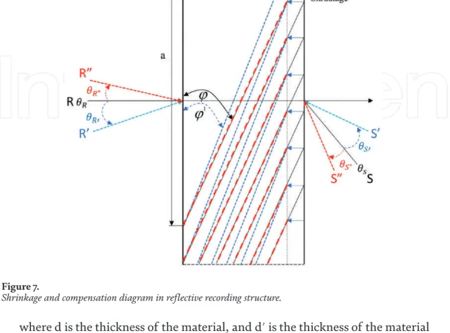
This chapter is distributed under the terms of the Creative Commons Attribution License (http://creativecommons.org/licenses/ . by/3.0), which permits unrestricted use, distribution, and reproduction in any media, provided the original work is properly cited. It also explores the Bragg angle shift phenomenon caused by shrinkage of the recording materials. In other words, AR is one of the forms in which VR is combined with reality.
The main parts of optical components are diffractive optical element (DOE) [6, 7] and holographic optical element (HOE) [8, 9]. While the HOE can control the angle of the two recording beams to record the interference pattern of the beams on the recording materials, so it can be manufactured more easily than DOE production. He then investigates the phenomenon of Bragg angle shift caused by the shrinkage of the recording materials.
Full-color HOE for waveguide-type HMD
As shown in Figure 4(b), the incidence angles of the recording material θ 1 and θ 2 determine the angle of total internal reflection θ t = θ 1 + θ 2. The angle of total internal reflection must be greater than the critical angle of the waveguide. Performance of colored HOEs for (a) single-layer structure, (b) triple-layer structure, and (c) double-layer structure (RG/B) (d) double-layer structure (R/GB). on both sides of the wedge waveguide.
The angle of total internal reflection is directly related to the thickness of the waveguide structure. The schematic configuration of a wedge-shaped holographic waveguide HMD, (b) designed angle of the light path within the wavelength. And the optical efficiency of the full-color HVG using the GBR recording process was measured at 31%.
Full-color HOE for AR application
- Measurement and compensation of shrinkage
- Optimization of recording full-color HOE
- Full-color image for HUD with HOE lens
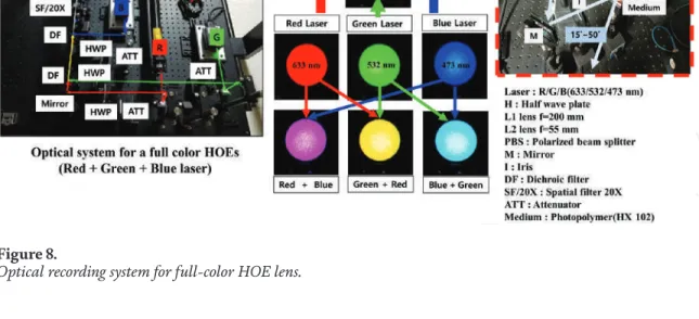
The diffraction efficiency is the performance of the HOE, is measured with different illumination energies and different shooting angles. When shooting the full-color HOW, the uniformity of the laser beam of three wavelengths will determine the color uniformity of full-color images. Especially the shooting angles and shooting intensities are very important to determine the diffraction efficiency of the HOE.
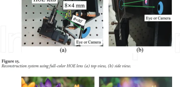
But the diffraction efficiency of the recording material depends on the recording angle, it is important to choose the optimal recording angle considering the diffraction efficiency. In other words, the functions of the optical lens are registered in the HOE and can be used as the HOE lens. The system is configured such that the OLED microdisplay is located in the focal length of the HOE lens and can be viewed using the HUD method.
Conclusions
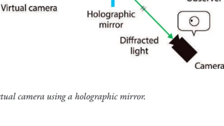
Full Color Holographic Optical Elements for Augmented Reality Display DOI: http://dx.doi.org/10.5772/intechopen.85767. A holographic mirror is a reflection-type holographic optical element that acts as an off-axis mirror. It realizes an upright transparent screen that functions as a virtual image display and a virtual camera.
Such a screen enables the realization of attractive applications based on virtual images, such as Pepper's ghost, with only a thin optical system. Keywords: holographic optical element, virtual image display, virtual camera, dispersion compensation, volume hologram, Pepper's ghost. A holographic optical element (HOE) is capable of implementing various flexible optical functions on a thin, flat, transparent film based on wavefront recording and reconstruction.
Holographic Pepper’s ghost
To realize virtual image-based applications with only a thin optical system, we proposed a novel optical system that combines an HOE-based mirror called a holographic mirror, dispersion compensation optics, and a digital projector [21]. In this chapter, we describe the background of virtual image-based applications in Section 2, the holographic mirror illumination method in Section 3, the concept and verification of the proposed virtual image display in Section 4, and the concept and verification of the proposed virtual camera in Section 5. 0.5772/intechopen.85600.
For example, it is possible to realize a holographic mirror which functions as an off-axis mirror by Bragg diffraction. The holographic mirror can be used for a straight virtual image display as mentioned above and shown in Figure 1(b). A problem in applying a holographic mirror to a virtual image display is the chromatic dispersion caused by diffraction, which results in spatial blurring of the virtual image.
Exposure of a holographic mirror using a hologram printer
The appearance of a virtual image of a white paper including a star symbol formed with an exposed holographic mirror is shown in Figure 3(b).
Virtual-image display using a holographic mirror and dispersion-compensation optics
We also placed an A4 size diffuser screen and a holographic mirror described in the previous section. We set the distance between the diffuser and the holographic mirror to 600 mm, and that between the DOE and the diffuser to 600 mm. Optical design of the virtual image display with a holographic mirror and diffuser-based blur compensation optics.
Projected images on a distributor and (b) virtual images displayed by the projected virtual image displayed without and with a DOE. In addition, since the camera focused on the virtual mirror, the holographic mirror display was uncertain. These observations show the displacement of the axial position of the holographic mirror acting as a screen and the displayed virtual image.
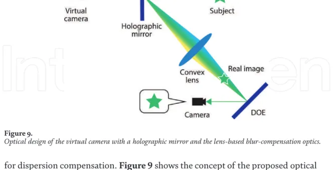
Virtual camera using holographic mirror and dispersion-compensation optics
As a result of the insertion of the lens, a true image of the subject is optically formed between the lens and the DOE. Since the light is not diffused in the optical system, the light utilization efficiency is higher than that of the diffusion-based display system, but on the other hand, the acceptable camera positions for image capture are limited. Optical design of virtual camera with a holographic mirror and lens-based blur compensation optics.
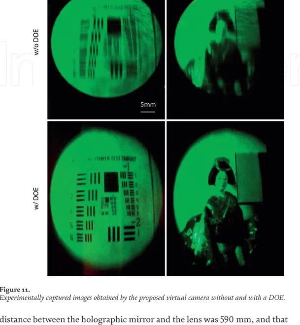
Without a DOE, the chromatic dispersion of the holographic mirror degraded the vertical spatial resolution of the captured image. By visually evaluating the images of a resolution chart, the vertical spatial resolution improved from 0.80 to 1.46 cycles/mm. The result with a manikin indicates the feasibility of the proposed optical system for visual video communication systems for human users.
Conclusion
We proposed two optical systems that integrate DOE-based dispersion-compensation optics, imaging equipment and a holographic mirror. We experimentally verified the realization of the concepts on the virtual image display and the virtual camera, and the effectiveness of the dispersion compensation. The proposed systems can be applied to upright, thin, translucent screens for virtual image displays and virtual cameras.
The system can e.g. used for virtual image-based interactive displays and video communication systems where the display can be integrated with environmental objects such as flat walls and display panels. 4 Research fellow in the Japan Society for the Promotion of Science, Chiyoda-ku, Tokyo, Japan.