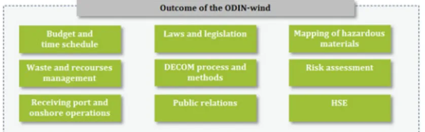
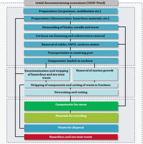
The assessment of the decommissioning process requires consideration at many levels and of many sub-processes. At the top, Fig.22.1 shows the planning process, which must assess the entire process of decommissioning - i.e. - the shutdown planning, which is the work explained as a whole in this chapter. Although experience shows that input from decommissioning is not as important as other considerations - such as structure, installation scenarios, etc.: : : - the decommissioning input can still have an important influence on the final decision.
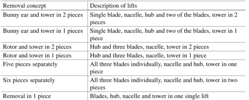
The final decommissioning assessment should be updated well in advance of the actual decommissioning of the wind farm. Depending on which part of its life cycle the OWF is in – design, operation or end of life – the regulatory process is slightly different. Bunny ear and turret in 2 pieces Single blade, nacelle, hub and two of the blades, turret in 2 pieces.
Rabbit ear and tower in 1 piece. Single blade, gondola, hub and two of the blades, tower in 1 piece.
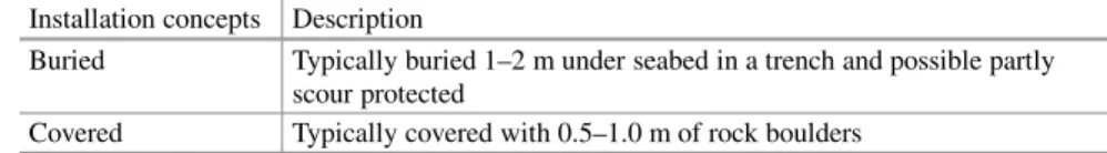
Cable Removal
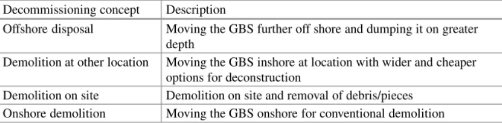
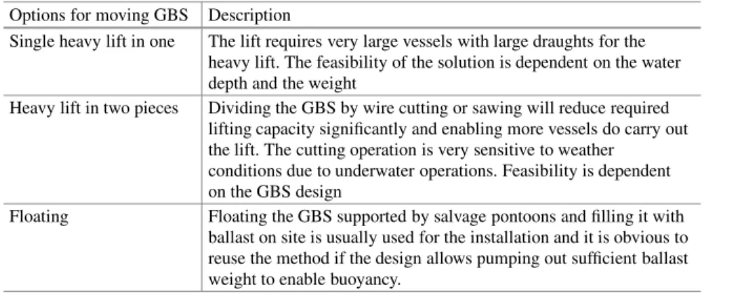
Single heavy lift in one The lift requires very large vessels with a large draft for the heavy lift. Heavy lifting in two pieces Splitting the GBS by wire cutting or sawing will significantly reduce the required lifting capacity and enable more vessels to do the lifting. Floating Floating GBS supported by salvage pontoons and filling with ballast on site is normally used for installation and it is obvious to reuse the method if the design allows pumping out sufficient ballast weight to enable buoyancy.
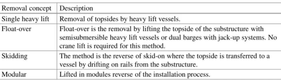
Float-over Float-over is the removal by lifting the top of the substructure with semi-submersible heavy lift vessels or double barges with jacking systems. Slip The method is the reverse of slip-on where the topside is transferred to a vessel by drifting off the understructure on rails. The logical solution for removing the top uses the same concept as for the installation.
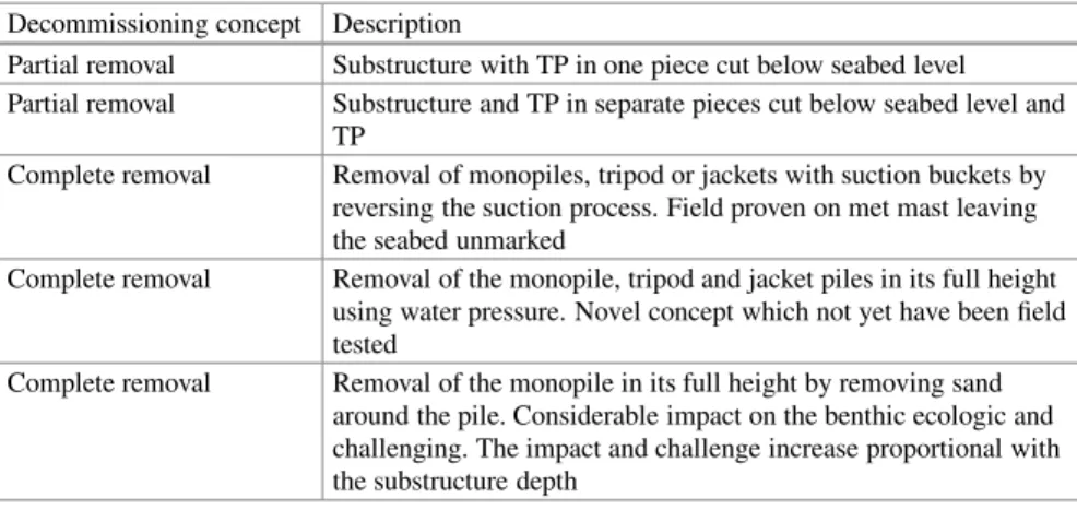
Regardless of the removal concepts, separating the top and substructure requires a cut at stub pipe sleeves and all welded connections. Directly "Brute forced" (if rock covered) - the cable is pulled first from the J-tube and then from the rock layer. The solution depends on the regulatory obligations and/or the economic balance between the cost of recycling and the scrap value.
In some cases, the possible re-powering and re-use of cables will determine the best solution. The best solution for the storage of the cable is interdependent on transport distance and unloading facilities and if direct loading to scrap yard is relevant. For the spraying operation and the fixing of the cable to the crane hook, an ROV can be applied.
Met Mast
Vessels and Ports
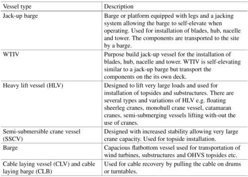
Vessel Types
Vessel Suitability
The physical character of the structures and the proposed method of removal will lead to a number of requirements for the vessels to be used. As a key factor in the planning stage, the vessels' operational limits with regard to environmental burdens must be taken into account. Furthermore, the logistics planning should take into account cargo area, transport/transport speed, length, draft, width and other such factors to align port requirements and get realistic cost estimates.
Ports
Removal Sequence and Weather Windows
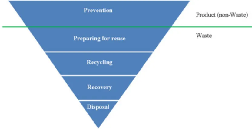
Waste and Material Management
- Reuse of Components
- Recycling
- Incineration
- Deposit
Material taken to land by the wind farm will be reused, as far as possible, recycled or incinerated for energy recovery. The circular economy trend will also affect the offshore wind industry, and the design of modules will over time be easier to dismantle, refurbish and reuse. For rubber, plastic and glass fibers, or other compounds and epoxy, recycling is possible, but depending on the quality and composition of the specific products.
Due to the anti-fouling agent on the substructure, these can become contaminated with the active ingredients of the anti-fouling agent. Due to the organic content in the material, it is possible that the material can be used as other types of sludge. If rubber, plastics and glass fibres, or other composites and epoxy cannot be recycled, they may be incinerated for energy purposes.
It is known that a large amount of glass fiber can cause problems for the filter system of the incinerators and that the emission of dioxin can increase. Although a method exists for the recycling of mainly rigid PVC, it is not feasible for ONFs. In wind turbines, PVC is sometimes used as cores in the blades and must first be separated from the fiberglass before it can be recycled, which is currently still difficult.
It is an area of innovation, as these materials are currently mainly incinerated or landfilled depending on their content. If the marine fouling on these materials is heavily contaminated by anti-fouling agents, the composites will have to be disposed of. In some cases this can be treated (for example through the use of chemicals); otherwise depositing is the only option.
Cost Estimation
PVC is a problematic compound because it can contain phthalates or heavy metals - and if it is burned in a waste incineration plant, the amount of slag produced will increase significantly. The budget should be accompanied by a time schedule which will naturally appear as the methods are assessed. The schedule should show the different phases of the decommissioning work which will naturally be undertaken in the most suitable part of the year in terms of weather, based on the implementation of sequence and removal windows.
ODIN-WIND: The Tool
The ODIN-WIND tool is described in more detail in the EWEA paper "Preparing for the future - the full decommissioning process" (Gjødvad2015).
Conclusions
Wind Turbine Blades: An End of Life Perspective
- Introduction
- Wind Turbine Blades: Structure and Materials
- Industrial Scale Solutions .1 Refurbishment
- Incineration
- Mechanical Grinding
- Occasional Solutions .1 Large Sections
- Construction Element
- Solutions on a Research Stage
- Conclusion
The amount of wind turbine blade material expected to reach end-of-life in the coming years is shown in Fig.23.2. This section will detail some of the project results and other existing solutions for the end-of-life rotor blade. As the trend moves towards longer blades, blade weight and stiffness become an issue.
As part of the GenVind project, the residual strength of a wind turbine blade composite material after being fatigue tested was investigated. The goal was to get an idea of the quality of real end-of-life composite laminates from blades. The following section examines solutions for end-of-life wind turbine blades on an industrial scale.
A study conducted in Germany by Sayer et al. 2009) investigated the effect of lifetime on wind turbine blades based on comparison of blade performance after 20 years of use. Grinding wind turbine blade material has a significant disadvantage; it does not take advantage of the original structural properties of the composite and significantly reduces the value of the material. These solutions take advantage of the material's capacity, but are difficult to implement on an industrial scale.
This solution offers the possibility of using good quality and structural performance of the blade material. On the other hand, the number of possible applications is limited by the complexity of the blade structure, and mass production is almost impossible. The blades can also cut structural elements such as beams, panels and curved elements.
The potential of these recycling solutions can be compared in terms of: the amount of reprocessing involved, the value of the material produced and the number of possible uses. However, if we consider the number of possible applications that can be made from the produced material, solutions involving heavy processing may be more interesting.
This section discusses recycling solutions that are currently used or may be used. Considering the amount of reprocessing required in the different solutions presented, refurbishment is certainly the one that requires the least compared to a process such as mechanical grinding or supercritical fluids. Comparing the value of the material produced, refurbishment, by renewing the blades that will produce electricity for a few more years, is likely to be of higher value than expensive reclaimed fiberglass with low mechanical properties.
Acknowledgments The authors would like to thank the innovation consortium GenVind (“National initiative around gene applications af plastic composite”): especially Karin Magelund Møller and Jacob Boutrup from LM Wind Power for providing a wind turbine blade for this study. Open Access This chapter is distributed under the terms of the Creative Commons Attribution-NonCommercial 4.0 International License (http://creativecommons.org/licenses/by-nc/4.0/), which permits any noncommercial use, duplication, adaptation, distribution, and reproduction. in any medium or format, as long as you give appropriate credit to the original author(s) and the source, provide a link to the Creative Commons license and indicate whether changes have been made. The images or other third-party material in this chapter are included in the work's Creative Commons license, unless otherwise indicated in the credit line; if such material is not included in the work's Creative Commons license and the respective action is not permitted by statutory regulations, users will need permission from the licensee to duplicate, adapt or reproduce the material.
Duflou JR, Deng Y, Van Acker K et al (2012) Do fiber-reinforced polymer composites offer environmentally friendly alternatives? Kennerley JR, Kelly RM, Fenwick NJ et al (1998) The characterization and reuse of glass fibers recycled from scrap composites through the action of a fluidized bed process. Oliveux G, Bailleul JL, Le Gal La Salle E (2012) Chemical recycling of glass fiber reinforced composites using subcritical water.
Sayer F, Bürkner F, Blunk M et al (2009) Influence of loads and environmental conditions on material properties during rotor blade life. Schmidt A (2006) Life cycle assessment of electricity produced by onshore wind farms based on Vestas V82-1.65 MW turbines. Sørensen BF, Jørgensen E, Debel CP et al (2004) Improved large fiber composite wind turbine blade design based on scale effects studies (Phase 1) Summary Report Risø-R-1390.