The approach to the study was, first, to investigate the effects of internal pressure and pipe loads at the shell-to-nozzle connection. The results obtained were used to develop appropriate procedures for the design of vessels under external atmospheric pressure and pipe loads.
PRESSURE VESSELS
Introduction
Design of Pressure Vessels
- Design pressure
- Design temperature
For standard vessels, the design temperature is the maximum temperature of the working fluid plus an amount added for safety, or the minimum temperature of the working fluid if the vessel is designed for low temperature operation. Adequate design temperature is critical to ensure the safety of the vessel design.
Design of thin cylinders - ASME Code
The required design temperature per the Code shall not be less than the average metal vessel wall temperature expected under operating conditions and calculated using standard heat transfer equations or actual measurements.
STRESSES IN PRESSURE VESSELS
Introduction
The work done by the moments is t x (moment) X (angle between the . sides of the member after bending). An increase in the size of the nozzle also increases the stress at the shell-to-nozzle connection.
![Figure 2-1 : Membrane stresses in vessel. Obtained from Harvey[20]](https://thumb-ap.123doks.com/thumbv2/pubpdfnet/10629871.0/19.828.125.777.416.1070/figure-membrane-stresses-in-vessel-obtained-from-harvey.webp)
Membrane Stresses in Vessels under Pressure
Thin Plate theory
- Strain-curvature relationships
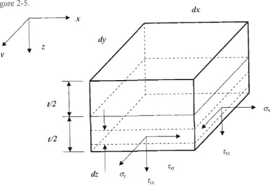
- Stress Resultants
The plane shown in Figure 2-5 represents the center of the plate or the neutral surface. The moments Mx and My per unit length are positive when they act at the center of the plate.
Thin Shell theory
The thickness of the shell T, will always be assumed to be small compared to the radii of curvatures, therefore z/rx can be neglected. Since the thickness of the shell is very small, the lateral sides of the element can be considered as rectangles.
![Figure 2-9: Deformed middle surface. Obtained from Timoshenko[l]](https://thumb-ap.123doks.com/thumbv2/pubpdfnet/10629871.0/30.828.278.607.151.662/figure-2-9-deformed-middle-surface-obtained-timoshenko.webp)
Stress Theories of Failure
- Maximum Principal Stress Theory
- Maximum Shear Stress or Tresca Theory
- Distortion Energy or Von Mises Theory
The maximum shear stress is equal to half the difference of the maximum and minimum principal stresses. Similarly, the maximum shear stress for a tensile test is equal to half the normal stress at yield.
Finite Element Stress Analysis
- Finite Element method
According to the energy method, the variation in the potential energy of the plate shown in figure 2-12 is from equation 2.57. The general procedure for solving plate or shell problems by the finite element method is summarized as follows.
![Figure 2-12 : Rectangular Finite Element. Obtained from Bulson and AlIenl17]](https://thumb-ap.123doks.com/thumbv2/pubpdfnet/10629871.0/39.828.185.779.105.273/figure-12-rectangular-finite-element-obtained-bulson-alienl17.webp)
VESSELS UNDER INTERNAL PRESSURE AND PIPING LOADS
Introduction
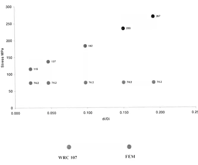
The above equation shows that the smaller the area, the higher the stress, so the stress induced in the shell due to compressive and thrust loads on the nozzle must be much greater than the membrane stresses calculated by WRC 107 and 297. The nozzle is reinforced in accordance with ASME Code VIII Div 1 based on internal design pressure.
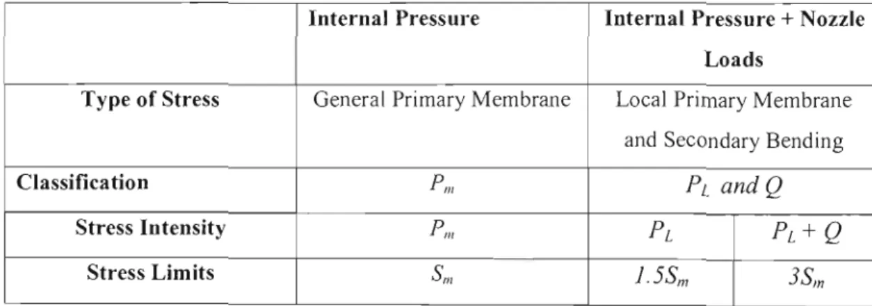
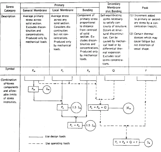
ASME VIII Div 2 Classification of Stresses
At the shell-to-nose junction there is a transfer of loads from the nose to the shell, therefore, the membrane stresses produced at this point are, by definition, local primary membrane stresses. Bending stresses as defined in the ASME Code are secondary stresses.
Stress Limits
Therefore, the allowable stress limit for the local pnmary membrane stress intensity must be the yield strength of the material. The ASME code calculates the allowable or design stress as a fraction of the material's yield strength and ultimate tensile strength.
Calculation of Stress Intensities
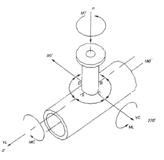
WRC Bulletin 107
- Stresses Resulting from Radial Load, P
- Circumferential Membrane Stress
- Circumferential Bending Stress
- Longitudinal Membrane Stress
- Longitudinal Bending Stress
- Stresses Resulting from Circumferential Moment, Mc
- Circumferential Membrane Stress
- Circumferential Bending Stress
- Longitudinal Membrane Stress
- Longitudinal Bending Stress
- Stresses Resulting from Longitudinal Moment, M L
- Circumferential Membrane Stress
- Circumferential Bending Stress
- Longitudinal Membrane Stress
- Longitudinal Bending Stress
- Stresses Resulting from Torsional Moment, M T
- Stresses Resulting from Shear Loads, Vc and V L
- Sign Convention
- Stress Intensities
The longitudinal bending stress due to radial load is given by the following equation. Using the rand parameters fJ and the dimensionless curve lA, the values for are Mc / RlIlfJ.
Numerical Results
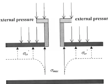
This clearly illustrates the thrust load effect of the internal pressure occurring at the shell-nozzle junction. The rotation of the axial side DC with respect to the x-axis can be expressed as an angle. Several formulas have been developed to calculate the deflection pressure of vessels under external pressure.
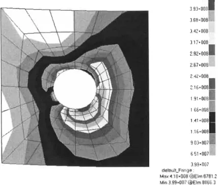
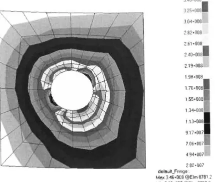
At the shell-to-nose junction the cross-section of the shell is not circular. The reduction in critical buckling pressure results in local stresses that are much larger at the shell-to-nose junction and severe local buckling can occur. The shell-to-nose connection, being a localized region, will have local stresses much greater than the critical bending stress of the vessel (figure 5-20).
Compensation Pads
THEORY OF BUCKLING
Theory of Stability
Suppose the structure is disturbed by an external force that causes point B to deviate a small distance to the side. If the axial force P is relatively small, the restoring moment is the most dominant force and will return the structure to its original state. If a disturbance occurs, the structure will return to its original position and the equilibrium is considered stable.
When P > Per , the structure is still in equilibrium when e = 0 (no moment in spring, structure in direct compression), but the equilibrium cannot be maintained and is considered unstable. When the axial load is equal to the critical load, the structure is still in equilibrium for any value of e. This assumption is valid since () is small when the structure first deviates from its vertical position and begins to buckle.
![Figure 4-2 : Equilibrium diagram for idealized structure. Reproduced from Gere and Timoshenko[33]](https://thumb-ap.123doks.com/thumbv2/pubpdfnet/10629871.0/88.828.346.672.128.364/figure-equilibrium-diagram-idealized-structure-reproduced-gere-timoshenko.webp)
Buckling of Shells
- Differential Equations of Equilibrium
- Cylindrical Shells under External Axial and Radial Pressure
First, the angular displacements of sides BC and AB with respect to sides OA and OC of the element must be determined. Combining equations 4.6 and 4.8, the relative angular displacement of side BC with respect to side OA about the x-axis is equal. The rotation of side BC relative to side OA about the y-axis is due to bending of the axial (longitudinal) plane and is equal to (sign convention is determined using the right-hand rule).
The rotation of the side BC with respect to the side DA about the z-axis is due to the bending of the tangential (circumferential) plane and is the same. Appropriate formulas for the angular displacement of side AB with respect to DC must be determined. Using the combination of equations 4.19 and 4.20, we get the relative angular displacement of side AB with respect to side QC around the z axis.
![Figure 4-4 : Element of Cylindrical Shell. Obtained from Bulson and Allen[17]](https://thumb-ap.123doks.com/thumbv2/pubpdfnet/10629871.0/90.828.194.683.109.637/figure-element-cylindrical-shell-obtained-bulson-allen-17.webp)
Finite Element Buckling Analysis
- Stability and Energy Methods
- Finite Element Method
The equilibrium is stable because the ball always returns to its equilibrium position or low point when disturbed. In Figure 4.5(c), the surface is perfectly flat, therefore the ball is in neutral equilibrium and will remain wherever it is placed. In the first case, Figure 4.5(a), any movement of the ball from its equilibrium position will raise its center of gravity.
In the second case, Figure 4.5(b), any displacement of the ball from its equilibrium position will lower the center of gravity and the potential energy of the system will decrease. In the third case, Figure 4.5(c), there is no change in the center of mass of the ball, and therefore the potential energy of the system remains unchanged. It can be concluded that for stable equilibrium the potential energy of the system is minimum (concave) and for unstable equilibrium the potential energy of the system is maximum (convex).
![Figure 4-6 : Ball in stable, unstable and neutral equilibrium. Obtained from Timoshenko [1]](https://thumb-ap.123doks.com/thumbv2/pubpdfnet/10629871.0/107.828.217.704.281.454/figure-ball-stable-unstable-neutral-equilibrium-obtained-timoshenko.webp)
VESSELS UNDER EXTERNAL PRESSURE AND PIPING LOADS
Design of Pressure Vessels under External Pressure
- Literature Survey
- Numerical Results
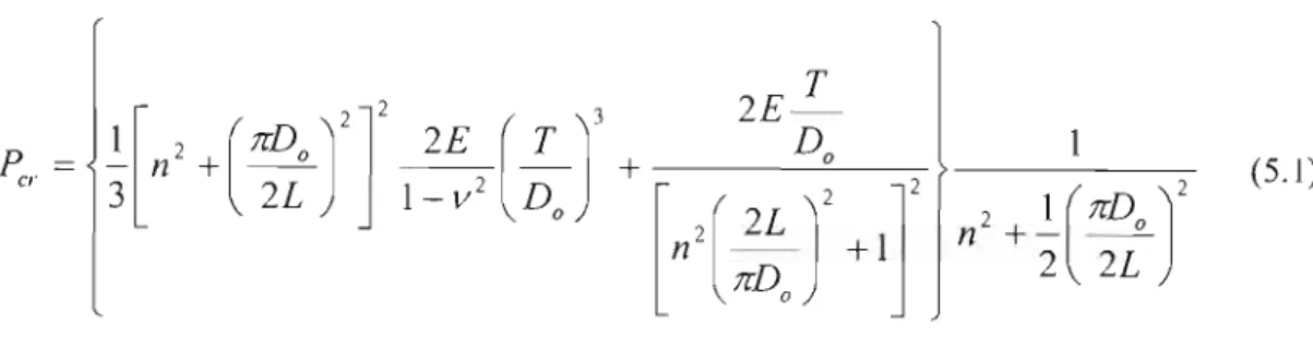
Experimental Model Basin, Windenburg, and Trilling [9] derived an approximate formula for Equation 5.1, independent of n, to determine the critical buckling pressure for a vessel under external axial and radial pressure. If the vessel length is greater than the critical length, the collapse pressure is given by Equation 5.2. For the design of pressure vessels under external pressure, the ASME VIII code developed a geometry chart and material table.
The thickness of the container can then be increased to raise the allowable pressure, ensuring that the applied load is lower and the container will not buckle under external pressure. The ASME code procedures for the design of pressure vessels under external pressure are also programmed into the CodeCalc software. The FEM model, Model B, for the analysis of the above vessel under external pressure is shown below.
Design of Pressure Vessels under External Pressure and Piping Loads
- Vessels with Geometric imperfections
- Numerical Results
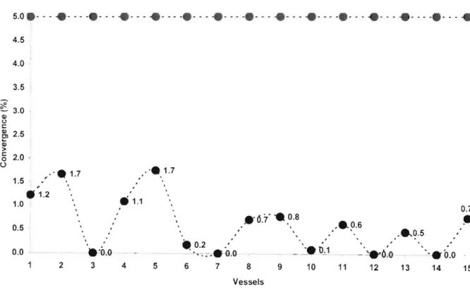
For the design of pressure vessels under the combined loading of external pressure and nozzle loads, the reduced critical buckling stress at the shell-to-nozzle connection must be calculated. Local stresses in this area should be within the reduced critical buckling stress to prevent failure of the vessel due to buckling. The results indicate that the reduction in the critical buckling pressure for vessels under external atmospheric pressure and nozzle tube loads can be achieved by using FEM.
The objective for the design of vessels under external pressure and nozzle loads will be to determine the reduced critical buckling stress and ensure that local stresses at the shell-to-nozzle junction are lower than the buckling stress. It has been shown that the reduction in the critical buckling stress can be determined by FEM methods. The reduced critical buckling pressure can be converted to a stress and should be compared to the more accurate FEM local stresses to determine if local buckling occurs at the cap-to-nozzle.
DISCUSSION
ASME Code uses two major graphs, Geometric and Material, to determine critical buckling pressure and stress. The ASME procedures calculate that the critical buckling stress or factor B is within the elastic range of the material. Second, the pipe loads at the nozzle cause deformations in the shell (Figure 5-25), reducing the critical buckling pressure.
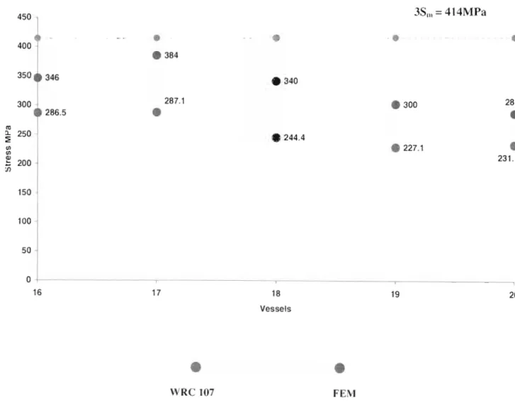
The local FEM stresses generated at the shell-to-nozzle junction were, for some vessels, much greater than the critical buckling stresses calculated using ASME Code procedures (Figure 5-21 and Figure 5-22). The FEM results showed a reduction in the critical buckling pressure as the pipe loads were increased. If local stresses are greater than the reduced critical buckling stress, the study showed that increasing the thickness of the shell will reduce the local stresses.
CONCLUSION
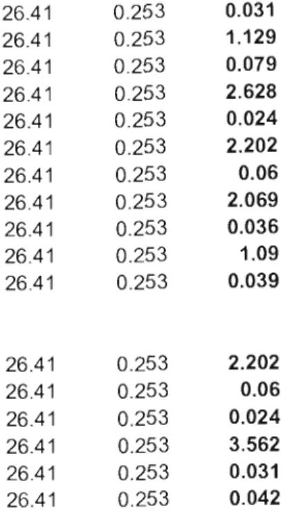
CRITERIA FOR DETERMINING DESIGN VALUE OF VOLTAGE INTENSITY FOR TABLES 2A AND 2B. Product/Material Tensile strength Yield strength Wrought or cast iron. LOADS AND MOMENTS OF HEAT EXCHANGER NOZZLES.. NOT USED AS CHASSIS FOR PIPINCI DESIGN) LOADS AND MOMENTS IF-Kill, M-KNM). Af'Pl"IEO'AT NOZZLE TO CYLINDER INTERSECTION). Tabulated loads and moments at the nozzle-cylinder intersection For high alloy heat exchangers (excluding alloy cladding) designed for temperatures between ·1 OO"'C and + 250cC the loads. Allowable pressure at corroded thickness Required pressure as entered by user Required thickness including corrosion everything. FEM buckling analyzes for vessel 6 and vessel 12 under external pressure and pipe loads for the six nozzles.
![Figure 2-6: Bending of thin plate. Reproduced from Benham and Crawford[31]](https://thumb-ap.123doks.com/thumbv2/pubpdfnet/10629871.0/24.828.203.635.110.524/figure-2-bending-plate-reproduced-benham-crawford-31.webp)
![Figure 3-2 : Stress-strain Diagram for typical structural steel under tension. Obtained from Gere and Timosbenko[33]](https://thumb-ap.123doks.com/thumbv2/pubpdfnet/10629871.0/51.828.228.690.616.968/figure-stress-diagram-typical-structural-tension-obtained-timosbenko.webp)
![Figure 4-1 : Buckling of an Idealized Structure. Obtained from Gere and Timosbenko[33]](https://thumb-ap.123doks.com/thumbv2/pubpdfnet/10629871.0/86.828.234.688.446.746/figure-buckling-idealized-structure-obtained-gere-timosbenko-33.webp)
