CONSTRUCTION OF A SMART HOME AUTOMATION SYSTEM WITH VOICE ACTIVATION AND FINGERPRINT SECURITY SYSTEM
By
Md. Amdadul Haq Arif Md. Abdul Hye Zebon Sheikh Monzur Elahi ID: 171-15-8648 ID: 171-15-8716 ID: 171-15-9027
This Report Presented in Partial Fulfillment of the Requirements for the Degree of Bachelor of Science in Computer Science and Engineering
Supervised By
Md. Sazzadur Ahamed
Senior Lecturer
Dept. of Computer Science and Engineering Daffodil International University
Co-Supervised By
Raja Tariqul Hasan Tusher
Senior Lecturer
Dept. of Computer Science and Engineering Daffodil International University
DAFFODIL INTERNATIONAL UNIVERSITY DHAKA, BANGLADESH
JUNE 2021
i | P a g e
©Daffodil International University
APPROVAL
This Project/internship titled “Construction of A Smart Home Automation System With Voice Activation And Fingerprint Security System”, submitted by Md. Abdul Hye Zebon, ID No: 171- 15-8716, Md. Amdadul Haq Arif, ID No: 171-15-8648 and Sheikh Monzur Elahi, ID No: 171-15- 9027 to the Department of Computer Science and Engineering, Daffodil International University has been accepted as satisfactory for the partial fulfillment of the requirements for the degree of B.Sc. in Computer Science and Engineering and approved as to its style and contents. The presentation has been held on 02 June, 2021.
BOARD OF EXAMINERS
________________________
Dr. Touhid Bhuiyan Professor and Head
Department of Computer Science and Engineering Faculty of Science & Information Technology Daffodil International University
Chairman
________________________
Subhenur Latif Assistant Professor
Department of Computer Science and Engineering Faculty of Science & Information Technology Daffodil International University
Internal Examiner
ii | P a g e
©Daffodil International University ________________________
Md. Abbas Ali Khan Senior Lecturer
Department of Computer Science and Engineering Faculty of Science & Information Technology Daffodil International University
Internal Examiner
________________________
Shah Md. Imran
Industry Promotion Expert
LICT Project, ICT Division, Bangladesh
External Examiner
iii | P a g e
©Daffodil International University
DECLARATION
We hereby declare that this project has been done by us under the supervision of Md. Sazzadur Ahamed, Senior Lecturer, Dept. of Computer Science and Engineering, Daffodil International University. We also declare that neither this project nor any part of this has been submitted elsewhere for award of any degree or diploma.
Supervised by:
_______________________
Md. Sazzadur Ahamed Senior Lecturer
Dept. of Computer Science and Engineering Daffodil International University
Co-Supervised by:
_______________________
Raja Tariqul Hasan Tusher Senior Lecturer
Dept. of Computer Science and Engineering Daffodil International University
Submitted by:
____________________ ___________________ ___________________
Md. Amdadul Haq Arif Md. Abdul Hye Zebon Sheikh Monzur Elahi
ID: 171-15-8648 ID: 171-15-8716 ID: 171-15-9027
iv | P a g e
©Daffodil International University
ACKNOWLEDGEMENT
First we express our heartiest thanks and gratefulness to almighty God for His divine blessing makes us possible to complete the final year project/internship successfully.
We really grateful and wish our profound our indebtedness to Md. Sazzadur Ahamed, Senior Lecturer, Department of CSE Daffodil International University, Dhaka. Deep Knowledge & keen interest of our supervisor in the field of “IOT” to carry out this project. His endless patience, scholarly guidance, continual encouragement, constant and energetic supervision, constructive criticism, valuable advice, reading many inferior draft and correcting them at all stage have made it possible to complete this project.
We would like to express our heartiest gratitude to our co-supervisor, Raja Tariqul Hasan Tusher, Senior Lecturer, Department of CSE and Dr. Touhid Bhuiyan, Professor and Head, Department of CSE, for his kind help to finish our project and also to other faculty member and the staff of CSE department of Daffodil International University.
We would like to thank our entire course mate in Daffodil International University, who took part in this discuss while completing the course work.
Finally, we must acknowledge with due respect the constant support and patients of our parents.
v | P a g e
©Daffodil International University
ABSTRACT
In this project, voice is used to operate switches. The reason for selecting speech is that it is readily replicated by humans. Furthermore, the use of expression provides an effective and simple control system. The implementation of this mechanism entails changing the switching system from the conventional method of physical interaction with the switch to a safer method in which voice replaces all physical contact. Home automation refers to building automation for a residence, also known as a smart home or smart house. Which includes the control and automation of lighting, heating, ventilation, air conditioning, and safety, as well as home appliances such as ovens and refrigerators/freezers. Bluetooth, WIFI, and GSM are only a few examples of wireless infrastructure. This paper introduces new designs and various home appliances. The ability to monitor the lamp using a mobile phone device with Bluetooth wireless technologies is the home automation application discussed in this article. The relays are used to link these appliances to the board's input/output ports. For this use, the architecture is low-cost, modular, and employs new technologies and devices. The use of a wireless Bluetooth connection in the control board enables a simpler interface implementation. Adding various sensors like gas sensor, temperature sensor, LDR and PIR sensor to the mix also made the whole system more unique and versatile. The system has been successfully built and operated.
vi | P a g e
©Daffodil International University
TABLE OF CONTENTS
CONTENTS PAGE
Board of examiners i
Declaration ii
Acknowledgements iii
Abstract iv
CHAPTER
Chapter 1 INTRODUCTION 1-2
1.1 Introduction 01
1.2 Aim of the project 01
1.3 Scopes 02
1.4 Methodology 02
1.5 Organization of the Report 02
Chapter 2 SYSTEM REVIEWS
03-05
2.1 Introduction 03
2.2 General Block Diagram 03
2.2.1 Block Diagram Description 04
2.3 Circuit Diagram 04
2.3.1 Working process of our Circuit 04
2.4 List of Component used in circuit 05
2.5 Conclusion 05
Chapter 3 COMPONENT DESCRIPTION 06-49
3.1 Introduction 06
3.2 Basic Description of Controller Unit 06
vii | P a g e
©Daffodil International University
3.2.1 Technical Specification Arduino MEGA 07
3.2.2 Description of Microcontroller ATmega2560 09
3.2.3 Block Diagram of Microcontroller – (ATmega2560) 10 3.2.4 Pin Configurations of Microcontroller – (ATmega2560) 11
3.2.5 Pin Description of Arduino MEGA 12
3.3 Description of Bluetooth Module (HC-05) 13
3.3.1 Features of Bluetooth Module (HC-05) 14
3.3.2 Pin Description of HC-05 15
3.3.3 Summary 15
3.4 Description of Adafruit Fingerprint Sensor Module (ADA751) 16 3.4.1 Features of Adafruit Fingerprint Sensor Module (ADA751) 16
3.4.2 Pin Description of ADA751 17
3.4.3 Summary 17
3.5 Description of Relay Module 18
3.5.1 Basic Working Procedure of Relays 19
3.5.2 Arduino Relay Module 20
3.5.3 Features of Arduino Relay Module 20
3.6 Description of LCD Display (20x4) 22
3.6.1 Shape and Sizes 23
3.6.2 Pin Description 24
3.6.3 Control Lines 25
3.6.4 Initialization and Instructions 26
3.7 Description of PIR Sensor Module (HC-SR501) 27
3.7.1 Features of PIR sensor (HC-SR501) 28
3.7.2 Pin Description of PIR Sensor (HC-SR501) 28
3.7.3 Motion Detection using PIR Sensor 29
3.7.4 Summery 29
3.8 Description of Gas Sensor Module (MQ-2) 30
3.8.1 Features of Gas Sensor Module (MQ2) 30
3.8.2 Pin Description of Gas Sensor Module (MQ-2) 31
3.8.3 Summary 31
3.9 Description of LDR Sensor Module 32
3.9.1 Features of LDR sensor Module 32
3.9.2 Pin Description of Gas Sensor Module (MQ-2) 33
3.9.3 Working Principle of LDR 34
3.9.4 Summary 34
3.10 Description of Temperature Sensor (LM35) 35
viii | P a g e
©Daffodil International University
3.10.1 Features of Temperature Sensor Module(LM35) 35
3.10.2 Pin Description of Gas Sensor Module (MQ-2) 36
3.10.3 Summary 36
3.11 Description of Servo Motor (SG90) 37
3.11.1 Features of Servo Motor (SG90) 38
3.11.2 Pin Description of Servo Motor (SG90) 38
3.12 Basic Arduino Software 39
3.12.1 Features of Arduino Software 40
3.13 Basic Description of Android Application 42
3.13.1 Arduino voice Application 43
3.14 Power supply 44
3.14.1 Resistance 45
3.15 Loads 47
3.16 Wires 48
3.17 Cost Analysis 49
3.17.1 Cost Sheet 49
3.18 Conclusion 49
Chapter 4 SOFTWARE ANALYSIS 50-53
4.1 Introduction 50
4.2 Description of the Arduino IDE 50
4.3 Flow Chart Diagram 52
4.4 Conclusion 53
Chapter 5: HARDWARE IMLEMENTATION 54-63
5.1 Introduction 54
5.2 Interfacing of Bluetooth Module(HC-05) 54
5.3 Interfacing with Application 55
5.4 Fingerprint Sensor Interfacing 56
5.5 Relay Module Interfacing 56
5.6 LCD Module Interfacing 57
5.7 PIR Sensor Module Interfacing 58
5.8 Gas Sensor Module Interfacing 59
5.9 LDR Sensor Module Interfacing 59
ix | P a g e
©Daffodil International University
5.10 Temperature Sensor Module Interfacing 60
5.11 Servo Motor Interfacing 61
5.12 Loads Interfacing 62
5.13 System Operation 63
5.14 Conclusion 63
Chapter 6: RESULTS AND DISCUSSION 64-73
6.1 Introduction 64
6.2 Experimental Setup 64
6.3 Result 67
6.4 Advantages 72
6.5 Disadvantages 73
6.6 Conclusion 73
Chapter 7: CONCLUSION 74-75
7.1 Conclusion 74
7.2 Application 74
7.3 Limitations of the works 75
7.4 Future Work 75
Appendix A 76
References 93
x | P a g e
©Daffodil International University
LIST OF FIGURES
FIGURES PAGE NO
2.1 General Block Diagram 3
2.2 Circuit Diagram 4
3.1.1(a) Arduino Mega 7
3.1.1(b) Arduino Mega 9
3.1.2 Block Diagram of Microcontroller (Atmega2560) 10
3.1.3 Pin Configuration of Microcontroller (ATmega2560) 11
3.2.1 Logo of Bluetooth 13
3.2.2 Bluetooth Module (HC-05) 14
3.2.3 Pins of HC-05 15
3.3.1 Adafruit Fingerprint Sensor (ADA751) 16
3.3.2 Pins of ADA751 17
3.4.1 Relay 18
3.4.2 Construction of relay 19
3.4.3 Arduino Relay Module 20
3.4.4 Pin configuration of relay module. 21
3.5.1 20X4 LCD Display Module 22
3.5.2 Diagram of the device 22
3.5.3 Address Location of 20x4 LCD 23
3.5.4 Different Models of LCD Display Module 23
3.5.5 Pin Diagram of LCD Display module 24
3.5.6 Flow Chart of Installation 26
3.6.1 PIR Sensor Module 27
3.6.2 Pins of HC-SR501 28
3.7.1 Gas Sensor Module (MQ-2) 30
3.7.2 Pins of Gas Sensor Module 31
3.8.1 LDR Sensor Module 32
3.8.2 Pins of LDR Sensor module 33
3.9.1 Temperature Sensor Module 35
3.9.2 Pins of Temperature Sensor Module 36
3.10.1 Servo Motor 37
3.10.2 Pins of Servo Motor 38
3.11 Arduino Software 39
3.12 Home page of the Android App 43
3.13.1 12v Power Supply 44
3.13.2 Resistance Color Code 46
3.14 Loads 47
3.15.1(a) Female to Male Jumper Wire 48
3.15.1(b) Male to Male jumper wire 48
3.15.2 220v Carrier Wire 48
4.1.1 Arduino Software Platform 50
4.1.2 Compiling window 51
4.2 Flow Chart Diagram 52
xi | P a g e
©Daffodil International University
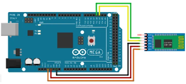
5.1 Bluetooth Module Interfacing 54
5.2(a) Interfacing with Application 55
5.2(b) Interfacing of Application 55
5.3 Fingerprint Sensor Interfacing 56
5.4 4-Channel Relay Interfacing 57
5.5 LCD Display Interfacing 57
5.6 PIR Sensor Module Interfacing 58
5.7 Gas Sensor Module Interfacing 59
5.8 LDR Sensor Module Interfacing 60
5.9 Temperature Sensor Module Interfacing 61
5.10 Servo Motor Interfacing 62
5.11 Interfacing with Loads 62
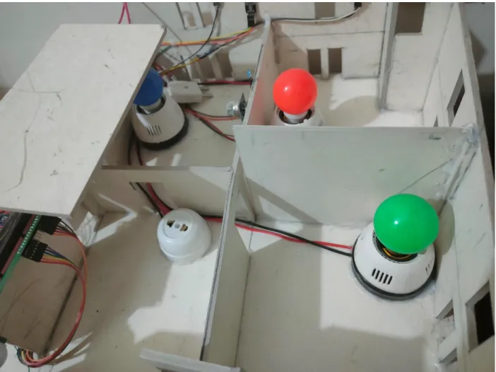
6.1.1(a) The Experimental Setup of the System 65
6.1.1(b) The Experimental Setup of the System 65
6.1.2 Working Condition of the System 66
6.2.1 Welcome Message shown through the LCD display 67
6.2.2 Opening the door when match found 67
6.2.3 Showing message when no match found 68
6.2.4(a) Giving voice command and showing output 68
6.2.4(b) Giving voice command and showing output 69
6.2.5 Controlling the loads with LDR sensor 69
6.2.6 Controlling the loads with PIR sensor 70
6.2.7 Controlling the loads with both PIR sensor and LDR Sensor 70 6.2.8 LCD display showing the temperature and gas data of the
environment 71
6.2.9 Turning on notification LED finding excessive temperature 71 6.2.10 Turning on notification LED finding excessive burnable gas 72
xii | P a g e
©Daffodil International University
LIST OF TABLES
TABLES Page NO
2.1 list of component we used 6 5
3.1 Technical specification of Arduino UNO 10 8
3.2 Pins Description of Bluetooth Module 15
3.3 Pin Description of Adafruit Fingerprint Sensor Module 17
3.4 Pin Description of LCD 24
3.5 Pin Description of PIR Sensor Module 28
3.6 Pin Description of Gas Sensor Module 31
3.7 Pin Description of LDR Module 33
3.8 Pin Description of Temperature Sensor Module 36
3.9 Pin Description of Servo Motor 38
3.10 Cost Sheet 49
1 | P a g e
©Daffodil International University
CHAPTER 1 Introduction
1.1 Introduction
Home automation is the control of home appliances such as doors, fans, televisions, air conditioners, and other household features through local networking or remotely. It also provides some degree of residential security and is also equipped with various emergency systems. It gives the user power over his house's appliances and protection system. For example, if the consumer uses the smartphone to control the home appliances of the house, it reduces the several manual actions that might have been needed before. Which is both time saving and energy saving at the same time. In this paper, we are presenting a very promising design of a “Fingerprint Based Smart Home Automation”. In this project, we used an Arduino MEGA Microcontroller to control several home appliances represented as bulbs and a whole bunch of sensors to ensure the security of the whole system, while making the control of the system wireless using Bluetooth wireless technology.
1.2 Aim of the Project
1. Designing a home automation system by controlling the home appliances.
2. Designing a proper security system along with home automation.
3. Making the whole system "Smart" by using Bluetooth technology.
4. Pairing an Android application with the system.
5. Designing a working circuit design for the system 6. Implementing the system in real life.
2 | P a g e
©Daffodil International University
1.3 Scopes
1. A low-cost home automation system that can make daily life works easy in millions of houses.
2. It can be mass-produced commercially in industries.
3. It comes with an open-source android application to pair with and use frequently.
4. It can work automatically without human intervention using various sensors.
5. It also offers a fingerprint-based security system.
1.4 Methodology
The Smart Home Automation System that we designed in this project is used to control all the appliances that are connected to the microcontroller. The methodology of the proposed system is mainly divided into four steps. In the initial step, the fingerprint sensor works as the security system for the whole automation system. After that, an Android application interacts with the Bluetooth module of the system. Users can decide to use the installed sensors to control the various devices.
Then in the next step, the microcontroller receives the signal which is sent by either the Bluetooth module or the sensors installed around the rooms. Then microcontroller sends the activation signal to the relay module. Finally, in the last step, the relay module switches the devices that are connected to the relay.
1.5 Organization of the report
This project summary is divided into seven chapters. The first chapter presents an idea for our project "Fingerprint Based Smart Home Automation System," as well as a short overview of the project's scopes and methods. The second chapter covers history, block diagrams, circuit diagrams, and part lists. Chapter three is about feature classification, cost analysis of our system. The fourth chapter examines tech and explains how it works. The hardware implementation is covered in Chapter 5. The sixth chapter then properly explains the outcome and dialogue. Finally, chapter seven provides closing comments, limitations of our method, and potential job suggestions.
3 | P a g e
©Daffodil International University
CHAPTER 2 System Reviews 2.1 Introduction
The smart home automation system allows people to control various home appliances by using a user-friendly android application or by using various pre-installed sensors around the house. For designing a home automation system, it is important to focus on hardware and use good phone applications. It is also important not to forget about the security part of the system. This product can deal with various home appliances such as lights, fans, AC, TV, etc. Furthermore, the device contains a slew of sensors, such as a temperature sensor and a gas sensor, to alert the consumer of a possible threat. In this chapter, we will discuss about the block diagram, the circuit diagram and the list of components used in this project.
2.2 General Block Diagram
Fig 2.1: General Block Diagram
4 | P a g e
©Daffodil International University
2.2.1 Block Diagram Description
As seen in the block diagram of the home automation system in fig.2.1, using the Arduino MEGA, we can operate the Fingerprint sensor, Bluetooth module, relay module, and other complementary sensors. When the fingerprint sensor reads data, it transmits the signal to the control module (Arduino MEGA), which starts the protection protocol. When the dedicated command is available, then the Bluetooth module (HC-05) sends a digital output to the control unit. On the other hand, if the user wants to use a sensor rather than passing commands through the smartphone app, the sensors will transmit data to the control module. After analyzing the data, the control units will send commands to the relay module to switch ON/OFF.
2.3 Circuit Diagram
Fig 2.2: Circuit Diagram
2.3.1 Working Process of our Circuit
The Fingerprint based Smart Home Automation project comes with an open source android application called “AMR_Voice”. The various appliances connected to our Arduino Mega and relays are controlled by this application. Bluetooth signals are sent from our Android phone to the Bluetooth module we've wired to our Arduino as we press the application's toggle keys. The Arduino determines which signals were sent by comparing it to the predetermined signals assigned to each equipment. When the Arduino senses the signal, it switches on the relay connected to its digital pin by sending 5V through it. As a result, the relay is activated, and the accompanying appliance connected to the relay is activated as well. The same thing happens if we use sensors
5 | P a g e
©Daffodil International University
instead of the app. When the sensors are triggered, it sends data to the Arduino. Then the Arduino analyses the data and passes the signal to the relay accordingly. To switch off the relays, Arduino passes a 0V or logic low to the corresponding digital pins.
2.4 List of Components used in Circuit
TABLE 2.1: LIST OF COMPONENT WE USED
No Component Name Quantity Used
01 Microcontroller- ATmega2560 (Arduino Mega)
01 To Control the System.
02 Bluetooth Module (HC-05) 01 To direct communication.
03 Adafruit Fingerprint Sensor (ADA751) 01 For security.
04 Relay Module 01 To switching.
05 20x4 LCD Display Module 01 Showing Text.
06 PIR Sensor Module(HC-SR501) 01 To detect motion.
07 Gas Sensor Module (MQ-2) 01 To measure the gas level.
08 Light Sensor Module (LDR) 01 To measure the brightness.
09 Temperature Sensor Module (LM35) 01 To measure temperature.
10 Servo Motor (SG90) 01 To open the door.
11 Arduino Software To compile code.
12 Arduino Voice Control App 01 To giving command.
13 Ac to dc power supply 02 Power Supply.
14 Load 04 Showing Output.
15 Wire To connect the components
2.5 Conclusion
Because of its attractive properties, the home automation system is used in many applications such as houses, hostels, offices, and automobiles.
6 | P a g e
©Daffodil International University
CHAPTER 3 Component Description
3.1 Introduction
The system hardware is made up of an Arduino Mega, a 4-channel relay module, a Bluetooth module (HC-05), a fingerprint sensor, a temperature sensor module, a light sensor module, a gas sensor module, a motion detector module, an LCD display module, a power supply, several cables, an Arduino compiler, and Android application. In this chapter we will discuss about component description, features, working procedure and cost analysis of our whole system.
3.2 Basic Description of Controller Unit
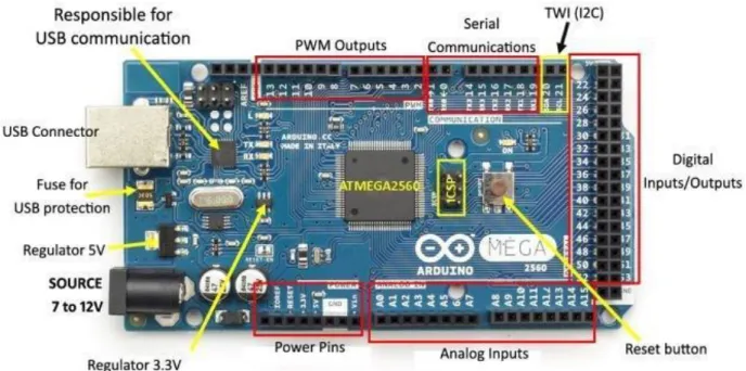
The Arduino hardware board is used in the controller unit (with AVR microcontroller). With the assistance of the Arduino1.6.8 software platform, we can conveniently program AVR ICs to meet our needs. Arduino is an open and free electronic application framework that is built on adaptable, user-friendly hardware and software. It's aimed at designers, programmers, enthusiasts, and everyone else interested in making immersive objects or environments. To program the board's microcontroller, the Arduino programming language (based on Wiring) and the Arduino development environment are used (based on Processing). The ATmega2560-based Arduino Mega is a microcontroller module. It has 54 optical I/O pins (of which 15 are PWM outputs), 16 analog inputs, 4 UARTs (hardware serial ports), a 16 MHz crystal oscillator, a USB link, a power jack, an ICSP header, and a reset button. It includes everything you need to assist the microcontroller;
simply connect it to a device through USB or power it with an AC-to-DC adapter or battery to get started. The Arduino Mega 2560 is an improvement on the Mega that it replaces. [1]
7 | P a g e
©Daffodil International University
3.2.1 Technical Specification Arduino MEGA
Fig 3.1.1(a): Arduino Mega
8 | P a g e
©Daffodil International University
TABLE 3.1: TECHNICAL SPECIFICATION OF ARDUINO UNO
Microcontroller ATmega2560
Operating Voltage 5V
Supply Voltage (recommended) 7-12V Maximum supply voltage (not
recommended)
20V
Digital I/O Pins 54 (of which 15 provide PWM output)
Analog Input Pins 16
DC Current per I/O Pin 20 Ma
DC Current for 3.3V Pin 50 mA
Flash Memory 32 KB (ATmega2560) of which 0.5 KB
used by boot loader
SRAM 2 KB (ATmega2560)
EEPROM 4 KB
Clock Speed 16 MHz
LED_BUILTIN 13
Length 101.52 mm
Width 53.3 mm
Weight 37 g
9 | P a g e
©Daffodil International University
3.2.2 Description of Microcontroller ATmega2560
Fig 3.1.1(b): Arduino Mega
The ATmega2560 microcontroller is found in boards including the "Arduino Mega." It has 54 optical I/O pins, 16 of which are analog inputs and 14 of those are PWM outputs, 4 hardware serial ports (UARTs), a crystal oscillator-16 MHz, a USB connector, an ICSP header, a power socket and a RST button. This board mainly includes all of the components used to support the microcontroller. Because of that, powering this board is as simple as connecting it to a computer with a USB cable, a battery, or an ac to dc converter. To protect this board from an unintended electrical discharge, a base plate should be used. The SCL and SDA pins on the Mega 2560 R3 board are connected to the AREF pin. Furthermore, there are two most recent pins next to the RST pin. The IOREF is a single pin on the Arduino board that allows shields to adjust the voltage provided by the board. Another pin is left unconnected and can be included in the future. These boards are designed to work with any current shield, but they can be modified to work with newer shields that use these extra pins.[9]
10 | P a g e
©Daffodil International University
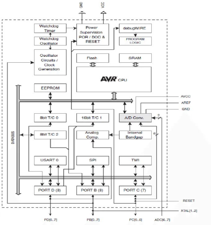
3.2.3 Block Diagram of Microcontroller – (ATmega2560)
Fig 3.1.2: Block Diagram of Microcontroller (Atmega2560)
11 | P a g e
©Daffodil International University
3.2.4 Pin Configurations of Microcontroller – (ATmega2560)
Fig 3.1.3: Pin Configuration of Microcontroller (ATmega2560)
12 | P a g e
©Daffodil International University
3.2.5 Pin Description of Arduino MEGA
● VIN: When the Arduino board is driven by an external source, this voltage is applied to it (as opposed to 5 volts from the USB connection or other regulated power source). This pin may be used to supply voltage or to access voltage if it is supplied by the power socket.
● 5V: The power supply that is controlled and powers the microcontroller and other board parts. This can be supplied by VIN via an on-board regulator, USB, or another 5V operated supply.
● 3.3V: The on-board regulator produces 3.3 volts. The maximum current consumption is 50 mill amperes (mA).
● GND: Ground pin.
● Serial Serial number 1: 19 (RX) and 18 (TX); Serial number 2: 17 (RX) and 16 (TX);
Serial number 3: 15 (RX) and 14 (TX) (TX). This computer receives (RX) and transmits (TX) TTL serial data. Pins 0 and 1 are all connected to the matching pins on the ATmega16U2 USB-to-TTL Serial chip.
● External Interrupts:2 (interrupt 0), 3 (interrupt 1), 18, 5 (interrupt 4), 20 (interrupt 3) and 21 (interrupt 3). (interrupt 2). These pins may be configured to generate an interrupt on a low value, a rising or falling edge, or a value change. See the attachInterrupt() feature for more details.
● PWM: From 0 to 13 pin. The analogWrite() function generates 8-bit PWM output.
● SPI: 52 (SCK), 53 (MISO), 51 (MOSI), 52 (MOSI), 51 (MISO), 51 (MOSI), 51 (MISO), 51 (MIS (SS). The SPI library is used to communicate with these pins using SPI. On the ICSP header, which is mechanically compatible with the Arduino Uno, Diecimila and Duemilanove, the SPI pins are also isolated.
● LED: A built-in LED is connected to optical pin 13. 13. The LED is turned on when the pin is high; when the pin is low, the LED is turned off.
● TWI: 21 (SDA) and 20 (SDA) (SCL). Using the Wire library, you can support TWI contact. These pins are not in the same place as the Duemilanove or Diecimila's TWI pins.
● AREF: The analog inputs' reference voltage. Used in conjunction with analogReference().
● Reset: To reset the microcontroller, connect this line to ground. A reset button is frequently used to refer to shields that block the board’s. [1][9]
13 | P a g e
©Daffodil International University
3.3 Description of Bluetooth Module (HC-05)
We live in a society where “wireless” has become the new normal. From phones to gaming consoles, everything is wireless! Wireless technology has allowed us to use mobile devices with an unlimited flexibility that was historically unavailable due to the existence of hideous cables attached to our devices. There are several types of wireless connectivity, including such Wi-Fi, cellular data, and Zigbee, and yet Bluetooth is one of the most successful and often used wireless systems. Although the Bluetooth 5.2 standard was released in 2020, we'll be using the Bluetooth 4.2 standard since it's the most widely available at the moment.
Fig 3.2.1: Logo of Bluetooth
The HC-05 module is a simple Bluetooth SPP (Serial Port Protocol) module intended for setting up a transparent wireless serial connection. The Bluetooth module is a perfect solution for wireless networking because It is capable of being used in a Master/Slave configuration.This Bluetooth V2.0+EDR (Enhanced Data Rate) 3Mbps Modulation serial port Bluetooth module comes complete with a 2.4GHz antenna transceiver and baseband. CSR Blue-core 04External single chip Bluetooth device with CMOS technology and AFH (Adaptive Frequency Hopping Feature). is included. The HC-05 Bluetooth module is a MASTER/SLAVE module. The configuration is SLAVE by default. AT COMMANDS are the only way to customize the module's Role (Master or Slave). The slave modules isn’t allowed to activate a connection to another Bluetooth device, but they do accept other connections from other Bluetooth devices. The master module has the ability to initiate a connection to other devices. [17]
14 | P a g e
©Daffodil International University
Fig 3.2.2: Bluetooth Module (HC-05)
3.3.1 Features of Bluetooth Module (HC-05)
Hardware Features• Sensitivity is usually 80dBm.
• RF transfer power of up to +4dBm
• I/O voltages ranging from 3.3 - 5 V.
• PIO (Programmable Input/Output) control.
• A changable baud rate including UART interface.
• Has an embedded antenna.
• Comes with an edge connector.
Software Features
• Slave mode by default, baud rate 9600 with stop bit = 1 and data bits = 8 and no parity.
• Auto‐connects to the last device on power by default.
• allow pairing device to connect by default.
• Uses PINCODE ”1234” for pairing automatically. [17]
15 | P a g e
©Daffodil International University
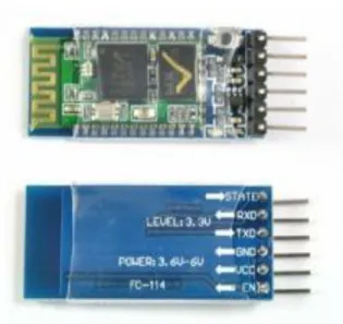
3.3.2 Pin Description of HC-05
Fig 3.2.3: Pins of HC-05
TABLE 3.2: PINS DESCRIPTION OF BLUETOOTH MODULE
Sl. Pin Name Description
1. +5V or 3.3V This pin is used as 5V supply or Power Pin.
2. TX This pin is used to send the data/command to be sent.
3. RX This pin is used to read received results.
4. KEY/EN Input pin that switches the module between the Data and AT Command modes.
5. STATE It is an Output pin, the module's state is shown by this pin.
6. GROUND 0V / GND
3.3.3 Summary
Finally, this is an excellent device for use at home or in the workplace. Since this is a low-risk initiative, it is both cost effective and successful. It outperforms most wireless communication methods in terms of short-term communication.
16 | P a g e
©Daffodil International University
3.4 Description of Adafruit Fingerprint Sensor Module (ADA751)
Biometrics-based security is the most authentic security nowadays. There are so many types of Biometrics based security systems around us, such as Face Recognition, Iris Scanning, Fingerprint Recognition, etc. Fingerprint sensors, such as the one seen in the fig below, have made fingerprint recognition quite available and simple to incorporate into any Arduino-based projects. This implies that fingerprint processing, registration, comparison, and search are all extremely simple. These modules provide FLASH memory for storing fingerprints and can be used with any microcontroller or device that supports TTL serial. These modules are capable to be applied to surveillance systems, automatic door locks, attendance systems, and a variety of other applications.[17]
Fig 3.3.1: Adafruit Fingerprint Sensor (ADA751)
3.4.1 Features of Adafruit Fingerprint Sensor Module (ADA751)
• Voltage supply is DC 3.6 to 6.0V
• Current supply is less than 120mA
• Backlight color is blue
• Interface is UART
• Bad rate is 9600
• Safety level is five (from low to high: 1,2,3,4,5)
• False Accept Rate (FAR) is less than 0.001% (security level 3)
• False Reject Rate (FRR) is less than 1.0% (security level 3)
• It is capable of storing 127 different fingerprints
17 | P a g e
©Daffodil International University
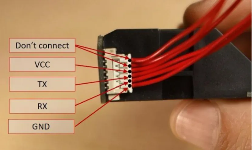
3.4.2 Pin Description of ADA751
Fig 3.3.2: Pins of ADA751
Table 3.3: Pin Description of Adafruit Fingerprint Sensor Module
Sl. Pin Name Description
1. VCC +5V supply or Power Pin.
2. TX The Data/Command to be transmitted is sent using this pin.
3. RX The Received data is read using this pin.
4. GND 0V / GND or Power Pin
3.4.3 Summary
If you don't put your finger exactly as you did before you saved it, the sensor can have difficulty recognizing it. We've learned that placing your finger carefully on the scanner improves the sensor's efficiency. The fingerprint sensor module, in our view, works very well and is a cost- effective way to incorporate biometric authentication to any entry level projects.
18 | P a g e
©Daffodil International University
3.5 Description of Relay Module
A relay is a switch that uses electromagnetic signals that, when activated or deactivated by a tiny electric current, activates or disconnects a much larger current. An electromagnet is a coil of wire which then becomes a short-lived magnet as electricity passes through it, is at the heart of a relay.
It is like an electrical toggle, we should think of a relay, switching it on with some little current and switching on another one with as much greater current ("leverages"). How effective is this?
As the name suggests, many sensors unite incredibly delicate equipment pieces and only produce small electric currents. However, we normally use them to drive bigger devices using greater currents. Relays cross the void, allowing small currents to enable bigger ones. As a result, relays will either function like switches, switching things on and off, or as transducers, converting small currents into larger ones. [11]
Fig 3.4.1: Relay
19 | P a g e
©Daffodil International University
3.5.1 Basic Working Procedure of Relays
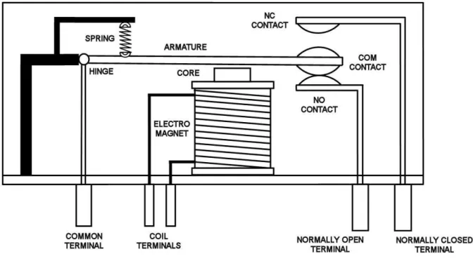
Fig 3.4.2: Construction of relay
The illustration depicts an inner part schematic of a relay. An iron core is surrounded by a power coil. As seen, the power supply is supplied to the electromagnet through a control switch and contacts to the load. As electricity flows through the center coil, the electromagnet becomes energized, intensifying the magnetic field. As a result, the higher touch arm becomes attracted to the lower fixed arm, closing the contacts and creating a short circuit for the load. If the relay was still not energized before the connections were closed, the contacts would pass in the opposite direction and form a circle. When the coil electricity is turned off, the movable core can be pushed back to its original location by a force. This force would be about 0.5 the power of the gravitational force. This force is primarily supplied by two causes, one being the spring and the other being the gravity at the same time. Relays are mostly designed for two simple functions. The first is for medium voltage applications, and the second is for high voltage applications. Additional consideration would be extended to reducing the noise of the entire circuit in low voltage applications. For high-voltage systems, they're mostly intended to reduce the phenomena known as arcing. [11]
20 | P a g e
©Daffodil International University
3.5.2 Arduino Relay Module
Fig 3.4.3: Arduino Relay Module
The relay is a battery-powered switch that allows you to turn on or off a connection with much high current and/or voltage than a microcontroller would handle. The microcontroller-controlled low voltage circuit and the high power circuit have no relationship. The relay isolates each circuit from the others. Each channel in the module has three links called NC, COM, and NO.
The jumper cap would be set to high level effective mode, which ‘closes' the normally open (NO) switch at high level input, or low level effective mode, which behaves the same as high level input but at low level input. [11]
3.5.3 Features of Arduino Relay Module
● On-board EL817 photon emission coupler with anti-interference photonic isolating capability; efficient on-board 5V, 10A / 250VAC, and 10A / 30VDC relays.
● The long-lasting relay will consume 100000 times in a row.
● With the output signal indicator, the module is allowed to be directly and MCU I/O connected.
● Diode current safety module with quick reaction period.
● PCB Dimensions is 45.8mm x 32.4mm
21 | P a g e
©Daffodil International University
Fig 3.4.4: Pin configuration of relay module
1. VCC 5V DC
2. IN4 high/low output 3. IN3 high/low output 4. IN2 high/low output 5. IN1 high/low output 6. GND ground
22 | P a g e
©Daffodil International University
3.6 Description of LCD Display (20x4)
A liquid crystal display (LCD) is a thin, flat display device made up of an arrangement of color or monochrome pixels arranged in front of a light source or reflector. A column of liquid crystal molecules is sandwiched between two transparent electrodes and two polarizing filters with perpendicular polarity axes to form each pixel. The LCD display is not permitted, the data lines are tri-state, and they do not interfere with the operation of the microcontroller. Data can be shown on the LCD in any orientation.
Fig 3.5.1: 20X4 LCD Display Module
For 20×4 LCD, the address locations are given below.
Fig 3.5.2: Diagram of the device
23 | P a g e
©Daffodil International University
Fig 3.5.3: Address Location of 20x4 LCD
3.6.1 Shape and Sizes
Despite being limited to character-based units, there is a wide variety of shapes and sizes available.
Line lengths of 8, 16, 20, 24, 32, and 40 characters are standard, with one, two, and four line versions available.
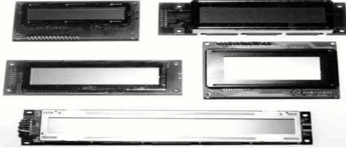
Fig 3.5.4: Different Models of LCD Display Module
There are many different LC innovations. “Supertwist” varieties, for example, outperform older
“twisted nematic” types in terms of contrast and viewing angle. Any modules have back lighting, allowing them to be seen in low-light environments. The back lighting can be either “electro- luminescent,” which necessitates a plain LED illumination. [12]
24 | P a g e
©Daffodil International University
3.6.2 Pin Description
The majority of LCDs with a single controller unit have 14 pins, while LCDs with two controllers have 16 pins, plus two extra pins for back-light LED connections.
Fig 3.5.5: Pin Diagram of LCD Display module
TABLE 3.4: PIN DESCRIPTION OF LCD
25 | P a g e
©Daffodil International University
3.6.3 Control Lines
The EN Line is called "Enable." This control line alerts the LCD that data is being sent to it. Until setting the other two control lines and/or placing data on the data bus and transferring data to the LCD, make sure this line is low (0). When all of the other lines are over, hold EN high (1) for the minimum amount of time given by the LCD datasheet (which varies by LCD), then return it to low (0).
The abbreviation RS Line refers to the "Register Choose" line. When RS is zero, the data is regarded as an order or special instruction (such as clear screen, position cursor, etc.). When the RS parameter is set to one (1), the data sent is text data that should be mirrored on the screen. Set RS high to display the letter "T" on the computer, for example.
RW Line denotes the "Read/Write" control line. Since RW is set to zero, data from the data bus is written to the LCD. The program is querying (or reading) the LCD since RW is set to one (1).
There is only one possible read order ("Get LCD status"). RW will almost always be small and all of the others are write instructions. Finally, the data bus has four to eight lines (depending on the mode of operation selected by the user). An 8-bit data bus's lines are denoted as DB0, DB1, DB2, DB3, DB4, DB5, DB6, and DB7. [12]
26 | P a g e
©Daffodil International University
3.6.4. Initialization and Instructions
If the voltage requirements for the internal reset circuit's routine operation are not met, a series of instructions must be performed to initialize the LCD unit. The procedure for this initialization step is as follows, as shown above.
Fig 3.5.6: Flow Chart of Installation
27 | P a g e
©Daffodil International University
3.7 Description of PIR Sensor Module (HC-SR501)
A PIR sensor senses a person traveling within roughly 10m of the sensor. The real detection range is between 5m and 12m, so this is an average value. PIRs are essentially composed of a pyroelectric receptor capable of detecting quantities of infrared radiation. For a variety of sensitive projects or items including learning whether a person has departed or arrived on the scene. PIR sensors are fantastic; they have flat power with little effort, a wide lens range, and are simple to use. The bulk of PIR sensors are equipped with a three-pin connector on the side or bottom. One pin will serve as ground, another as a signal, and the last as a power. Control is usually limited to 5V. Larger modules cannot provide direct output and would instead use a relay, in which case there are associations with ground, power, and two switches. The PIR sensor to a microcontroller is very easy to mount. Since the PIR acts as a digital output, wait until the pin is high or low. A high signal can be used to feel motion on a single I/O pin. After the sensor has warmed up, the output remains small before operation, then swings high a few seconds until it returns low. If the movement happens, the output will cycle until the line of sight of the sensor remains steady. In order to work well, the PIR sensor is warmed up to a specific end goal. This is because of the settling time required for studying the realm of nature. It could be 10 to 60 seconds anywhere. During the period, as little motion should be expected in the field of view of the sensor. [13]
Fig 3.6.1: PIR Sensor Module
28 | P a g e
©Daffodil International University
3.7.1 Features of PIR sensor (HC-SR501)
Full PIR, movement detection.
Low Noise and High Sensitivity Dual Element Sensor.
Voltage of supply – 5V.
Adjustable delay time.
TTL Output Norm.
3.7.2 Pin Description of PIR Sensor (HC-SR501)
Fig 3.6.2: Pins of HC-SR501
Table 3.5: Pin Description of PIR Sensor Module
Sl Pin Name Description
1 Vcc For standard implementations, the input voltage is +5V. Can be between 4.5V and 12V
2 High/Low Ouput (Dout)
When activated, high digital pulse (3.3V) (motion detected) Low(0V) digital when idle(no motion is found)
3 Ground Connected to ground of circuit
29 | P a g e
©Daffodil International University
3.7.3 Motion Detection using PIR Sensor
The activity of people in the area is sensitive to a PIR or Passive Infrared Sensor. Leistung may be used to track the movement of the door. When a beam is emitted by another part of the device, a light sensor is used in motion detection to sensitivity of the presence of infrared light produced by a warm target, or the failure of infraround light. A PIR camera detects the infrarot light produced by a warm target. It consists of pyroelectric sensors that transform changes in temperature into an electrical signal (due to incident infrarot radiation). When infrarot light strikes a crystal, an electric charge is produced. The location of people within a 14-meter detection range can also be detected by a PIR sensor.
3.7.4 Summary
The HC-SR501, like most PIR sensors, takes some time to acclimate to the infrared energy in the room. When the sensor is first turned on, this will take anywhere from 30 to 60 seconds. In addition, after taking a reading, the sensor has a "reset" time of around 5 or 6 seconds. It will not sense any motion during this period. These delay times must be considered when implementing a device based on the HC-SR501.
30 | P a g e
©Daffodil International University
3.8 Description of Gas Sensor Module (MQ-2)
The sensors of MQ-2 are used for the detection and quantification of LPG, alcohol, propane, hydrogen, carbon monoxide and methane. A digital pin has been installed on the module version of this sensor to enable it to operate with no microcontroller which only serves to detect a single gas. The analog pin must be used for measuring the gas in ppm. The analog pin is also TTL-based and is 5V-based, which means even the latest microcontrollers will run it. The detection of a gas with a MQ sensor is very simple. The optical or analog pins may be used for this. Just attach the module to 5V and on the module glow you can see the control LED. The output LED will remain turned off when no gas is detected, meaning that the optical output pin is 0V. Remember that for a preheating time (as described in the above section of functions) these sensors have to be activated before using them. Insert the sensor into the gas to be detect and the output LED and digital pin can be seen to increase; otherwise the potentiometer should be set until the output rises. [15]
Fig 3.7.1: Gas Sensor Module (MQ-2)
3.8.1 Features of Gas Sensor Module (MQ2)
● +5V is the operating voltage.
● This instrument can test or track LPG, alcohol, propane, hydrogen, CO and even methane.
● 0V to 5V analog output voltage
● 0V or 5V digital output voltage
● Preheat time is 20 seconds
● It can be used both as a digital and an analog sensor.
● The potentiometer can be used to adjust the sensitivity of the digital pin.
31 | P a g e
©Daffodil International University
3.8.2 Pin Description of Gas Sensor Module (MQ-2)
Fig 3.7.2: Pins of Gas Sensor Module
TABLE 3.6: PIN DESCRIPTION OF GAS SENSOR MODULE
Sl Pin Name Description
1 Vcc This pin enables the module, usually +5V voltage 2 Ground To attach the module to the ground of the device 3 Digital
Out
You can also use this sensor to obtain digital output from that pin by using the potentiometer to set a threshold value
4 Analog Out
The analog voltage of this pin is 0-5V dependent on gas pressure
3.8.3 Summary
Gases including LPG, alcohol, propane, hydrogen, carbon, mono-carbon and methane are detectable and quantified by the MQ-2 gas sensor. A digital pin has been installed on the module version of this sensor to enable it to operate with no microcontroller which only serves to detect a single gas. This sensor might also be a great match if you are trying to detect or measure a sensor with or without microcontrollers for gasses such as LPG, alcohol, propane, hydrogen and CO.
32 | P a g e
©Daffodil International University
3.9 Description of LDR Sensor Module
In certain cases, the majority of street lamps, exterior lights, and a variety of home devices are powered and controlled manually. It is not only dangerous, but also wastes electricity due to staff incompetence or unusual conditions in turning this electrical equipment on and off. As a result, by utilizing a light sensor, we will use the light sensor circuit to automatically turn OFF the loads depending on the intensity of daylightThis article briefly outlines what a light dependent resistor is, how to build and how to apply a light dependent resistance circuit. A light-based resistor is a type of resistor that reacts to light, also known as a photo-resistor, photocell or photocell. It is a resistor that varies with the amount of light on the board. The resistance grows as light reflects on the resistor. These resistors are also found in many circuits with anticipated light presence. These resistors are resistant to a wide variety of roles. The LDR is in the dark and can be used to turn off the light, for example, when it is in the light. A standard light resistor has 1MOhm resistance in the dark and a few Kilo Ohms resistance in the light. [18]
Fig 3.8.1: LDR Sensor Module
3.9.1 Features of LDR sensor Module
● It is possible to use it to detect light.
● Simple to use on a breadboard or a perf board
● Simple to use with microcontrollers or even standard digital/analog ICs
● Small, inexpensive, and widely accessible
● Available in the PG5 and PG5-MP series, as well as the PG12 and PG12-MP series, as well as the PG20 and PG20-MP series.
33 | P a g e
©Daffodil International University
3.9.2 Pin Description of Gas Sensor Module (MQ-2)
Fig 3.8.2: Pins of LDR Sensor module
TABLE 3.7: PIN DESCRIPTION OF LDR MODULE
Sl Pin Name Description
1 VCC This pin enables the module, usually +5V voltage 2 GND To attach the module to the ground of the device 3 DO Digital Output Pin
4 AO Analog Output Pin
34 | P a g e
©Daffodil International University
3.9.3 Working Principle of LDR
It works according to the theorem of photo conductance. It is just that as light reaches the surface, the conductivity of the substrate decreases and electrons are moved into the conducting band by the unit. These light photons will be more energy-efficient than the gap in band of the semiconductor material. It transfers electrons from the valence band to the driving band.
3.9.4 Summery
LDR sensor module is a low-cost optical and analog sensor module that can monitor and sense light intensity. This sensor is often referred to as a photoresistor sensor. This sensor has an onboard LDR (Light Dependent Resistor) that aids in the detection of light. This sensor module has four terminals. Where the "DO" pin represents a digital output pin and the "AO" pin represents an analog output pin. In the absence of light, the module's performance is high and in the presence of light, it is low. The sensor's sensitivity can be changed using the onboard potentiometer.
35 | P a g e
©Daffodil International University
3.10 Description of Temperature Sensor (LM35)
The most often calculated environmental quantity is temperature. This is understandable given that temperature affects the majority of human, electrical, chemical, mechanical, and biological processes. In small temperature ranges, certain chemical reactions, biological processes and even electronic circuits perform well. Temperature is one of the most often measured variables so the existence of multiple detection methods is not surprising. Without actual interaction with the source, radiated irradiation may be used for temperature sensing or indirectly with the heating source. The many temperatures senses available today are the thermocouples, resistance temperature detectors (RTD), infrareds, and semiconductors. [14]
Fig 3.9.1: Temperature Sensor Module
3.10.1 Features of Temperature Sensor Module(LM35)
● The module is calibrated in Celsius Centigrade
● Rated for a temperature range of l 55 to +150 C.
● Appropriate for remote applications
● Because of its wafer-level trimming, the module is cost efficient.
● Voltage ranges from 4 - 30 volts.
● Low self-heating, standard nonlinearity of one-fourth of C
36 | P a g e
©Daffodil International University
3.10.2 Pin Description of Gas Sensor Module (MQ-2)
Fig 3.9.2: Pins of Temperature Sensor Module
TABLE 3.8: PIN DESCRIPTION OF TEMPERATURE SENSOR MODULE
Sl Pin Name
Description
1 + Typical applications input voltage of +5V
2 S Increase of 10mV can be achieved with each 1°C increase. Can be between - 1V(-55°C) and 6V(150°C)
3 - Linked to the ground of the circuit board
3.10.3 Summary
As other built-in temperature sensors are, the LM35 is easily coupled. It may be fixed to a wall or attached, and the surface temperature is below 0.01C. This presumes that the ambient air temperature is about the same as the surface temperature and the effective temperature of the LM35 die will be right between the center of the two if the temperature is slightly higher or lower than the surface temperature.
37 | P a g e
©Daffodil International University
3.11 Description of Servo Motor (SG90)
Several types of servo motors are on the market with their respective specialties and applications.
The following two paragraphs will help you to determine the servo motor that best suits your project/system. The more voltage the hobby servo motors we are able to get, the better it is;
nevertheless, they are normally used at +5V. The greater the voltages we have to obtain. Almost all hobby servomotors can only spin from 0° to 180° due to their equipment setup, so ensure you have a half-circle project; else you can use a 0°- to 360° drive or switch the engine to produce a full cycle. The engines are subjected to wear and tear easily, but you can use metal gears or only stick with regular plastic gears if the application needs stronger and longer-running engines.
The torque at which the motor works is the most important parameter. Again, several options are available, but the most prevalent torque with the Tower pro SG90 engine is 2,5kg/cm. This 2.5kg/cm torque ensures that the engine is suspended at 1cm and can lift the weight of 2.5kg. Then if the charge is suspended at 0.5cm the engine can pull up to 5kg but the engine will only pull 1.25kg if it is suspended in 2 cm. The engine should be chosen based on the load used for the project with the necessary torque. This is shown by the picture below. [19]
Fig 3.10.1: Servo Motor
38 | P a g e
©Daffodil International University
3.11.1 Features of Servo Motor (SG90)
● The average voltage of operation is +5V.
● Torque is 2.5kg/cm
● The natural Operating speed is 0.1s/60°
● Gear Type is basic Plastic
● Rotation between 0° to 180°
● Engine Weight is about 9gm
● The package includes trucks and screws
3.11.2 Pin Description of Servo Motor (SG90)
Fig 3.10.2: Pins of Servo Motor
TABLE 3.9: PIN DESCRIPTION OF SERVO MOTOR
Sl Wire Description
1 Brown (GND) Ground wire is attached to the ground of system
2 Red (+5V) This cable is used power the motor. Typically +5V is used 3 Orange (PWM) PWM signal is sent in using this wire to drive the motor
39 | P a g e
©Daffodil International University
3.12 Basic Arduino Software
Fig 3.11: Arduino Software
As open source tools, the Arduino platform can be extended by experienced programmers. The language can be generalized to C++ books and interested parties can switch from Arduino to the language of AVR C programming it is built on. We can also embed directly in our Arduino programmers, if we wish, the AVR-C file.
A text editor for the writing of code, a message area, a text consoles, a tool bar with buttons for fundamental functions, and a set of menus is included in Arduino Integrated Development Environment (IDE), also known as the Arduino Software. It connects with Arduino and Genuine hardware and uploads them. Sketches are Arduino Software-created programs (IDE). The drawings are created in a text editor and are saved with the extension ".ino." The editor contains text cutting/pasting and search/replacement features. The messages area displays mistakes and enters as you save and export. The console displays Arduino Software (IDE) text output with error messages and other content. In the lower right corner of the window, the built board and serial port are visible. We can scan, import, produce, view, and save drawings using the toolbar buttons, and open the serial monitor. [1]
40 | P a g e
©Daffodil International University
3.12.1 Features of Arduino Software
● File
● Edit
● Sketch
● Tools
● Help Sketch book
The Arduino IDE (Integrated Development Environment) makes use of the sketchbook principle as a common location to save our programs known as sketches. The drawings in the sketchbook can be accessed through the “File > Sketchbook” menu or the toolbar's Open button. The Arduino app will build a directory for our sketchbook the first time we run it. The Preferences dialog allows one to display or alter the sketchbook venue. Data are saved with an “.ino” file extension starting with version 1.0. Earlier versions used the .pde suffix. In versions 1.0 and older, we can still open.pde files; but, the program will immediately rename the extension as.ino.
Tabs, Multiple Files and Compilation
Allows us to handle drawings with several files (each of them appears in its own tab). There can be standard Arduino code files (no apparent extensions), C files (.c extension), C++ files (.cpp extension), or header files (.h).
Uploading
We must choose the relevant objects from the Tools > Board and Tools > Port Menus before we can download our sketch. Further down are the boards. A serial port on a Mac could be /dev/tty.usbmodem241 (for Uno, Mega2560, or Leonardo), /deV/tty.usbserial-1 B1 (for a Duemilanove or earlier USB board) (for a serial board connected with a Keyspan USB-to-Serial adapter). It's most likely for Windows to look for USB standard framework on the Windows Device Manager ports page, COM1, COM2, or higher (USB) for Windows. On Linux, press the
41 | P a g e
©Daffodil International University
upload button in the toolbar or pick the Upload Item from the Sketch menu when you select the correct serial port and the board. Arduino boards are reset and uploaded instantly. Just before we start the upload on older (pre-decimal) boards that do not auto-reset you may need to press on the reset button on the monitor. The RX and TX lEDs will blink on most forums when a sketch is given. When the upload is complete, a warning will appear with Arduino Software (IDE) else an error will occur. If we upload a diagram we use the boot loader Arduino which is a small program mounted on the microcontroller of our board. It allows us to upload code without any additional hardware. When the board resets, the boot loader will be activated for several seconds before the microcontroller starts the most recently imported sketch. When you start the boot loader, the on- board LED is blinked (pin 13) (i.e. when the board resets). [1]
Libraries
Libraries have additional drawing functions, such as hardware management or file manipulation.
From the Sketch > Import Library menu, choose a library to use in a sketch. This adds a # or two to the top of the sketch and compiles it with our sketch. The volumes of space it takes increase, as libraries are uploaded with our drawing to the table. Only delete #include from our code if a sketch does not include a library anymore. There are some libraries in the Arduino app. Such web pages as well as the Library Manager can be used. We can download a library from a Zip file and start with version 1.0.5 of the IDE in an open sketch. [1]
Third-Party Hardware
Hardware support from third parties can be applied in our hardware registry sketchbook.
Platforms that are designed include board definitions, main libraries, boot loader definitions and programmer definitions, which are seen in the board menu. First create the hardware registry, then disassemble the third-party framework into your own subdirectory. (We'll circumvent the built-in Arduino framework if you name the "Arduino" subdirectory.) Only remove the uninstall directory. [1]
42 | P a g e
©Daffodil International University Serial Monitor
The arduino or genuino board serial data will be shown (USB or serial board). Type text and press Enter and click the "Send" button to send data to the monitor. From the drop down menu, choose the baud rate corresponding to the serial rate. Begin with our raw drawing. The Arduino or Genuino Board is reset when we connect to the serial monitor on Windows, Mac or Linux (restart our sketch execution from the beginning). We can also use Processing, Flash, Max MSP and other programming languages for communication with the board. [1]
Preferences
You can specify those preferences through the preferences dialog (found under the Arduino menu on the Mac, or File on Windows and Linux). In the preferences file, the remaining file can be found, whose location is seen in the preferences dialog.
3.13 Basic Description of Android Application
An android app is an Android platform applications framework program. As the Android interface is intended for handheld devices, a regular Android app is intended for a Desktop mobile telephone or tablet computer. Although developers manufacture android applications for the market on their web pages, the majority of android applications are uploaded and launched in the Android Market.
The Android market has apps that are both free and charged. In Java programming language, golem programs are written and use Java's core libraries. The Dalvik executables are first compiled and then executed on the Dalvik virtual machine, which is a virtual machine specially designed for mobile devices. Golem Machine Code Development Kit (SDK) can be downloaded from Android by the developers. SDK offers Android apps tools, sample code, and documentation.
43 | P a g e
©Daffodil International University
3.13.1 Arduino voice Application
Fig 3.12: Home page of the Android App
The AMR_Voice is an open source android application which can be found at Google Play Store.
The application is free to download and use.
44 | P a g e
©Daffodil International University
3.14 Power supply
An AC adapter is a type of external power source which is often housed in a case similar to that of an air conditioning socket and is often known as an AC/DC adapter or an AC/DC converter.
We use a single step down transformer in the power supply to lower the voltage from an alternating 220 volts current to a direct current of 9 volts. The output of the transformer is then connected to the two circuit diode. In this circuit, two diodes serve as a complete wave rectifier circuit. The capacitor now filters the output of the full wave rectifier. The charging and discharging effect of a capacitor turns pulsating direct current into steady direct current. The IC 7805 regulator now controls the capacitor's output. The IC 7805 controls the 5 Volts input and supplies the circuit with regulated 5 Volt power. The condenser filters the output of the controller now. We use one resistor and one led in series on the condenser output to provide the device a visual signal. [2]
Fig 3.13.1: 12v Power Supply