UNIVERSITI TEKNIKAL MALAYSIA MELAKA
BORANG PENGESAHAN STATUS LAPORAN PROJEK SARJANA MUDA
TAJUK: Ef f ect of Nano Calcium Carbonat e On Epoxy Composit e Reinf orced Recycle Rubber
SESI PENGAJIAN: 2010/ 11 Semest er 2
Saya WAN MOHD HAFIZ BIN WAN HARUN
mengaku membenarkan Laporan PSM ini disimpan di Perpust akaan Universit i Teknikal Malaysia Melaka (UTeM) dengan syarat -syarat kegunaan sepert i berikut :
1. Laporan PSM adalah hak milik Universit i Teknikal Malaysia Melaka dan penulis. 2. Perpust akaan Universit i Teknikal Malaysia Melaka dibenarkan membuat salinan
unt uk t uj uan pengaj ian sahaj a dengan izin penulis.
3. Perpust akaan dibenarkan membuat salinan laporan PSM ini sebagai bahan pert ukaran ant ara inst it usi pengaj ian t inggi.
4. **Sila t andakan (√)
SULIT
TERHAD
TIDAK TERHAD
(Mengandungi maklumat yang berdarj ah keselamat an at au kepent ingan Malaysia yang t ermakt ub di dalam AKTA RAHSIA RASMI 1972)
(Mengandungi maklumat TERHAD yang t elah dit ent ukan oleh organisasi/ badan di mana penyelidikan dij alankan)
Alamat Tet ap:
1703 Jln Lapangan Terbang
Sura Huj ung
23000 Dungun, Terengganu
Tarikh: _________________________
Disahkan oleh:
PENYELIA PSM
Tarikh: _______________________
DECLARATION
I hereby, declared this report entitled “Effect of Nano Calcium Carbonate on Epoxy Composite Reinforced Recycle Rubber” is the results of my own research except as
cited in references.
Signature : .………
Author’s Name : Wan Mohd Hafiz Bin Wan Harun
APPROVAL
This report is submitted to the Faculty of Manufacturing Engineering of UTeM as a partial fulfillment of the requirements for the Degree in Bachelor of Manufacturing Engineering (Engineering Materials). The member of the supervisory committee is as follow:
(Signature of Supervisor) ……… (Official Stamp of Supervisor)
i
ABSTRAK
Tujuan utama projek ini adalah untuk mengetahui pengaruh kalsium karbonat nano pada sifat mekanik dari kitar semula getah epoksi dikeraskan komposit. peratusan berat yang berbeza nano kalsium karbonat akan memberikan sifat mekanik berbeza dengan komposit epoxy. Penguatan elastomer oleh zarahan suapan semua sebahagian besar berdasarkan interaksi fizikal antara suapan dan matriks getah.Dalam beberapa tahun terakhir, nano-saiz zarah organik telah menarik perhatian sebagai agen ketangguhan baru, kerana bahan yang dihasilkan menunjukkan sifat mekanik dan terma unik yang tinggi. serbuk Nano-CaCO3 adalah yang termurah yang tersedia secara komersial, dan
mempunyai keuntungan tambahan dari aspek nisbah yang rendah dan kawasan permukaan besar. Projek ini bermula daripada mempersiapkan sampel dengan menambah resin epoxy dengan kitar semula getah dengan nisbah 1: 0,4. Bahan tersebut aduk dengan menggunakan penguli mekanik di 500rpm kelajuan sampai tercampur. Setelah itu serbuk CaCO3 nano akan ditambah dengan 5 peratus berat yang
berbeza (0%, 2%, 4%, 6%, dan 8%) .. Serbuk nano-CaCO3 ditambah dan dicampur
ii
ABSTRACT
The main purpose for this project is to investigate the effect of nano calcium carbonate on the mechanical properties of epoxy composite reinforced recycle rubber. Different weight percentage of nano calcium carbonate will give different mechanical properties to the epoxy composite. The reinforcement of elastomers by particulate fillers is achieved largely on the basis of physical interactions between the filler and the rubber matrix. In recent years, nano-size organic particles have attracted considerable attention as new toughening agents, because the resulting materials exhibit uniquely high thermal and mechanical properties. Nano-CaCO3 powder is the cheapest
commercially available, and has the additional advantages of a low aspect ratio and a large surface area. This project is start from preparing of sample by adding the epoxy resin with recycle rubber with ratio 1 : 0.4. The material were stir using mechanical stirrer at speed 500rpm until it mixed. After that nano CaCo3 powder will added with 5
different weight percent (0%, 2%, 4%, 6%, and 8%). The nano-CaCO3 powder was
added and mixed using the mechanical stirrer mill at speed 500 rpm for another 5 min. Then the epoxy hardener were added in the same manner, at speed 500 rpm for 5 min. After the mixture is prepared, this mixture will poured into the mould and then wait about 5 hour until it cured. Then the sample will cured inside the furnace and be heated at 140 °C for 1 hour . After curing, mechanical tests were performed and the fractured surfaces of the specimens were examined under Scanning Electron Microscopy (SEM). The results show that as we increased the nano CaCo3 to the epoxy composite, the
iii
ACKNOWLEDGEMENT
First of all, Alhamdullilah praise to God because I have finished my final year project 1. I also gratefully acknowledge to my PSM co-supervisor, Cik Nooririnah Omar for his encouragement, fully support, by providing me enormous guidance and idea for my research project. Also for my supervisor, Cik Siti Rahmah Shamsuri for his guidance, advice and motivated me to complete my final year project 1 successfully.
iv
DEDICATION
This report is dedicated to my parents, En Wan Harun Wan Abdul Rahman and Pn Wan Kelthom Wan Ali, my siblings, my co-supervisor Cik Nooririnah Omar and, my
v
TABLE OF CONTENT
Abstrak i
Abstract ii
Acknowledgement iii
Dedication iv
Table of Content v
List of Tables viii
List of Figures ix
List Abbreviations xi
1. INTRODUCTION 1
1.1 Background of Study 1
1.2 Problem Statement 2
1.3 Objective 3
1.4 Scope of project 3
1.5 Research Methodology 3
2. LITERATURE REVIEW
2.1 Introduction 5
2.1.1 Calcium Carbonate 6
2.1.2 Chemical Properties of Calcium Carbonate 6
2.1.3 Preparation for Calcium Carbonate 7
2.2 Nano Precipitated Calcium Carbonate 7
2.2.1 Nano PCCs For Sealant Rheology and Reinforcement 7
2.2.2 Nano PCCs For Rigid PVCs 8
2.2.3 Other Uses For Nano PCCs 8
vi
2.4 Manufacturing Process for Nano Precipitated Calcium Carbonate 10
2.5 Filler 11
2.6 Acrylonitrile-Butadiene Rubber (NBR) 12
2.6.1 Chemistry and Manufacturing Process of NBR 13
2.6.2 Acrylonitrile (ACN) Content 14
2.6.3 General Types of NBR 15
2.6.3.1 Cold NBR 15
2.6.3.2 Hot NBR 15
2.6.3.3 Crosslinked Hot NBR 16
2.6.3.4 Carboxylated Nitrile (XNBR) 16
2.6.3.5 Bound Antioxidant NBR 17
2.7 POLYBUTADIENE (BR) 17
2.7.1 Properties and Applications 17
2.7.2 Chemistry and Manufacturing Process 19
2.7.3 High Cis Polybutadiene 20
2.7.4 Lithium-based Polybutadiene 21
2.7.5 High trans Polybutadiene 21
2.8 Styrene Butadiene Rubber (SBR) 22
2.9 Polymer 23
2.10 Epoxy 24
2.11 Chemistry of Epoxy 24
3. METHODOLOGY
3.1 Introduction 25
3.2 Flow Chart of Methodology 25
3.3 Sample Preparation 27
3.3.1 Mechanical Stirring 28
3.3.2 Furnace Vacuum 28
3.3.3 Differential Scanning Calorimetry 29
3.3.4 Scanning Electron Microscope (SEM) 31
vii
3.3.6 Impact Test 33
3.3.7 Charpy Test 34
3.3.8 Hardness Test (Vickers Micro Hardness) 36
4. RESULTS AND DISCUSSIONS
4.0 Introduction 38
4.1 Tensile Tests Results and Discussion 38
4.2 Charpy Test Result 46
4.3 Microhardness Test 49
4.4 Specimen’s Microstructure Study 50
5. CONCLUSIONS AND RECOMMENDATIONS
5.1 Conclusions 56
5.2 Recommendations 57
REFERENCES 58
APPENDICES
viii
LIST OF TABLES
2.1 NBR Properties – Relationship to Acrylonitrile Content (Ibid., 71.) 14 3.1 Compounding formulation (Fan-L.J. and Soo-J.P., 2007) 27
4.1 Tensile Test Result 43
4.2 Energy Absorbed vs Nano CaCo3 (%) 46
ix
LIST OF FIGURES
1.1 The Methodology Structure 3
2.1 Reaction of Calcination Process 10
2.2 Manufacturing Process for Nano Precipitated Calcium Carbonate 11 2.3
2.4 2.5 2.6 2.7
2.8
NBR manufacturing Process
NBR Structure
Electronmicrograph (5,600X) Rubber-toughened polystyrene High Cis Polybutadiene
High Trans Polybutadiene
Structure of Unmodified Epoxy Prepolymer Resin
14 15 18 22 24
3.1 Process flow chart. 26
3.2 Mechanical Stirrer Apparatus 28
3.3 Differential Scanning Calorimetry 30
3.4 Scanning Electron Microscope 31
3.5 Shimadzu Universal Tensile Machine AG-1 32
3.6 Apparatus for Charpy impact testing 35
3.7 The standard V-notched Charpy test specimen 35 3.8 Indentation depth and equation of Vickers micro
hardness on coating or substrate. 37
3.9 Vickers micro hardness Test 37
4.1 Result tensile test 0% of nano-CaCO3 39
4.2 Result tensile test 2% of nano-CaCO3 41
x
4.4 Result tensile test 6% of nano-CaCo3 42
4.5 Result tensile test 6% of nano-CaCo3 42
4.6 The graph maximum stress vs wt % of nano-CaCo3 43
4.7 The graph tensile stress vs wt % of nano-CaCo3 44
4.8 The graph Young’s Modulus vs wt % of nano-CaCo3 44
4.9 4.9(a) Charpy failure mode with 0% of nano CaCo3 48 4.9(b) Charpy failure mode with 2% of nano CaCo3 48 4.9(c) Charpy failure mode with 4 % of nano CaCo3 48 4.9(d) Charpy failure mode with 6 % of nano CaCo3 48 4.9(e) Charpy failure mode with 6 % of nano CaCo3 48 4.10 The graph value of microhardness versus wt% of nano CaCo3 49 4.11 Scanning Electron Micrograph of tensile Fractured Surface of 0%
and 2 % weight of nano-CaCo3
53 4.12 Scanning Electron Micrograph of tensile Fractured Surface of 4%
and 6 % weight of nano-CaCo3
54 4.13 Scanning Electron Micrograph of tensile Fractured Surface of 8%
weight of nano-CaCo3
xi
LIST OF ABBREVIATIONS
% - Percentage
o
C - Degree Celcius
ASTM - American Society for Testing and Materials
T - Temperature
t - Time
mins - Minutes
CaCO3 - Calcium Carbonate
GCC - Ground Calcium Carbonate PCC - Precipitated Calcium Carbonate
BR - Butadiene Rubber
NBR - Nitrile Butadiene Rubber SBR - Styrene Butadiene Rubber SMI - Specialty Minerals Inc. CPE - Chlorinated Polyethylene CAN - Acrylonitrile
XNBR - Carboxylated Nitrile
1
CHAPTER 1
INTRODUCTION
1.1 Background of Study
Epoxides are the most widely used and studied thermosetting materials, used in industrial applications such as coatings, matrices for composites, adhesives, and encapsulating materials. Neat epoxides, however, have a very low crack growth resistance and are among the most brittle polymeric materials.
2
Nano-calcium carbonate (nano-CaCO3) is one of the most common nano-sized fillers
used in preparation of nano composites. There are two general classes of CaCO3, the
ground natural CaCO3 and the synthetic or precipitated CaCO3. The ground natural
CaCO3 are generally larger in size and have a much broader particles size
distribution than the precipitated CaCO3. All the CaCO3 were surface treated with a
fatty acid (Mathur, 1986).
As an important basic material, Calcium Carbonate is widely applied in traditional industry and new industry such as Plastics, Rubber, Papermaking, Printing Ink, Coatings and Paints, and Building Materials. According to different productive methods, Calcium Carbonate includes Ground Calcium Carbonate (GCC) produced by physical method, and Precipitated Calcium Carbonate (PCC) produced by chemistry method, and precipitated calcium carbonate (PCC) produced by chemistry method. It is a super ultra fine and very narrow particle size distribution precipitated calcium carbonate specially formulated as functional filler and extender in rubber products.
1.2 Problem Statement
Investigate the effects of different weight percent of nano CaCO3 on mechanical
3
1.3 Objective
The objectives of this project are:-
(i) To investigate the effect of nano calcium carbonate to the mechanical properties of epoxy composite reinforced recycle rubber.
(ii) To compared with each other specimen to see which weight percentage of nano CaCO3 produces better mechanical properties.
1.4 Scopes of study
The scopes of this study mainly focusing are
(a) Mechanical properties of nano calcium carbonate to the mechanical properties of epoxy composite reinforced recycle ruber.
(b) Effects of vary wt% nano CacO3 to mechanical properties of epoxy
composite reinforced recycle rubber.
1.5 Research Methodology
4
5
CHAPTER 2
LITERATURE REVIEW
2.1 Introduction
Nanotechnology, shortened to "nanotech", is the study of the controlling of matter on an atomic and molecular scale. Generally nanotechnology deals with structures sized between 1 to 100 nanometer in at least one dimension, and involves developing materials or devices within that size (N. Taniguchi, 1974)
Nanotechnology is very diverse, ranging from extensions of conventional device physics to completely new approaches based upon molecular self-assembly, from developing new materials with dimensions on the nanoscale to investigating whether we can directly control matter on the atomic scale (Kahn and Jennifer, 2006)
There has been much debate on the future implications of nanotechnology. Nanotechnology may be able to create many new materials and devices with a vast range of applications, such as in medicine, electronics, biomaterials and energy production. On the other hand, nanotechnology raises many of the same issues as with any introduction of new technology, including concerns about the toxicity and environmental impact of nanomaterials, (Christina, et al., 2007) and their potential effects on global economics, as well as speculation about various doomsday scenarios. These concerns have led to a debate among advocacy groups and governments on whether special regulation of nanotechnology is warranted.
6
calcium carbonate, such as limestone, marble and chalk: CaCO3. The calcium,
carbon and oxygen atoms can arrange themselves in three different ways, to form three different calcium carbonate minerals. The most common arrangement for both precipitated and ground calcium carbonates is the hexagonal form known as calcite. A number of different calcite crystal forms are possible: scalenohedral, rhombohedral and prismatic. Less common is aragonite, which has a discrete or clustered needle orthorhombic crystal structure. Rare and generally unstable is the vaterite calcium carbonate mineral. (http://www.specialtyminerals.com/our-minerals/what-is-pcc/ - online on 20 August 2010)
2.1.1 Calcium Carbonate
Calcium carbonate is a chemical compound with the chemical formula CaCO3. It is a common substance found in rock in all parts of the world, and
is the main component of shells of marine organisms, snails, pearls, and eggshells. Calcium carbonate is the active ingredient in agricultural lime, and is usually the principal cause of hard water. It is commonly used medicinally as a calcium supplement or as an antacid, but excessive consumption can be hazardous (Patnaik and Pradyot, 2003)
2.1.2 Chemical Properties of Calcium Carbonate
Calcium carbonate shares the typical properties of other carbonates. Notably: • it reacts with strong acids, releasing carbon dioxide:
CaCO3(s) + 2 HCl(aq) → CaCl2(aq) + CO2(g) + H2O(l)
• it releases carbon dioxide on heating (to above 840 °C in the case of CaCO3), to form calcium oxide, commonly called quicklime, with
7
Calcium carbonate will react with water that is saturated with carbon dioxide to form the soluble calcium bicarbonate.
CaCO3 + CO2 + H2O → Ca (HCO3)2
This reaction is important in the erosion of carbonate rocks, forming caverns, and leads to hard water in many regions (Solvay, 2007).
2.1.3 Preparation for Calcium Carbonate
The vast majority of calcium carbonate used in industry is extracted by mining or quarrying. Pure calcium carbonate (e.g. for food or pharmaceutical use), can be produced from a pure quarried source (usually marble).
Alternatively, calcium carbonate is prepared by calcining crude calcium oxide. Water is added to give calcium hydroxide, and carbon dioxide is passed through this solution to precipitate the desired calcium carbonate, referred to in the industry as precipitated calcium carbonate (PCC) (Solvay, 2007)
CaCO3 → CaO + CO2
CaO + H2O → Ca(OH)2
2.2 Nano Precipitated Calcium Carbonate
8
2.2.1 Nano PCCs for Sealant Rheology and Reinforcement
With these extremely small particles, true thixotropic structure can be built in a sealant or other moderately to highly filled product in which control of viscosity, sag, slump and other rheological properties is needed. These ultrafine PCC particles also act as a semi-reinforcing filler, for strong physical performance. PVC plastisols, urethanes, silicones, polysulfides, and silylated polyethers are some of the types of high performance, long-lived automotive and construction sealants that use nano PCCs.
2.2.2 Nano PCCs for Rigid PVCs
In rigid polyvinyl chloride, nano PCCs can act as impact modifiers, providing the impact strength, even at very low temperatures, needed for PVC window profiles (which are used to form the frame of vinyl windows). When formulating with a nano PCC, replacing a larger sized ground calcium carbonate (GCC), the amount of expensive acrylic or chlorinated polyethylene (CPE) impact modifier used can be substantially reduced, saving money. Nano PCCs also give the highest gloss and best surface finish to PVC window profile extrusions.
2.2.3 Other Uses for Nano PCCs
9
polyester gel coats.
Other uses include:
i. High strength reinforcement of rubber
ii. Detackification and mold release for thin gauge surgical and other medical gloves
iii. Nucleating agent in emulsion polymerization
iv. Carrier for catalysts, peroxides, fragrances
v. Powder flow control additive for acrylic modifiers and other sticky products.
The uncoated nano PCC products can be used for fortifying beverages such as cow’s milk and soy milk. By using a calcium carbonate with a very small particle size, the calcium fortifier stays suspended much longer, making a better tasting and appearing product.
2.3 Preparation for Precipitated Calcium Carbonate
Almost all PCC is made by direct carbonation of hydrated lime, known as the milk of lime process. The milk of lime process is simple in concept:
i. Mine high purity calcium carbonate rock.
ii. Crush the rocks to the particle size needed for processing – small stones or powder.
iii. Separate some of the impurities from the crushed rock.
iv. Calcine (heat) in a kiln to 1850° F, which takes the calcium carbonate apart, forming lime (CaO) and carbon dioxide gas (CO2). The carbon dioxide can
be captured for reuse.
CaCO3 + Heat CaO + CO2
v. Add the lime to water to form calcium hydroxide (hydrated lime or slake).
CaO + H2O Ca(OH)2
10
vii. Combine the captured carbon dioxide with the slaked lime. Calcium
carbonate reforms, and since it is insoluble in water, precipitates out.
Ca(OH)2 + CO2 CaCO3 + H2O
viii.Separate additional impurities and grit from the PCC slurry.
ix. If the PCC is to be used in a paper mill or shipped to a latex paint plant, the lower solids slurry may be used as is, or processed to bring up the solids level, then tested before transfer or shipment.
x. If the PCC is to be used as a dry product, the slurry is dewatered, dried, milled, packaged and tested.
While the process is simple on a laboratory scale, making precipitated calcium carbonates commercially on a large scale requires a great deal of process control and process technology to assure the right size, uniformity, shape, surface area and surface chemistry. This body of PCC technology developed by Specialty Minerals Research is what makes SMI PCCs outstanding in quality and consistency.
(Freeman, et al., 2002)
2.4 Manufacturing Process for Nano Precipitated Calcium Carbonate
Precipitated calcium carbonate is produced using the most economic process existing today. Limestone is converted into calcium oxide and carbon dioxide by means of calcination at temperatures in excess of 900°C. To ensure a high level of purity, the calcination process is carried out using natural gas. After the calcined lime has been slaked with water, the resulting milk of lime is purified and carbonated with the carbon dioxide obtained from the calcination process (See reactions bellow)
11
Following total carbonation, a suspension of CaCO3 results. A cake comprising 40% - 60% solid matter (depending on particle diameter) is then obtained by filtration. This filter cake is then dried and subsequently deagglomerated in grinders. Ultrafine PCC grades are reacted with fatty acids prior to filtration i.e. when still in the suspension stage (Freeman, et al., 2002).
The fineness of the grain, as well as the crystal form (aragonite, calcite), is controlled
by temperature, concentration of reactants and time.
Depending on the chemical composition of the milk of lime used and on the purifying stages during production, both technical as well as foodstuff and pharmaceutical grades can be produced (Freeman, et al., 2002).
Figure 2.2: Manufacturing Process for Nano Precipitated Calcium Carbonate
2.5 Filler
12
produced by more than 700 companies, rank among the world's major raw materials and are contained in a variety of goods for daily consumer needs (http://en.wikipedia.org/wiki/Filler_(materials) – online on – 28 August 2010)
Formerly, fillers were used predominantly to cheapen end products. Today, it has been proven that fillers are also able to enhance technical properties of the products. As a result, a number of optimized types of fillers, nano-fillers or surface treated goods have been developed. Among the 20 most important fillers, Calcium carbonate holds the largest market volume and is mainly used in the paper industry and increasingly in the plastics sector. While formerly ground calcium carbonate was used, today precipitated calcium carbonate which is manufactured with the natural mineral is increasingly applied to enhance technical properties of the end product.
2.6 Acrylonitrile-Butadiene Rubber (NBR)
Nitrile Rubber (NBR) is commonly considered the workhorse of the industrial and automotive rubber products industries. NBR is actually a complex family of unsaturated copolymers of acrylonitrile and butadiene. By selecting an elastomer with the appropriate acrylonitrile content in balance with other properties, the rubber compounder can use NBR in a wide variety of application areas requiring oil, fuel, and chemical resistance. In the automotive area, NBR is used in fuel and oil handling hose, seals and grommets, and water handling applications. With a temperature range of –40C to +125C, NBR materials can withstand all but the most severe automotive applications. On the industrial side NBR finds uses in roll covers, hydraulic hoses, conveyor belting, graphic arts, oil field packers, and seals for all kinds of plumbing and appliance applications. Worldwide consumption of NBR is expected to reach 368,000 metric tons annually by the year 2005.
13
application to substrates, extrusion, and vulcanization to make the finished rubber article. Mixing and processing are typically performed on open mills, internal mixers, extruders, and calenders. Finished products are found in the marketplace as injection or transfer molded products (seals and grommets), extruded hose or tubing, calendered sheet goods (floor mats and industrial belting), or various sponge articles.
2.6.1 Chemistry and Manufacturing Process of NBR
14
Figure 2.3: NBR manufacturing Process
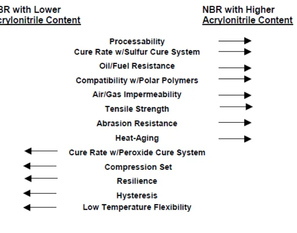
2.6.2 Acrylonitrile (ACN) Content
The ACN content is one of two primary criteria defining each specific NBR grade. The ACN level, by reason of polarity, determines several basic properties, such as oil and solvent resistance, low-temperature flexibility/glass transition temperature, and abrasion resistance. Higher ACN content provides improved solvent, oil and abrasion resistance, along with higher glass transition temperature. Table 1 below summarizes most of the common properties for conventional NBR polymers. The direction of the arrows signifies an increase/improvement in the values.
15
2.6.3 General Types of NBR
2.6.3.1 Cold NBR
The current generation of cold NBR’s spans a wide variety of compositions. Acrylonitrile content ranges from 15% to 51%. Mooney values range from a very tough 110, to pourable liquids, with 20-25 as the lowest practical limit for solid material. They are made with a wide array of emulsifier systems, coagulants, stabilizers, molecular weight modifiers, and chemical compositions. Third monomers are added to the polymer backbone to provide advanced performance. Each variation provides a specific function.Cold polymers are polymerized at a temperature range of 5 to 15°C , (Semon,W.L.,1954) depending on the balance of linear-to-branched configuration desired. The lower polymerization temperatures yield more-linear polymer chains. Reactions are conducted in processes universally known as continuous, semi-continuous and batch polymerization. Figure below shows the chemical structure of NBR, indicating the three possible isomeric structures for the butadiene segments.
16
2.6.3.2 Hot NBR
Hot NBR polymers are polymerized at the temperature range of 30 to 40°C[9]. This process yields highly branched polymers. Branching supports good tack and a strong bond in adhesive applications. The physically entangled structure of this kind of polymer also provides a significant improvement in hot tear strength compared with a cold-polymerized counterpart. The hot polymers' natural resistance to flow makes them excellent candidates for compression molding and sponge. Other applications are thin-walled or complex extrusions where shape retention is important (Horvath, J.W, 1990)
2.6.3.3 Crosslinked Hot NBR
Crosslinked hot NBR’s are branched polymers that are further cross-linked by the addition of a di-functional monomer. These products are typically used in molded parts to provide sufficient molding forces, or back pressure, to eliminate trapped air. Another use is to provide increased dimensional stability or shape retention for extruded goods and calendered goods. This leads to more efficient extruding and vulcanization of intricate shaped parts as well as improved release from calender rolls. These NBR’s also add dimensional stability, impact resistance, and flexibility for PVC modification. (Horvath, J.W, 1990)
2.6.3.4 Carboxylated Nitrile (XNBR)
17
strength, measured by improved tensile, tear, modulus and abrasion resistance. The negative effects include reduction in compression set, water resistance, resilience and some low-temperature properties
2.6.3.5 Bound Antioxidant NBR
Nitrile rubbers are available with an antioxidant polymerized into the polymer chain (Kline, R, 1974). The purpose is to provide additional protection for the NBR during prolonged fluid service or in cyclic fluid and air exposure. When compounding with highly reinforcing furnace carbon black the chemical reactivity between the polymer and the pigment can limit hot air aging capability. Abrasion resistance is improved when compared with conventional NBR, especially at elevated temperatures. They have also been found to exhibit excellent dynamic properties (Horvath, J.W, 1990)
2.7 Polybutadiene (BR)
2.7.1 Properties and Applications
18
nonetheless three times more puncture-resistant than rubber gloves (Crystal and Garry, 2008). However, low Tg also leads to poor wet traction properties, so BR is usually blended with other elastomers like natural rubber or SBR for tread compounds. BR also has a major application as an impact modifier for polystyrene and acrylonitrile-butadiene-styrene resin (ABS) with about 25% of the total volume going into these applications. Typically about 7% BR is added to the polymerization process to make these rubber-toughened resins (see picture below). Also, about 20,000 metric tons worldwide of “high cis” polybutadiene is used each year in golf ball cores due to its outstanding resiliency. This application is growing since the golf ball industry seems to be moving away from the traditional wound ball technology to the two-piece, solid core construction (Mackey and Jorgensen, 1999)
Figure 2.5: Electronmicrograph (5,600X) Rubber-toughened polystyrene resin with BR
19
2.7.2 Chemistry and Manufacturing Process
Polybutadiene is a homopolymer (only one monomer) of 1,3 butadiene, a monomer containing four carbon atoms, and six hydrogen atoms (C4H6). The four carbon atoms are in a straight chain containing two “double bonds” as follows:
CH2=CH-CH=CH2 1,3 butadiene
20
economical. In both processes, the finished product is usually in the form of bales which weigh from 50 to 75 pounds each (Hoffman, 1964)
2.7.3 High Cis Polybutadiene
The alkyllithium and transition metal catalysts make very different products. The transition metal, or so called Ziegler catalysts produce very
“stereoregular” BRs with one type having the main polymer chain on the same side of the carbon-carbon double bond contained in the polybutadiene backbone. This is called the cis configuration.
Figure 2.6: High Cis Polybutadiene
High cis BR will usually have cis content >95% which gives rise to better “green strength” and increased cut growth resistance in the cured product. Green strength, which is the strength of the uncured rubber compound, is important for the tire building process and cut growth resistance is necessary for tire performance. Cut growth resistance is the resistance to the
21
properties of all the high cis types. The cobalt system produces a highly branched BR with a low solution viscosity that makes a good polystyrene and ABS modifier. The nickel catalyst makes BR with an intermediate level of branching (Kline, 1974)
2.7.4 Lithium-based Polybutadiene
The alkyllithium or “anionic” catalyst system produces a polymer with about 40% cis, 50% trans and 10% vinyl when no special polar modifiers are used in the process. The alkyllithium process is probably the most versatile, because the growing chain end contains a “living” anion (negative charge) which can be further reacted with coupling agents or functional groups to make a variety of modified BRs. It also produces gel-free BR making it ideal for plastics modification. Vinyl increases the Tg of the polybutadiene by creating a stiffer chain structure. Vinyl also tends to crosslink or “cure” under high heat conditions so the high vinyl polymers are less thermally stable than low vinyl. Note above, that in vinyl units the double bonds are pendent to the main chain, giving rise to the special properties of high vinyl polymers. Vinyl units can be increased in lithium-based anionic polymerization through the use of polar modifiers, which are usually nitrogen or oxygen-containing compounds. The modifiers direct the attack of the propagating anion on the “living” chain end to give a 1,2 addition to the butadiene monomer.
CH3 – CH==CH – CH2 – (CH2 – CH==CH – CH2)n – CH2 – CH==CH – CH2 Li ⊕
Growing “living” anion (negative charge) on end of live polybutadiene chain with Lithium counterion (positive charge) (Kline, 1974)
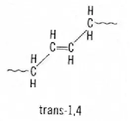
2.7.5 High Trans Polybutadiene
22
in the trans configuration the main polymer chain is on opposite sides of the internal carbon-carbon double bond. Trans BR has a melting point of about 80C. It is made with transition metal catalysts similar to the high cis process (La, Nd, and Ni). These catalysts can make polymers with >90% trans again using the solution process. (Kline, 1974)
Figure 2.7: High Trans Polybutadiene
2.8 Styrene Butadiene Rubber (SBR)
23
concentration of 1,4 trans units has a strong influence on the strain induced crystallization of the rubber, which means a reinforcing effect on the tensile ultimate properties: in this sense, natural rubber shows a strain induced crystallization behavior. Moreover, the relative concentration of 1,4 and 1,2 units may influence the thermal stability of the polymer. The oxidative degradation of the rubber starts from the addition of oxygen on a double bond: if the double bond id part of the main chain, as in the case of 1,4 units, the reaction will lead to a chain scission.
2.9 Polymer
Nowadays, the polymer industry has grown to be larger than the metals industries, as polymers have already had a range of applications in nowadays industry. These included adhesive, coatings, foams and even to packaging materials to textile and industrial fibers industry. Polymer is a large molecule (macromolecule) composed of repeating structural units typically connected by covalent chemical bonds. Plastic is the most synonyms with this term and this term actually refers to a large class of natural and synthetic materials with a variety of properties. Polymers have become an essential and ubiquitous role in everyday life due to the extraordinary range of properties accessible in polymeric materials, from plastics and elastomers on the one hand to natural biopolymers such as DNA and proteins that are essential for life on the other. A simple example is polyethylene, whose repeating unit is based on ethylene (IUPAC name ethene) monomer. Most commonly, as in this example, the continuously linked backbone of a polymer used for the preparation of plastics consists mainly of carbon atoms.
24
polystyrene, polyethylene, polypropylene, polyacrylonitrile, PVB,silicone, and many more.(Wikipedia 2009)
2.10 Epoxy
Epoxy or polyepoxide is a thermosetting polymer formed from reaction of an epoxide "resin" with polyamine "hardener". Epoxy has a wide range of applications, including fiber-reinforced plastic materials and general purpose adhesives.
2.11 Chemistry of Epoxy
Epoxy is a copolymer; that is, it is formed from two different chemicals. These are referred to as the "resin" and the "hardener". The resin consists of monomers or short chain polymers with an epoxide group at either end. Most common epoxy resins are produced from a reaction between epichlorohydrin and bisphenol-A, though the latter may be replaced by similar chemicals. The hardener consists of polyamine monomers, for example Triethylenetetramine (TETA). When these compounds are mixed together, the amine groups react with the epoxide groups to form a covalent bond. Each NH group can react with an epoxide group, so that the resulting polymer is heavily crosslinked, and is thus rigid and strong.
The process of polymerization is called "curing", and can be controlled through temperature, choice of resin and hardener compounds, and the ratio of said compounds; the process can take minutes to hours. Some formulations benefit from heating during the cure period, whereas others simply require time, and ambient temperatures.
25
CHAPTER 3
METHODOLOGY
3.1 Introduction
Methodology means to describe on the overall processes and component that involved in the whole scope of the study to achieve the objective of the study. This includes raw material characterization, sample preparation, mechanical testing, and analysis of the result obtained. The purpose of having a methodology is some of system of broad rules from which specific method and procedure to make sure this report complete.
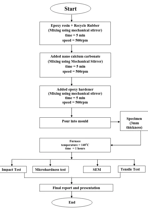
3.2 Flow Chart of Methodology
This project is start from preparing of sample by adding the epoxy resin with recycle rubber with ratio 1 : 0.4. The material were stir using mechanical stirrer at speed 500rpm until it mixed. After that nano CaCO3 powder will added with 5 different
weight percent (0%, 2%, 4%, 6%, and 8%).. The nano-CaCO3 powder was added and
mixed using the mechanical stirrer mill at speed 500 rpm for another 5 min. Then the hardener were added in the same manner, at speed 500 rpm for 5 min. After the mixture is prepared, this mixture will poured into the mould and then wait about 5 hour until it cured. Then the sample will cured inside the furnace and be heated at 140 °C for 1 hour . The resultant nano CaCO3 + epoxy composite reinforced recycle
rubber of about 3 mm in thickness. After that, the mechanical properties of samples will analysis using Shimadzu Universal Tensile Machine AG-1, Scanning Electron Microscope (SEM), impact test and microhardness test.
26
Figure 3.1 : Process Flow Chart
Start
Epoxy resin + Recycle Rubber (Mixing using mechanical stirrer)
time = 5 min speed = 500rpm
Added nano calcium carbonate (Mixing using Mechanical Stirrer)
time = 5 min speed = 500rpm
Added epoxy hardener (Mixing using mechanical stirrer)
time = 5 min speed = 500rpm
Furnace temperature = 140oC
time = 1 hours
Impact Test
Pour into mould
Final report and presentation
End
Tensile Test SEM
Specimen (3mm thickness)
27
3.3 Sample preparation
The materials used in this project are nano calcium carbonate powder (nano CaCO3),
recycle rubber (BR and SBR), epoxy resin and epoxy hardener. These materials are mixed using vary nano CaCO3 powder particle size and percent content. The
nano-size calcium carbonate (nano-CaCO3) used in this study, 20nm, was supplied by
Maju Tek.
The compounding formulations are summarized in Table 1. The mixing ratio of the epoxy, hardener, recycle rubber and nano CaCO3 powder was kept constant for all experiments as 1:0.7:0.4 by weight, respectively. In this study five different weight percent (0%, 2%, 4%, 6%, and 8 wt%) of nano CaCO3 powder will be vary too.
Table 3.1 : Compounding formulation
Weight % of
Nano CaCO3
Weight (gram)
Epoxy Resin Epoxy
Hardener
Recycle
Rubber
Nano CaCO3
Powder
0 100 70 40 0
2 100 70 40 4.2
4 100 70 40 8.4
6 100 70 40 12.6
28
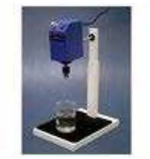
3.3.1 Mechanical Stirring
The tecycle rubber rubber, epoxy resin, epoxy hardener and nano CaCO3 were performed using a mechanical stirring and heated at temperature 60 °C for 5 min. The recycle rubber and epoxy resin was added and mixed using the mechanical stirrer mill at speed 500 rpm for 5 min. Then nano-CaCO3
powder were added in the same manner, at speed 500rpm for 5 min. Beside that the mechanical stirring also been applied to give the shear force to make this mixture fully homogenized.
Figure 3.2 : Mechanical Stirrer Apparatus
3.3.2 Furnace
A furnace can heat materials, typically metals, to very high temperatures and carry out processes such as brazing, sintering and heat treatment with high consistency and low contamination.
29
• Uniform temperatures in the range 2000–2800°F (1100–1500°C) • Temperature can be controlled within a small area
• Low contamination of the product by carbon, oxygen and other gases • Quick cooling (quenching) of product.
• The process can be computer controlled to ensure metallurgical repeatability.
Heating metals to high temperatures normally causes rapid oxidation, which is undesirable. A vacuum furnace removes the oxygen and prevents this from happening
3.3.3 Differential Scanning Calorimetry
Differential Scanning Calorimetry (DSC) is a powerful analytical tool which directly measures the stability and unfolding of a protein, lipid, or nucleic acid. In DSC, the biomolecule is heated at a constant rate and there is a detectable heat change associated with thermal denaturation. DSC measures the temperatures and heat flows associated with transitions in materials as a function of temperature or time in a controlled atmosphere. This technique provides quantitative and qualitative information about physical and
chemical changes that involve endothermic or exothermic processes, or changes in heat capacity.
In a single DSC experiment, can determine: • Transition midpoint - Tm
• Enthalpy (ΔH) and heat capacity change (ΔCp) associated with unfolding
30
(ΔH) and entropy (ΔS) changes. A positive ΔG indicates the native state is more stable than the denatured state – the more positive the ΔG, the greater the stability. For a protein to unfold, stabilizing forces need to be broken. Conformational entropy overcomes stabilizing forces allowing the protein to unfold at temperatures where entropy becomes dominant.
DSC measures ΔH of unfolding due to heat denaturation. The transition midpoint Tm is the temperature where 50% of the protein is in its native
conformation and the other 50% is denatured. The higher the Tm, the more
stable the molecule. During the same experiment DSC also measures the change in heat capacity (ΔCp) for denaturation. Heat capacity changes associated with protein unfolding are primarily due to changes in hydration of side chains that were buried in the native state, but become solvent exposed in the denatured state.
Many factors are responsible for the folding and stability of native biopolymers, including hydrophobic interactions, hydrogen bonding, conformational entropy, and the physical environment (pH, buffer, ionic strength, excipients, etc.)
31
3.3.4 Scanning Electron Microscope (SEM)
The Scanning Electron Microscope is enabling to examination of the surface morphology (Abdolldhi et al, 2009) and microstructure of the sample. The sample is the oxidised aluminium alloy and titanium alloy. The microstructure of oxidised aluminium alloy and titanium alloy was investigated to look the surface feature and characterize the oxide layer thickness of the sample.
SEM magnify is about 10x to 500Kx and the resolution is 1.5nm is very good to look morphology shape and size of the particles making up the sample. The SEM expands the resolution range by more than two orders of magnitude to approximately 4 nm in routine instruments, with ultimate values below 1 nm. The SEM typical operates at 2 to 50kV and the electromagnetic lenses are used to from a small diameter electron probe. A set of scan coils raster the electron probe over the specimen surface as an electron beam scans the inside of the CRT screen. Figure 3.5 is show the SEM machine.
Figure 3.4 : Scanning Electron Microscope (UTeM)
32
3.3.5 Tensile Test
In this project, tensile machine that used is Shimadzu Universal Tensile Machine AG-1 (100kN). First of all, machine test will be prepared based on manual of the machine. Then, the gage length marking of test specimen should be determined. This step must be done to determination of elongation must be accordance with product specification.
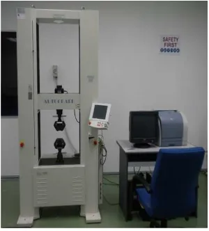
Figure 3.5 : Shimadzu Universal Tensile Machine AG-1
Next step, sample will be grip at testing machine. The grip will be lowered according with the specimen sizes. Machine speed must be set depend on sample condition before the machine started. At the same time, student must follow all instruction regarding tensile machine operation setting that shown by technician.
From the theory, when there occur strain on the specimen is roughly forces imposed, then to test the strength of the rubber, specimen can be calculate using tensile strength, and tensile modulus, E formula.
(a) Tensile Strength,
ε
33 (b) Tensile Modulus, E
E (MPa) = Tensile Stress (
σ
) Tensile Strain (ε
)3.3.6 Impact Test
Impact testing is designed to measure the performance of an object under high-rate loading. It can be a method for evaluating the toughness and notch sensitivity of engineering materials. It is usually used to test the toughness of metals, but it also used for polymers, ceramics and composites. The notched test specimen is broken by the impact of a heavy pendulum or hammer, falling at a predetermined velocity through a fixed distance. The test measures the energy absorbed by the fractured specimen.
Generally, impact testing can be classified into two categories. There are low velocity and high velocity impact test. Low velocity impact test is generally done by using a drop-hammer or swinging pendulum involving a relatively large mass. While for the high velocity impact, it is using a gas gun or some other ballistic launcher which is mainly concern with small masses. For low velocity impact testing, there have two types of testing commonly used which are the Izod and Charpy test. They have been used to measure the impact performance of materials particularly with respect to brittle or ductile transition temperature and notch sensitivity. For Izod test, it is consists a rectangular or square cross section bar of specified dimensions is clamped at one end and struck towards the top of the test piece with a pendulum. For this project, it will focus on Charpy test only.
34
deformation at a relatively low temperature, a high strain rate, and a triaxial stress rate. In addition, the notched test specimen is broken by the impact of a heavy pendulum or hammer, falling at a predetermined velocity through a fixed distance in impact testing.
3.3.7 Charpy Test
The Charpy impact test is a standardized high strain-rate test of standard notched specimen which determines the amount of energy absorbed by a material during fracture. This absorbed energy is a measure of a given material's toughness and acts as a tool to study temperature-dependent brittle-ductile transition. Materials are used to build load-bearing structures. It is important to know if the material will survive the conditions that the structure will see in service. Important factors that adversely affect the toughness of a structure include low-test temperatures, extra loading and high strain rates due to over pressurization or impacts and the effect of stress concentrations such as notches and cracks. These all tend to encourage fracture.
35
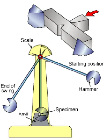
Figure 3.6 : Apparatus for Charpy impact testing
For the Charpy test, the specimen is in the shape of square cross section was machining to V- notch. The load that applied as an impact is blow from a cooked position at a fixed height, h. The specimen is positioned at the base as shown. Upon release, a knife edge mounted on the pendulum strikes and fractures the specimen at the notch, which acts as a point of stress concentration for this high velocity impact blow. Then, the pendulum will continues swing, until rising to a maximum height h’,
which is lower than its original height, h. (Ling Yih Lii, 2009)
Figure 3.7 : The standard V-notched Charpy test specimen
36
shape. The notch in the sample also affects the results of the impact test, thus it is necessary for the notch to be of a regular dimensions and geometry. The Charpy impact tests determine the fracture properties of materials which may be used for design purposed.
3.3.8 Hardness Test (Vickers Micro Hardness)
37
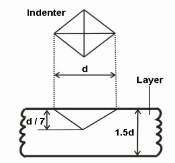
d: Diagonal length t : Minimum layer thickness (1.5d)
h: Indentation depth ( d/7) 4d: Minimum distance to next print
2.5 d: Minimum distance to specimen edge
F: Force Kgf
HV = 0.1891 F/d2
Figure 3.8: Indentation depth and equation of Vickers micro hardness on coating or substrate.
38
CHAPTER 4
RESULTS AND DISCUSSIONS
4.0 Introduction
In this chapter, all the data and results will be presented to see the effect of nano-CaCO3 on mechanical properties of epoxy composite reinforced recycle rubber. In
this chapter also will be discussed the reason why all the specimen behave the way it gave it mechanical properties and how does the nano-CaCO3 change their morphology
structure. There were three tests that conducted in order to determine the mechanical properties of the specimen. The tests that conducted were tensile tests, microhardness tests and Charpy tests. In this chapter also will be discussing the results and interpreted it.
4.1 Tensile Tests Results and Discussion
The tests were conducted on the recycle rubber and nano-CaCO3 toughened epoxy
composite with different percentage weight % of nano-CaCO3. The tensile tests
were conducted using Universal testing machine (UTM). The main objective for this test is to determine the maximum stress, load, displacement, Young Modulus that acting on this material. This test is also to study the behavior of the specimens under different axial load.
39
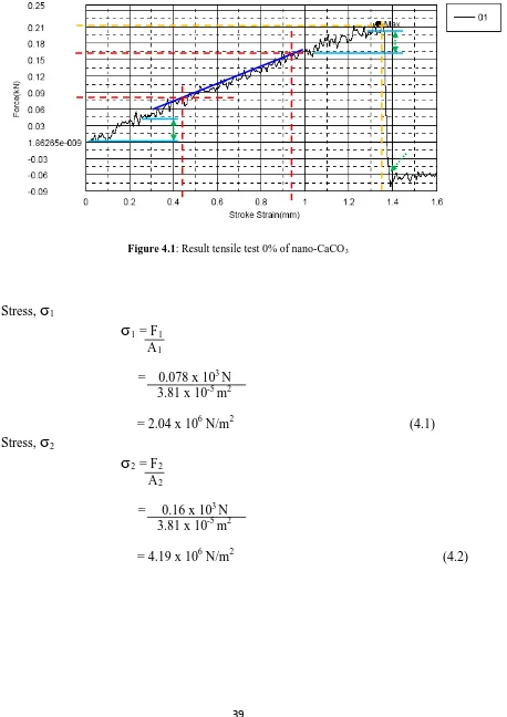
Figure 4.1: Result tensile test for 0% weight of nano CaCo3
Figure 4.1: Result tensile test 0% of nano-CaCO3
Stress,
σ
1σ
1 = F1A1
= 0.078 x 10³ N 3.81 x 10⁻⁵ m2
= 2.04 x 10⁶ N/m2 (4.1) Stress,
σ
2σ
2 = F2A2
= 0.16 x 10³ N 3.81 x 10⁻⁵ m2
40
Strain,
ε
ε
= S2 – S1S1
= 0.95 x 10⁻³m – 0.44 x 10⁻³ m
0.44 x 10⁻³ m
= 1.16 (4.3)
Young Modulus, E
E =
σ
2 -σ
1ε
= 4.19 x 10⁶ N/m2 – 2.04 x 10⁶ N/m2
1.16
= 1.853 MPa (4.4)
Stress maximum
σ
max
= FmaxA
= 0.214 x 10³ N 3.81 x 10⁻⁵ m2
= 5.617 x 10⁶ N/m2
41
Figure 4.2: Result tensile test 2% weight of nano CaCo3
Figure 4.2: Result tensile test 2% of nano-CaCO3
42
Figure 4.4 : Result tensile test 6% of nano-CaCO3
43
Table 4.1 : Tensile Test Result
% wt of
Figure 4.6 : The graph maximum stress vs wt % of nano-CaCO3
0
44
Figure 4.7 : The graph tensile stress vs wt % of nano-CaCO3
Figure 4.8 : The graph Young’s Modulus vs wt % of nano-CaCO3
0
Tensile Strain vs wt % of nano-CaCO
345
The results of the testing are shown by Table 4.1 that is the average value of the tensile tests. There were three samples tested for each type of specimens, which is reinforced to different percentage weight in order to get accurate results. As we can see from Table 4.1, specimen with the highest percentage of nano CaCo3 (8%) has the highest maximum stress (22.64MPa). As the
percentage of nano CaCO3 increase, the tensile stress also increases
consequently. We can say that the nano CaCO3 is directly proportional to tensile
stress. This also can be proven by the trend of the graph plotted as shown in Figure 4.1 where higher the percentage of CaCO3, higher the value of tensile
stress. If compare the highest percentage (8%) to the lowest percentage (0%), there is a different about 22.64% which we have proven that nano CaCO3 affect
the tensile strength of the material.
For the second graph as shown in Figure 4.7 that been plotted for tensile tests results, the graph tensile strain versus percentage of nano CaCO3 shown
trend that almost similar to tensile stress versus wt% of nano CaCO3 has positive
slope. As the nano CaCO3 is increase, the tensile strain is increase. Hence, we can
say that tensile strain is directly proportional to the nano CaCO3. The highest
strain that we got from the tensile is 0.0044 m that from the highest value of wt % nano CaCO3. This is due to highest nano CaCO3 specimen behave more
ductile that causing it can elongate longer compare to others specimens. And for the last graph (Figure 4.8) that Young’s Modulus versus nano CaCO3, the
trend of the graph is similar with the first two that we plotted. It shown that as nano CaCo3 increase, the Young’s Modulus will increased. This can be proven
by equation of Young’s Modulus where the Young’s Modulus is inversely proportional to tensile strain.
As a conclusion, as the percentage of nano CaCO3 increase, the tensile
46
4.2 Charpy Test Result
Charpy test was conducted to determine the amount energy that has been absorbed by the different percentage of nano Caco3. Table 4.2 shows
the result of the energy absorbed with different percentage specimens using pendulum impact test machine. From the Table 4 . 2 , we noticed that the h i g h e s t p e r c e n t a g e w e i g h t o f n a n o C a C O3
h a s t h e h i g h e s t e n e r g y absorbed that is 0.80J meanwhile the lowest energy absorbed by the specimen is 0.36J that been absorbed by specimen with 0% weight nano CaCO3. The reason why the specimen
absorbed more energy due to they have a lots of small spherulites with a lot of grain boundaries. This is because the spherulites do not have the chance to grow due to increasing of nano CaCO3, make their size is small. As the
specimens have a lot of small grain boundaries, it hard for the crack to propagate due to grain boundaries impede the crack. Hence, it needed bigger energy to break if compared to the one with lower nano CaCO3. As a
conclusion, the amount of energy absorbed by the specimens can be used to measure the fracture toughness of the material and the yield strength.
Table 4.2 : Energy Absorbed vs Nano CaCO3 (%)
Nano CaCO3
(%)
Energy absorbed (Joule) by pendulum impact test
Sample 1 Sample 2 Sample 3 Average
0 0.4 0.4 0.3 0.36
2 0.5 0.4 0.5 0.47
4 0.5 0.5 0.6 0.53
6 0.7 0.5 0.7 0.63
47
Figure 4.9 : The graph energy absorbed versus nano CaCO3
If a specimen fails with shear lips or jagged edges, it means that the fracture is ductile meanwhile if the specimen fails on flat plat, it means the fracture is brittle. By comparing the shape of failure of the specimen will give us estimation of the failure mode for our Charpy specimens. For Figure 4.9(e), the specimen that have the highest percentage of nano CaCo3, the fracture shows
jagged edge and not a straight line. This is because it was not easy to break the specimen, hence it needed more energy to fracture it compare for lower percentage of nano CaCO3 specimens . Hence the specimen behave as ductile.
As the percentage of nano CaCo3 increase, the energy needed are higher to break
the specimen. As for the specimens with lower percentage of nano CaCo3,
from Figure 4.9(a) to Figure 4.9(d), we can see the fracture mode is in straight line or flat plane at failure area. The straight line or flat plane means that the fracture needed a small energy to propagate the crack to fracture and the specimens is weak. For the specimen with lower percentage of nano CaCO3 will
behave like this.
48
Figure 4.9(a) Charpy failure mode with 0% of nano CaCO3
Figure 4.9(b) Charpy failure mode with 2% of nano CaCO3
Figure 4.9(c) Charpy failure mode with 4 % of nano CaCO3
Figure 4.9(d) Charpy failure mode with 6 % of nano CaCO3
49
4.3 Microhardness Test
Table below shows the microhardness of the samples. Based from figure below, at each specimen, the values of hardness increase when the percentages of nano CaCO3
increase. The highest hardness occurs at 8% of nano CaCO3 and 0% nano CaCo3 have
the lowest amount of hardness.
Based from the trend obtained from results, it shows that the increasing of nano CaCO3
gives high value of hardness. The trend is applicable for all sample. For example sample of 8% weight gives the maximum value for each ratio. Hence, it can be conclude that the increased of percentage of Nano CaCO3 will increased the hardness of sample produced.
50
4.4 Specimen’s Microstructure Study
Different percentage of nano CaCO3 have caused variation of degree of
crystallinity and appearance samples due to different structural morphology formed. The structural morphology that is changes are the spehrulites which have different sizes due to different percentage of nano CaCO3. This morphology
structure change will be discussed in this section and how this change affecting the mechanical properties of the specimens. The spehrulites structure can be assessed by using scanning electron microscope (SEM).
As a result, the specimens that have higher mechanical properties as more energy needed to fail the specimens. We can see from the result of experiments, the specimens with highest weight percentage of nano CaCO3 show greater tensile
and flexural stress and also tensile and flexural strains. Due to fine crystals structure and no weak site, more energy needed to fracture the specimens. As for the Young’s Modulus of this specimens, it is lower due to the degree of crystallinity is low.
As for the specimens with l o w e r w e i g h t p e r c e n t a g e o f n a n o C a C o3
condition, the specimens have big spherulites, and there is greater contraction or shrinkage of the crystalline region during and after cooling which leads to the formation of “retraction voids” between the spherulites boundaries at the tetrahedral junction. This is because as the spherulites grow bigger, they will impinge on each other and form the boundary line. These boundaries become the “weak site” and cracks and voids simultaneously forms in the area are due to shrinkage of the bulk polymer. Hence, the existence of retraction voids between the spherulites boundaries partly causing the weakness of this specimen. As a result, the weakness of the structure is causing the tensile stress and strain needed is lower compare to one with high weight percentage of nano CaCO3. As
51
specimens are lower compare to the one with increasing nano CaCO3. This is
because of the existence of the voids causing lesser energy needed to break the weak sites such micro cracks and voids. For this specimen with lower weight percentage of nano CaCO3 has higher value of Young’s Modulus due to have
high percentage of degree of crystallinity. As the degree of crystallinity higher, the material will have higher stiffness. Hence, it will have higher Young’s Modulus value if compared to highest percentage of nano CaCO3 specimen.
For the lower weight percentage of nano CaCO3, it will have longer
crystallization time causing more time for the segregation of “impurities” such as low molecular weight species accumulate between the spherulite boundaries. This high concentration of the impurities likely to accumulate near the retraction voids. The combination of both voids and “impurities” will weaken the structure of the material. The voids are the major reason of inter-spherulatic fracture of large –spherulite specimens. This is because the voids are the first reason cracks been initiated in the structure, and the crack will propagate to where boundary regions are weak. Hence it cause the lower in certain mechanical properties compare to increasing nano CaCO3 specimens.
As we increase the nano CaCO3, we can see improvement in impact strength of
the specimens compare the one without calcium carbonate fillers that been conducted by Ling Yih Lii, 2009. By increasing the weight percent of nano CaCo3 to the epoxy composite resulted in a large number of nucleuses and
52
53 SAMPLE
(wt% of
CaCO3)
MAGNIFICATION
21 X 500 X 1.00 K X
0%
2%
54 SAMPLE
(wt% of
CaCO3)
MAGNIFICATION
21 X 500 X 1.00 K X
4%
6%
55 SAMPLE
(wt% of
CaCO3)
MAGNIFICATION
21 X 500 X 1.00 K X
8%
56
CHAPTER 5
CONCLUSIONS AND RECOMMENDATIONS
5.0 CONCLUSIONS
After all the testing and result analysis, it can be concluded that the objective to determine the effect of nano-CaCO3 to mechanical properties of e p o x y
c o m p o s i t e r e i n f o r c e d recycle rubber has been achieved. All the mechanical properties of these specimens were determine by conducting the tensile test, impact test, Scanning Electron Microscope (SEM) and microhardness test. The effects of nano-CaCO3 towards mechanical properties of epoxy
composite can be explained by the analysis of the microstructure.
The whole experiment and the study effect of nano- CaCO3 towards
mechanical properties can be summarized as below:
1. The tensile stress of polymer matrix composite are been affected by the nano CaCo3. Higher nano CaCo3 produced higher tensile stress and
tensile strain. The maximum stress obtained at higher nano CaCo3 is
22.64 Mpa
2. The tensile strain increase as the nano-CaCo3 is increase.
Material behaves more ductile as the nano-CaCo3 is increase.
3. The tensile strain is decrease as nano CaCo3 increase. This means the
57
4. For the Charpy test, more energy been absorbed by specimen with high nano CaCo3. The most energy absorbed is by the highest nano
CaCo3 (8%) that is 0.8J. This is due to higher energy needed as the
structure has very fine crystal structure with no weak site.
5. As we increased the nano CaCo3 to the epoxy composite, certain
mechanical properties such as and impact strength are been improved if compared to pure composites samples.
5.1 RECOMMENDATIONS
To further the investigation of the mechanical properties , some modifications can be suggested to improve the understandings of such material hence lots of study to improve its properties can be done in the future. Thus, some recommendations were suggested for this study as follow:
1. This study only uses 3 mm thickness of specimen to obtain the material’s properties. Hence, for the future study, the specimens can be prepared with different thickness.
2. This study just added 0-8% of nano calcium carbonate fillers to the epoxy composite, for the future study specimens can be prepared with various percentage of fillers and study the effects to the mechanical properties.
58
REFERENCES
"Solvay Precipitated Calcium Carbonate: Production". Solvay S. A.. 2007-03-09.
Cristina Buzea, Ivan Pacheco, and Kevin Robbie (2007). "Nanomaterials and Nanoparticles: Sources and Toxicity". Biointerphases 2: MR17.
Crystal, Garry (2008). "What are Nitrile Gloves?". wise GEEK. Conjecture Corporation. http://www.wisegeek.com/what-are-nitrile-gloves.htm. Retrieved 2008-02-05.
Freeman, Gary M. (Macon, GA), Moritz, Randal A. (Lizella, GA), Jones, William J. (Lizella, GA), Moller, Kurt H. (Warner Robins, GA)",(2002) "Processes for preparing precipitated calcium carbonate compositions and the products thereof",
Hofmann,W., NITRILE RUBBER, Rubber Chemistry and Technology, A RUBBER REVIEW for 1963, 154-160 (1964).
Horvath, J.W., Paper No. 18, Dynamic Properties of Nitrile Rubbers, Presented at Rubber Division Meeting, ACS, Las Vegas, Nevada (1990).
Ibid., 71.
Kahn, Jennifer (2006). "Nanotechnology". National Geographic 2006 (June): 98–119.
59
Kline, R. Polymerizable Antioxidants in Elastomers, Presented at Rubber Division Meeting, ACS, Toronto, Canada (1974).
Mackey, D. and Jorgensen, A.H., Elastomers, Synthetic (Nitrile Rubber), Kirk-Othmer Concise Encyclopedia of Chemical Technology, 4th Edition, 687-688 (1999).
N. Taniguchi (1974). On the Basic Concept of 'Nano-Technology. Proc. Intl. Conf. Prod. London, Part II British Society of Precision Engineering.
Nallick P K, Fiber-reinforced Composites : Materials, Manufacturing and Design (Marcel Dekker Inc, New York) 1993
Patnaik, Pradyot (2003). Handbook of Inorganic Chemical Compounds. McGraw-Hill. ISBN 0070494398
Semon,W.L., NITRILE RUBBER, SYNTHETIC RUBBER, Division of Chemistry, American Chemical Society, 802-3 (1954).
Solvay Precipitated Calcium Carbonate: Production. Solvay S. A. (2007-03-09). Retrieved on 2007-12-30.
Table 14, Nitrile Dry Rubber (NBR), IISRP Synthetic Rubber Manual,13th Edition, (1995).
Table 2, Worldwide Long Term New Rubber Consumption Forecast by Elastomer Type, IISRP Worldwide Rubber Statistics (2001).
http://www.wisegeek.com/what-is-styrene-butadiene-rubber.htm (accessed : 6 September 2010)