SUPERVISOR DECLARATION
“ I hereby declare that I read this thesis and in my opinion this thesis is sufficient in terms of scope and quality for the award of the degree of
Bachelor of Mechanical Engineering (Plant & Maintenance)”
Signature :………
Supervisor name : DR. MOHD KHAIRI BIN MOHAMED NOR
CONTROL DESIGN OF AN ADAPTIVE PROSTHETIC LEG FOR AMPUTEES USING MAGNETO-RHEOLOGICAL DAMPER
MOHD RIDZUAN BIN JUMA’AT
A thesis submitted in partial fulfilment of the requirement for the award of the degree of
Bachelor of Mechanical Engineering ( Plant& Maintenance)
Faculty of Mechanical Engineering Universiti Teknikal Malaysia Melaka
ii
DECLARATION
“ I hereby declare that the work in this thesis is my own except for summaries and quotation which have been duly acknowledged ”
Signature :………
Author : MOHD RIDZUAN BIN JUMA‟AT
iii
iv
ACKNOWLEDGEMENT
v
ABSTRACT
This project is a about the development and designing control artificial limbs passive to semi active for those who are physically handicapped. Installation of this artificial leg will connect the top of the knee. The amputation can occur in various factors which include the effects of an accident or illness that involve imperfect circulation such as diabetes. The proposed design of prosthetic limbs with a design that has a magneto-rheological (MR) damper where this damper will replace the missing leg muscle that functioned from the knee to the ankle . Before the damper is applied, all damper properties should be identified in advance. Bouc - Wen model is the best model for the description of the hysteresis nature of MR damper. Control strategy used for this process is the development of prosthetic limbs using proportional, integral and derivatives (PID) controller. Generally, the system response in entirely unstable in open-loop form. The criteria to get the stability of the system are (i) settling time,
T
s for of less than 5 seconds and (ii) pendulum anglevi
ABSTRAK
vii
TABLE OF CONTENTS
CHAPTER TITLE PAGE
DECLARATION ii
DEDICATION iii
ACKNOWLEDGEMENT iv
ABSTRACT v
ABSTRAK vi
TABLE OF CONTENTS viii
LIST OF TABLES xi
LIST OF FIGURES xiii
LIST OF ABBREVIATIONS/SYMBOLS xiv
LIST OF APPENDIX xvi
CHAPTER 1 INTRODUCTION 1
1.1 Project Background 1
1.2 Problem Statement 2
1.3 Objective 3
viii
CHAPTER TITLE PAGE
CHAPTER 2 LITERATURE REVIEW 5
2.1 Magneto-rheological (MR) Fluids 5 2.2 Magneto-rheological (MR) Damper 6 2.3 Magneto-rheological (MR) Damper
Behaviour 8
2.4 Inverted Pendulum 9
2.5 PID Controller 11
2.6 Root Locus 12
CHAPTER 3 METHODOLOGY 13
3.1 Modelling System For Inverted
Pendulum 13
3.1.1 Force Analysis And System
Equation 15
3.2 Modelling System For MR
Damper 21
3.3 Simple Bouc-Wen Model 22
3.4 Modified Bouc-Wen Model 23
3.5 Generation Of Bouc-Wen Model 24
ix
CHAPTER TITLE PAGE
CHAPTER 4 RESULT AND DISCUSSION 29
4.1 System Analysis 29
4.2 PID Controller 31
4.3 Root Locus 34
CHAPTER 5 CONCLUSION AND RECOMMENDATION 39
5.1 Conclusion 39
5.2 Recommendation 39
REFERENCE 41
x
LISTOFTABLES
TABLE TITLE PAGE
2.1 Component of MR damper and its function 7 3.1 Parameters for inverted pendulum in modelling system 14
3.2 Parameters for generalized model 25
4.1 Effect of Increasing the PID Gain
K
P,K
I andK
D onxi
LISTOFFIGURES
FIGURE TITLE PAGE
2.1 Schematic diagram of lateral MR damper design 6 2.2 Predicted force-displacement behavior using the
numerical model proposed by Spencer 8
2.3 Predicted force-velocity behavior using the numerical
model by Spencer 9
2.4 Inverted pendulum 10
3.1 An inverted pendulum mounted on a cart 14
3.2 System dynamics in a movable cart 15
3.3 Free body diagram of the cart 15
3.4 The simple Bouc-Wen model of MR damper schematic 22 3.5 The modified phenomenological Bouc-Wen model of
MR damper schematic 23
3.6 Nonlinear Bouc-Wen
model 26
3.7 Overall dynamics 26
3.8 Linearized model 27
3.9 Pendulum model 27
xii
FIGURE TITLE PAGE
3.11 Combination of PID controller an Inverted pendulum 28
4.1 Open-loop impulse response 29
4.2 Open-loop step response 30
4.3 Response of pendulum position to an impulse disturbance under PID control;
, 1
p
K
K
i
,1
K
d
1
314.4 Response of pendulum position to an impulse disturbance under PID control;
, 100
p
K
K
i
,1
K
d
1
32 4.5 Response of pendulum position to an impulsedisturbance under PID control; 4.6 Response of cart position to an impulse
disturbance under PID control;
, 100
p
K
K
i
,1
K
d
20
34 4.7 Root locus of plant (under proportional control) 354.8 Root locus with integral control 35
xiii
FIGURE TITLE PAGE
4.10 Response of pendulum angle to an impulse
disturbance under PID control 37
4.11 Response of cart position to an impulse
xiv
L
IST OFABBREVIATION/SYMBOL
a = Bouc-Wen model parameter related to the MR material
yield stress
0
k
= Spring stiffness0
c
= Dashpot damping coefficient respectivelyz = Hysteretic deformation of the model A = Bouc-Wen model parameter
a
= Third-order polynomial ab
xv
L
IST OFABBREVIATION/SYMBOL
n = Parameter for power
= Viscosity of fluidc
M
= Mass of the cartp
m = Mass of the pendulum b = Friction of the cart I = Inertia of the pendulum
l = Length to the pendulum‟s center of mass F = Impulse force applied to cart
P = Reaction force on the pivot from vertical direction
xvi
LIST OF APPENDIX
NO APPENDIX TITLE PAGE
A Gantt Chart For PSM 1 46
B Milestone For PSM 1 47
C Gantt Chart For PSM 2 48
D Milestone For PSM 2 49
E Flow Chart For PSM 50
F M-File Command Matlab (PID) 51
G M-File Command Matlab (Root Locus) 55
1
CHAPTER1
INTRODUCTION
1.1 PROJECT BACKGROUND
Every part of our body plays an important role in implementing the daily activities such as walking, running and etc. But not everyone in this world are so lucky because of some unwanted situation or disease. There are number of reasons that cause them to need an amputation. The common ones include the circulation problem from atherosclerosis or also known as diabetes. The traumatic injuries also the common cause including from traffic accidents and military combat. While for cancer is the least causes among others.
2
The proposed design of prosthetic leg featuring magneto-rheological (MR) damper in which the damper is able to replace the missing leg muscles from knee to ankle. Magneto-rheological (MR) damper have a component of MR fluid, a pair of wires, housing, a piston, a magnetic coil and an accumulator. MR fluid have been discovered by Jacob Robinow in the 1940s, of which yield stress and viscosity varies in the presence of magnetic field, various applications using MR fluid have been developed such s shock absorbers, clutches, engine mounts, haptic devices and structure dampers, etc (Kim et al., 2002).
Magneto-rheological fluid is called a smart material because of its properties can be controlled by applying a magnetic field whose consistency can be rapidly switched to any intermediate state between liquid and solid. The MR fluid consists of suspension of fine magnetically polarisable particles in a carrier medium such as mineral oil and silicone oil. When a magnetic field is applied to the MR fluids, it will align themselves in chains along the field lines. The value of fluid viscosity will affect the damping characteristics of the damper system. Due to the road or track irregularities, MR fluid is used to control the damping characteristics of the damper according to the force acting on it. This property can be used to control the stiffness and viscous damping. Therefore, the prosthetic leg for amputees featuring magneto-rheological damper will offer effective performance over a variety of amplitude and frequency range.
1.2 PROBLEM STATEMENT
3
joint and muscle pain caused by irregular surface. When they do some extreme activities such as going up and down slopes, it will affect their movement. According to Professor Michael Goldfarb, it was tough to make the prosthetic leg light and quite enough. In addition, the biggest technical challenge, however, was to develop the control system. Furthermore, one of the members from the faculty has designed and introduced a MR damper based prosthetic leg in order too make the user fell comfortable. The proposed control method for the prosthetic leg is using Proportional Integral Derivative (PID) controller. This prosthetic leg featuring magneto-rheological (MR) damper is classified as semi-active devices. Semi-active devices are characterized by their ability to dynamically vary their properties with a minimal amount of power ( Housner et al., 1997; Spencer and Sain, 1997). The controller has to perform individual operation reliability, but also it has to perform several operations at the same time and not to get confused. Therefore, the most consideration to be taken is the development of mathematical modeling and control system for magneto-rheological (MR) damper.
1.3 OBJECTIVE
The objective for this project as shown as below :
4
1.4 SCOPE
i) Study the control strategies for prosthetic leg featuring magneto-rheological (MR) damper.
ii) Propose the suitable mathematical modeling and controller for magneto-rheological (MR) damper.
5
CHAPTER2
LITERATUREREVIEW
2.1 MAGNETO-RHEOLOGICAL (MR) FLUIDS
6
2.2 MAGNETO-RHEOLOGICAL (MR) DAMPER
A schematic diagram of a typical MR damper is illustrated in Figure 2.1. There are three main types of MR damper which are mono-tube, twin-tube and double-ended tube. In this research, the mono-tube damper is set as the fundamental concept of MR damper design. A MR damper commonly consists of a mono-tube house, wire with magnetic coil, floating, piston, piston rod, valve, oil seals, upper cover, lower cover, mounting bracket, pressurized gas inside the accumulator and magneto-rheological fluid. The force desired by the system to be controlled will determine the size of the MR damper.
Figure 2.1 :Schematic diagram of lateral MR damper design
Upper cover functions as to seal the top of MR damper to prevent the flow out of MR fluid from the cylinder. The mounting bracket is designed and fabricated on the upper cover. During compression and extension as the movement of piston, there are two oil seals working to prevent the MR fluid flow out of the cylinder at the upper cover. The oil seals also serve to keep out dust from entering the cylinder.
7
The design of floating piston is to separate the two different medium between MR fluids and pressurized air. As mention before, the installation of two oil seals on the floating piston to prevent the mixing of MR fluid and pressurized air. In order to initiate pressurized air into the cylinder then valve is used. The accumulator was applied about four bar of pressurized air into the MR fluid damper. The leaking of pressurized air from the cylinder can be prevented by the design of lower cover. The installation of MR damper on the test rig can be facilitate easily by mounting bracket. All the function of each MR damper components are summarized in the Table 1 below :
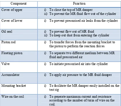
Table 2.1:Component of MR damper and its function
Component Function
Cover of upper i) To close the top of MR damper
ii) To prevent the MR fluid flow out of the cylinder Cover of lower i) To prevent pressurised air leaks from the cylinder
Oil seal i) To prevent flow out of MR fluid
ii) To keep out dust from entering the cylinder Piston rod i) To transfer forces from the mounting bracket to
the piston to perform the reaction forces
Floating piston i) To separate two different medium between MR fluid and pressurised air
Valve i) To initiate pressurised air into the cylinder
Accumulator i) To apply air pressure to the MR fluid damper
Mounting bracket i) To facilitate the MR damper easily installed on the test rig