STABILITY AND THERMAL CHARACTERISTICS OF CARBON NANOFIBER (CNF) WATER-BASED NANOFLUIDS
NOR SALIHAH BINTI ZAINI
SUPERVISOR DECLARATION
“I hereby declare that I have read this thesis and in my opinion this report is sufficient in terms of scope and quality for the award of the degree of Bachelor of
Mechanical Engineering (Thermal-Fluid) with Honours”
Signature:
ii
DECLARATION
“I hereby, declare this project entitled
‘Stability and Thermal Characteristics of Carbon Nanofiber (CNF) water based nanofluids’ is the result of my own research except as cited in the reference”.
Signature :
iii
Special tribute to my beloved parents;
iv
ACKNOWLEDGEMENT
v
ABSTRACT
vi
ABSTRAK
vii
TABLE OF CONTENTS
CHAPTER TITLE PAGE
SUPERVISOR DECLARATION i
DECLARATION ii
DEDICATION iii
ACKNOWLEDGEMENT iv
ABSTRACT v
ABSTRAK vi
TABLE OF CONTENT vii
LIST OF FIGURE x
LIST OF TABLES xii
LIST OF APPENDICES xiii
CHAPTER I INTRODUCTION
1.0 Background 1
1.1 Problem Statement 2
1.2 Objectives 2
1.3 Scope Of Study 2
CHAPTER II LITERATURE REVIEW
2.0 Introduction 3
2.1 Nanofluid Preparation 4
viii
CHAPTER TITLE PAGE
2.2 Nanofluid Application 6
2.2.1 Heat Transfer Application 6
2.2.2 Nuclear Reactor 7
2.2.3 Cancer Therapeutics 7
2.2.4 Automobiles 8
2.3 Nanomaterials 8
2.3.1 Carbon Nanotubes 9
2.3.2 Carbon Nanofiber 10
2.4 Water-Based Nanofluid 11
2.5 Dispersing Agent 11
2.6 Stability of Nanofluid 12
2.6.1 Sediment and Centrifuge Method 12 2.6.2 Surfactant Used in Nanofluid 13 2.6.3 Effect of Homogenization 14 2.6.4 Effect of Sonication 15
2.7 Thermal Conductivity 16
2.8 Viscosity 17
2.9 Heat Transfer Coefficient 18
CHAPTER III METHODOLOGY
3.0 Introduction 19
3.1 Flowchart 20
3.2 Parameter Used in Experiment 21
3.2.1 Deionized Water 21
3.2.2 Type of CNF Used 21 3.2.3 Dispersing Agent Properties 22
3.3 Apparatus 22
3.3.1 Homogenizer 22
3.3.2 Ultrasonicator 23
ix
CHAPTER TITLE PAGE
3.3.6 Viscometer 25
3.3.7 Data Logger 26
3.3.8 Thermocouple 26
3.4 Experimental Procedure 27
3.4.1 Nanofluid Formulation 27
3.4.2 Thermal Conductivity Test 28
3.4.3 Heat Transfer Coefficient Test 29
3.4.4 Viscosity Test 30
3.5 Safety Precaution 30
CHAPTER IV RESULTS AND DISCUSSION 4.0 Introduction 31
4.1 Results and Discussion 31 4.1.1 Stability of Nanofluid 31
4.1.2 Thermal Conductivity Test 33
4.1.2.1 Percent Enhancement 35 4.1.3 Viscosity Test 37
4.1.4 Heat Transfer Test 40
4.1.4.1 Percent Enhancement 42 CHAPTER V CONCLUSION 5.0 Conclusion 46
5.1 Recommendation 47
REFERENCES 48
x
LIST OF FIGURES
NO TITLE PAGE
2.1 One-Step preparation process 5
2.2 Two-Step preparation process 6
2.3 Several structures of carbon based material 9
2.4 Graphical Structures of SWCNT and MWCNT 10
2.5 Morphology of carbon nanotube 10
2.6 Polivinylpyrrolidone (PVP) Molecular Structure 12
2.7 Formation of stable nanofluid 14
2.8 Nanoparticles size distribution for water containing
0.1wt% SWCNH 14
2.9 Nanoparticles size distribution for water containing
0.1wt% TiO2 15
2.10 Thermal conductivity data of ND-Ni nanofluids 16 2.11 Viscosity properties of nanofluids and base fluid 18
3.1 Flowchart 20
3.2 Homogenizer 23
3.3 Ultrasonic cleaning unit 23
3.4 (a) Stability test rig 24
3.4 (b) The condition of the stable nanofluid 24
3.5 KD2-Pro thermal properties analyzer 25
3.6 Viscometer 25
3.7 Pico Data Logger 26
3.8 Experiment set-up for thermal conductivity test 29
3.9 (a) Copper Coil 29
3.9 (b) Experiment set-up for heat transfer test 29
xi
NO TITLE PAGE
4.1 Graph of thermal conductivities of different wt% of
CNF 33
4.2 Trend of thermal conductivities of each samples 34 4.3 (a) Enhancement of thermal conductivity at 6 ͦC 36 4.3 (b) Enhancement of thermal conductivity at 25 ͦC 36 4.3 (c) Enhancement of thermal conductivity at 40 ͦC 36 4.4 The viscosity of different sample of CNF 38 4.5 Trend of viscosity according to the temperature
increment
39
xii
LIST OF TABLES
NO TITLE PAGE
3.1 Properties of deionized water 21
3.2 Pyrograf III HHT properties 22
4.1 Ratios of CNF, dispersing agent and deionized water 32
4.2 Result of thermal conductivities 33
4.3 Percentage of enhancement for thermal conductivity 35
4.4 Data of viscosity reading 38
4.5 Temperature of inlet and outlet for heat transfer analysis at
6 ͦC 41
4.6 Temperature of inlet and outlet for heat transfer analysis at
25 ͦC 41
4.7 Temperature of inlet and outlet for heat transfer analysis at
40 ͦC 41
4.8 Average temperature difference of samples at 6 ͦC, 25 ͦC and
40 ͦC 42
xiii
LIST OF APPENDICES
APPENDIX TITLE PAGE
A Gantt’s chart of the study 52
B Sample calculation of formulation 53
1
CHAPTER I
INTRODUCTION
1.0 BACKGROUND
Nanofluids are dilute liquid suspensions contain nanometer-sized particles that have the dimension within 1-100 nanometers. This fluid has been engineered in order to enhance the thermophysical properties in a particular system. Thermophysical properties include thermal conductivity, thermal diffusivity, viscosity, and convective heat transfer coefficients. They are the main properties to be considered in industries nowadays since it is widely used for cooling process in engineering application. Basically the formation of nanofluid begins by the addition of nanomaterial to a based fluid like water, or oil. Carbon nanofiber (CNF) is type of nanomaterial that have excellent mechanical properties, high electrical conductivity and high thermal conductivity, which can be imparted to a wide range of matrices including thermoplastics, thermosets, elastomers, ceramics, and metals. The addition of CNF inside the based fluid will form the carbon nanofluid. However the selection of based fluid is varies and from the previous studies, water is one of the best based-fluid used in the formation of nanobased-fluid.
2
1.1 PROBLEM STATEMENT
Nanoparticles such as carbon nanofibers (CNF) can have superior thermal conductivity compared to other element such as aluminium oxide and titanium oxide. The addition of CNFs to a fluid could improve the heat transfer properties. However, the major problem when using CNFs is their stability and dispersion in nanofluids system. Agglomeration can lead to inaccurate and non-reproducible data. Therefore, it is important to conduct experiment to find the best method to overcome this problem.
1.2 OBJECTIVES
The objectives of the study are:
i. To study the stability, dispersion and thermal characteristics of Carbon Nanofibers (CNF) water-based nanofluids.
ii. To identify the most stable CNF Water-based nanofluid formulation with enhanced performance
1.3 SCOPE OF STUDY
The scopes of work are as shown;
i. Formulation of nanofluids which consists the mixture of Carbon Nanofibers (HHT-24), Polyvinylpyrrolidone (PVP) and deionized water.
ii. Identification of the optimum ratio of CNF, PVP and deionized water in order to achieve stability.
3
CHAPTER II
LITERATURE REVIEW
2.0 INTRODUCTION
4
2.1 NANOFLUID PREPARATION
Preparation of nanofluid is the crucial step in experimental studies of the nanofluid stability. The correct step should be considered since it affects the result on nanofluid studies. The primary step in nanofluid preparation involves single-step preparation process and two-step preparation process.
2.1.1 Single-Step Preparation Process
5
Figure 2.1: One-step preparation chemical process (Source : Mukherjee et al. 2013)
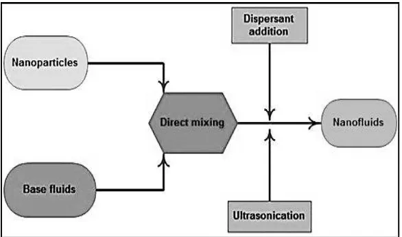
2.1.2 Two Step Preparation Process
6
Figure 2.2: Two-step preparation process (Source : Mukherjee et al. 2013)
2.2 NANOFLUID APPLICATION
There are many applications of nanofluid that has been used recently. These include the usage in industry, fuel application, power plant as well as medication. Its pleasant function in heat transfer application had caught the attention of the recent technologist and industrialist to broaden it usage and application on the other sector in the future. Other than that, the discovery of nanofluid also provides the contribution for the world sustainability.
2.2.1 Heat Transfer Application
7 a shell and tube heat exchanger under turbulent flow condition. From the result obtained, adding of nanoparticles to the base fluid causes the significance enhancement of heat transfer properties. For the other types of heat exchanger, Huminic (2011) run a three-dimensional analysis to study the heat transfer characteristics of a double-tube helical heat exchanger using nanofluids in laminar flow condition. The result obtained shows the enhancement of heat transfer rate of the nanofluid approximately about 14% greater than of pure water at the same mass flow rate in inner tube and annulus. While the heat transfer rate of water from annulus than through the inner tube flowing nanofluids was approximately 19% greater than for the case which through the inner and outer tubes flow meter.
2.2.2 Nuclear Reactors
Kim et al. (2007) do the research to determine the feasibility of nanofluids in nuclear applications by improving the performance of any water-cooled nuclear system that is heat removal limited. Possible applications include pressurized water reactor (PWR) primary coolant, standby safety systems and so forth. The using of nanofluids instead of conventional liquid based causes one of the components in PWR that is fuel rods become coated with nanoparticles such as alumina, which prevent any formation of bubbles and finally result in the elimination of a layer of vapor around the rod. The use of nanofluids as a coolant could also be used in emergency cooling systems, where they could cool down overheat surfaces more quickly leading to an improvement in power plant safety (Wong & Leon, 2010). The use of nanofluids in nuclear power plants seems like a potential future application (J. Boungiorno et al. 2007).
2.2.3 Cancer Therapeutics
8 to J. Boungiorno (2007), magnetic nanofluids are to be used to guide the particles up the bloodstream to a tumor with magnets. It will allow medical officers to apply high local doses of drugs or radiation without damaging nearby healthy tissue.
2.2.4 Automobiles
The nanofluid applications for automobiles are enormously wide. The applications involves are coolant, fuel additives, lubrication, shock absorber and brake fluids. Cooling process is very important in automotive sector because it directly related to engine performance. However the bulky size of the conventional radiator causes the rapid dissipation of heat to the surrounding otherwise, it requires some investment due to the complex manufacturing and the cost to consider the amount of material used. According to Mishra et al. (2011) high heat dissipation
results in larger radiators and increase frontal areas leading to additional viscous drag and rise in engine fuel consumption. According to the statement, it clearly explained that the systems in automotives crucially need an efficient coolant to remove more engine heat from higher horsepower engines with a relatively small radiator. By the existence of nanofluid, this issue can be solved due to their large surface area that enhances the rate of heat transfer process in the radiator. Moreover, the size of the radiator can be much smaller than the conventional one and this created the flexibility for the movement of automotive vehicle.
2.3 NANOMATERIALS
9 Based on Agency (2013), there are commonly four types of currently used nanomaterial such as carbon based materials, metal based materials, dendrites and composite. Carbon based material shape have the long hollow shape which consists mainly of carbon. Most carbon based material taking the form of a hollow spheres, tubes, or ellipsoid. Spherical and ellipsoidal carbon nanomaterials are known as fullerenes, while cylindrical tubes form is called carbon nanotubes (Azo, 2013). Figure 2.3 shows the several structures of carbon based material.
2.3.1 Carbon Nanotubes
Carbon Nanotubes (CNTs) are long cylinders of covalently bonded carbon atoms which possess extraordinary electronic and mechanical properties (Choudhary & Gupta, 2011). There are two basic types of CNTs those are single-wall carbon nanotubes (SWCNTs) and multi-wall carbon nanotubes (MWCNTs) as shown in Figure 2.4. SWCNTs are the fundamental cylindrical structures while multi-wall carbon nanotubes is a multiple layer of SWCNTs. Carbon nanotubes are tiny little microscopic-sized tubes made of sheets of carbon atoms, rolled up into a tube like a paper towel roll. One roll is a single walled carbon nanotube and a few rolls will make a MWCNT (Sass, 2014).According to Choundary et al. (2011), MWCNTs are made of coaxial cylinders and having interlayered spacing close to that of the interlayer distance in graphite about 0.34 nm.
(a) Graphene
Figure 2.3 : Several structures of carbon-based material. (Source: Lulu et al. 2014)
10
2.3.2 Carbon Nanofiber
Carbon Nanofibers (CNFs) is a novel carbon nanomaterial where the structure of graphene sheets are stacking in varying shape which then producing more edges sites on the outer wall of CNFs. The CNFs edges sites is more compared to CNTs edges sites. According to Huang et al. (2010) this advantage can facilitate the electron transfer of electroactive analytes. Carbon nanofibers (CNFs) have the similar conductivity and stability to carbon nanotubes (CNTs) however the primary differences between the materials are morphology, size, ease of processing and costs. Carbon nanofibers, also known as Stacked-Cup Carbon Nanotubes (SCCNT) have a unique morphology in that graphene planes are canted from the fiber axis, resulting in exposed edge planes on the interior and exterior surfaces of the fiber (Choundary
et al. 2011). In other words, Stacked-Cup Carbon Nanotubes is morphological
structures of Carbon Nanofibers. The Figure 2.5 illustrates the difference in CNF and CNT morphology.
Figure 2.4: Graphical Structures of SWCNT and MWCNT (Source: Choudhary & Gupta, 2011)
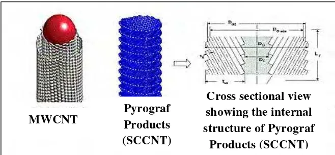
Figure 2.5: Morphology of Carbon Nanotube (Source : Choundary et al. 2011)
SWCNT MWCNT
MWCNT
Pyrograf Products (SCCNT)
Cross sectional view showing the internal structure of Pyrograf