DOI: 10.12928/TELKOMNIKA.v14i4.4184 1329
Implementation of Innovative Technologies in the
Fields of Electronic Locks
Štefan Koprda1, Martin Magdin*2
Department of Computer Science, Faculty of Natural Sciences,
Constantine the Philosopher University in Nitra, Tr. A. Hlinku 1, 949 01 Nitra, Slovakia *Corresponding author, e-mail: [email protected], [email protected]
Abstract
Almost every institution currently uses attendance system that ensures maintaining control over the attendance of employees, students and other persons. By using attendance system we can provide the right to enter certain rooms for only designated people. On the basis of reports from attendance system we can evaluate a monthly attendance of employees and the by that determine their real movement within the institution. Today is this system the usual standard in every medium and large institution, for example businesses, schools, universities and many others. The price for such a system, however, is often too high. Therefore companies opt also for other alternatives. Our task was to create a working prototype of such a system. Such a system must dispose at least with function for indicating the arrival and departure of employees to be able to determine the time of stay in the workplace. For this purpose we used the platform of microcontroller Arduino with a several basic sensors and software Arduino IDE. In this paper we present the achieved results in terms of applying different access cards.
Keywords: Arduino, RFID, RFID reader, electronic lock
Copyright © 2016 Universitas Ahmad Dahlan. All rights reserved.
1. Introduction
RFID-based monitoring and tracking system is a complex, integrated system that offers an effective solution of managing items especially for large scale environment [1]. It combines the RFID technology and security devices to ensure the items are always monitored and secured remotely. The system enables the organization to track and monitor selected individual to access locations inside the university, permit movement, record the data of arrival/departure and also enable the viewing of record via this system [2].
Radio Frequency Identification (RFID) has been an emerging technology in recent years. In the recent few years there have been a lot of advancements in the field of RFID. The given RFID system consists of two fundamental components: tags and readers. The reader and the tag communicate via the transmission of electromagnetic waves. A reader is what the user interfaces with to transmit information to and from the tag, and tends to be much larger than the tag [3].
RFID tag is known as a proximity integrated circuit card [4] and it can be powered actively or passively. RFID tags are also known as transponder and one transponder consist of antenna, microchip and battery (for active tag only). The size of the chip generally depends on the antenna size. Antenna size and form is dependent on the frequency that is used by the tag. Active tag contains on board power source where passive tags are inductively powered via Radio signal that is generated by RFID reader. Active tag can work in absence of reader and records the sensor readings or performs their calculation. Passive tags can operate in presence of reader only [5].
When the chip was nearby to the magnetic field transmitted by the external antenna of the reader, the chip was able to draw enough energy from the electromagnetic field for the power supply of its own electronics. In the moment the chip was connected, it was able to modulate the magnetic field which was captured by the reader. This way it was possible for the chips to transfer data to the reader. Many types of chips exist which may work on various frequencies [6].
Identification (ID) of each object. This ID acts as a serial number stored in the RFID memory. The range of RFID tags depends on their frequency. These frequency ranges are Low Frequency (30-500 KHz), High Frequency (10-15MHz) and Ultra High Frequency (2.4- 2.5GHz). Other performance attributes and resistance to interference is determined by this frequency [7].
Currently have begun to occur similar solutions worldwide. Therefore is the trend to leverage the maximum from the minimum. That means, we know that a minimum of hardware and economic requirements achieve the same efficiency of solutions as in the case of robust solutions from large companies.
A typical example is the Staff Control System (SCS) in Kazakhstan that was proposed by Saparkhojayev and Kurymbayev in 2015. This system is already used successfully in practice two years at the State Kazakhstan University. These authors [2] indicate that the access tag can be read up to 10 centimetres from the RFID reader.
RFID Reader is also known as a Proximity Coupling device (PCD) and it reads the data through the tag antenna at a certain frequency [4]. In case of passive tag the reader generates a radio signal so that the passive tag can energize and transmit the signal that can be read by the reader. The reader translates the received information and passed it to the forwarded system through wired or wireless communication. A single reader can read the data from multiple frequency based tags [7].
Compared to other automatic identification technologies, and especially, compared to optical barcode systems, RFID-technology has important advantages, and among of them, the most important one is the following: tag data can be read automatically beyond the line of sight, through certain materials, and from a range of several meters [8].
In our paper we describe a possibility of design and realization of similar system. But we focus on the fact that not all RFID readers know how to evaluate signal from a standard distance of 10 cm. There are different types that operate on the same frequency, but not with the same success.
2. Using Microcontroller Arduino as the Control Element
Nowadays for the automation and control process (which is also the attendance system) are used the most commonly programmable control automats. Their main advantage is that they are versatile and modular. According to Lacko et al. [9], automation is nowadays one of the most dynamic fields. It uses the most advanced microelectronic components and uses the most current results from various fields such as computer science, electrical engineering, communication technology, but also measurement technology and security technology.
The basic unit of each control automat is a microcomputer. It contains inputs and outputs. With using inputs and outputs processes information and so properly acts to the control system. This property has also a microcontroller Arduino. Microcontroller Arduino is modular control system and this microcontroller can communicate with other devices of the same type or other devices.
According to Besson et al. [10] these boards are able to record different types of events associated with electrical [11], optical [12] or mechanical signals [13, 14].
Microcontroller Arduino is most often used particularly on the automation of small systems due to the wide range of modules (Shields). These modules can be easily connected to the motherboard of microcontroller Arduino [15].
programming is done via computer simulated serial interface. For connection of additional modules (shields) we can use several I/O pins on the motherboard.
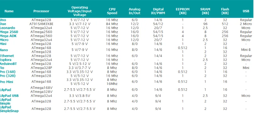
Figure 1. A comparison of the different versions of microcontroller Arduino
Arduino provides an integrated development environment (IDE) that is capable of running on all major operating systems and has support for a simplified C/C++ programming language. Arduino also has a large online community that stimulates engagement in development and enables rapid prototyping and debugging [16].
The development environment of microcontroller Arduino (IDE) is multiplatform application which is programmed in Java. This development environment is designed so that in it could work even people with minimal of Java programming knowledge. The development environment of microcontroller Arduino includes a code editor with standard features such as syntax color coding, automatic alignment and pairing of brackets. It is able to compile the created program and upload it to Arduino with one click on a button. The program for the Arduino we call sketch.
Arduino programs are written in C or C ++. The development environment of microcontroller Arduino (IDE) contains a library of functions that facilitates writing the most basic hardware operations. The user must define two basic functions to create an executable program:
setup(): function that is triggered only once at the beginning of the program and is used to set
parameters
loop(): function that is periodically triggered, if the microcontroller is connected to a power
source.
3. Design and Implementation of Functional Attendance System
This proposed system is dedicated to secure access to the building. In the next development phase of the system is possible to extend this system with the section that will inform the user or administrator when and who entered or left the room (the building). For the realization of the automatic opening and closing doors and creating attendance system we used microcontroller Arduino Mega ADK, reader MFRC 522, servomotor and UPS (backup source). On the Figure 2 is a block diagram of the device, which was proposed.
smooth and safe transition to a backup in case of power failure. For normal power supply we use stabilized power supply with the following parameters: Input voltage for microcontroller Arduino and the remaining parts of the system is 6V and electric current 1200 mA. The structural design of the UPS (backup source) is in Figure 3.
Figure 2. Block diagram of attendance system, which includes the electronic lock
Figure 3. The simple backup source
Explanation:
C – 1000mF – electrolytic capacitor on 10 V R – 1000Ω
D - Schottky diode 2A
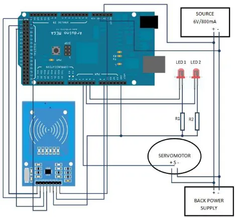
The real connection of our system is in Figure 4. It consists of a microcontroller Arduino Mega ADK, card reader and LED indicators. LED indicators inform the user of each state of the system, about each state of servo motor and the backup source.
Figure 4. The real connection of attendance system with the electronic lock
Figure 5. MFRC 522 chip
4. Evaluation and Discussion of the Obtained Results
In design, construction and realization of electronic lock that is part of attendance system, we have received a request for enabling input of users by using different ways - with card Mifare S50 and plastic key tags RFID. In testing, however, we noticed that the reading and evaluation of the approach is not always correct. Therefore, we focused on determining the conditions in which the system can more reliably to evaluate the data in process reading the card or plastic key tags RFID.
We conducted therefore a series of six (3 on the card and 3 for plastic key tags RFID) following measurements for the chip card and plastic key tags RFID:
1. The RFID reader is placed in a plastic housing - part of the entrance door,
2. RFID reader is not located in a plastic housing - direct connection with a "live" part of the RFID reader,
3. The plastic housing of door was replaced with glass panes.
Each series of measurements consisted of 100 attempts. We have changed the distance (0-2cm, 3-5cm, 6-10cm) from the RFID reader. In one series were realized for a total of 300 measurements.
5. Evaluating the Success of Reading Plastic Key Tags RFID
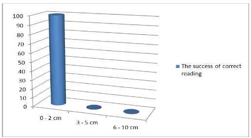
The first series of measurements was conducted to determine the ability to retrieve data from the plastic key tags RFID. RFID reader was placed in a plastic housing, which was part of the entrance door to secure protection against external adverse effects.
From the chart, which is shown in the Figure 6, you can see that at a distance of 0-2cm, plastic key tags RFID is working properly at each of the 100 measurements. At a distance of 3-5cm and 6-10cm RFID reader failed to distinguish the plastic key tags RFID in these distances.
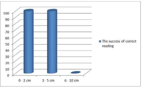
The second series of measurements was conducted to determine the ability to retrieve data from the plastic key tags RFID, but RFID reader is not located in a plastic housing - we created direct connection with a "live" part of the RFID reader.
Figure 7. Dependence of reading data from distance by using the plastic key tags RFID (direct connection with a "live" part of the RFID reader)
From the chart, which is shown in the Figure 7, you can see that at a distance of 0-2cm, plastic key tags RFID is working properly at each of the 100 measurements. At a distance of 6-10cm RFID reader failed to distinguish the plastic key tags RFID. At a distance of 3-5 cm we achieve an interesting result when the RFID reader from 100 different measurements was 40 times unable to load the plastic key tags RFID.
The third series of measurements was conducted to determine the ability to read data from the plastic key tags RFID - the plastic housing of door was replaced with glass panes.
Figure 8. Dependence of reading data from distance by using the plastic key tags RFID (The plastic housing of door was replaced with glass panes)
6. Evaluating the success of reading card Mifare S50 with RFID reader
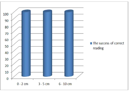
The first series of measurements was conducted to determine the ability to retrieve data from the RFID card with a mark Mifare S50. RFID reader was placed in a plastic housing, which was part of the entrance door to secure protection against external adverse effects.
Figure 9. Dependence of reading data from distance by using the RFID card Mifare S50 (RFID reader was placed in a plastic housing)
From the chart, which is shown in the Figure 9, you can see that at a distance of 0-2cm, RFID card Mifare S50 is working properly at each of the 100 measurements. At a distance of 3-5 cm we achieve an interesting result when the RFID reader from 100 different measurements was 42 times unable to load the plastic key tags RFID. At a distance of 6-10cm RFID reader failed to distinguish the plastic key tags RFID in these distances.
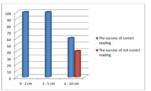
The second series of measurements was conducted to determine the ability to retrieve data from the RFID card Mifare S50, but RFID reader is not located in a plastic housing - we created direct connection with a "live" part of the RFID reader.
Figure 10. Dependence of reading data from distance by using the RFID card Mifare S50 (direct connection with a "live" part of the RFID reader)
Figure 11. Dependence of reading data from distance by using the RFID card Mifare S50 (The plastic housing of door was replaced with glass panes)
From the chart, which is shown in the Figure 11, you can see that at a distance of 0-2cm and 3-5cm, the RFID card Mifare S50 is working properly at each of the 100 measurements. At a distance of 6-10cm we achieve an interesting result when the RFID reader from 100 different measurements was 40 times unable to load the RFID card Mifare S50.
On the basis on these results, we can conclude that both technologies can be used with a 100% success rate at a distance of 0-2 cm. In other cases is the success of reading affected by the type of technology used (plastic key tags RFID/ Mifare card) and placing the RFID reader.
7. Conclusion
The aim of our paper was to highlight the possibility of the effective use of innovative technologies in practice. The proposed system is able to operate as maintenance-free system for opening and closing of doors, and last but not least make a record of the user input / outputs to the building. An important factor in the design of this electronic lock was to ensure that a system was able to work also in the event of a power failure. As a backup source was used its own system (the electrical scheme is shown in Figure 4). In the case of power cut we can mechanically open the electronic lock (with classic key). After restoration of voltage is the system restored to a position before the power failure.
References
[1] Sharma S, Shimi SL, Chatterji S. Radio Frequency Identification (RFID) based Employee Monitoring System (EMS). International Journal of Current Engineering and Technology. 2014; 4(5).
[2] Saparkhojayev N, Kurymbayev A. Implementation of RFID - based computer access system (CAS) for Kazakhstani University. 2015 5th International Workshop on Computer Science and Engineering: Information Processing and Control Engineering, WCSE 2015-IPCE. 2015:1-6.
[3] Kiran BN, Smitha BC, Sushma KN. Implementation Of RFID For Blind Bus Boarding System. International Journal of Scientific Engineering and Applied Science. 2015; 1(3): 443-446.
[4] Baude PF, Ender DA, Kelley TW, Haase MA, Muyres DV, Theiss SD. Organic semiconductor RFID transponders. Technical Digest - International Electron Devices Meeting. 2003:191-194.
[5] SubramanianV, ChangPC, Lee JB, MolesaSE, Volkman SK. Printed organic transistors for ultra-lowcost RFID applications. IEEE Trans. Components Packaging Technol. 2005: 67-71.
[6] Balogh Z, Turčáni M. Complex design of monitoring system for small animals by the use of micro PC and RFID technology. Lect Notes Electr Eng. 2016; 380: 55-63.
[7] Mishra Y, Marwah GK, Verma S. Arduino Based Smart RFID Security and Attendance System with Audio Acknowledgement. International Journal of Engineering Research & Technology. 2015; 4(1): 363-367.
[8] Weis SA, Sarma SE, Rivest RL, Engels DW. Security and privacy aspects of low-cost radio frequency identification systems. Lecture Notes in Computer Science. 2004; 2802: 201-212.
[10] Besson T, Debayle D, Diochot S, Salinas M, Lingueglia E. Low cost venom extractor based on arduino® board for electrical venom extraction from arthropods and other small animals. Toxicon. 2016: 156-161.
[11] Sheinin A, Lavi A, Michaelevski I. StimDuino: An arduino-based electrophysiological stimulus isolator. Journal of Neuroscience Methods. 2015: 8-17.
[12] Anzalone GC, Glover AG, Pearce JM. Open-source colorimeter. Sensors (Switzerland). 2013; 13(4): 5338-5346.
[13] Grenez F, Viqueira Villarejo M, García Zapirain B, Méndez Zorrilla A. Wireless prototype based on pressure and bending sensors for measuring gate quality. Sensors (Switzerland). 2013; 13(8): 9679-9703.
[14] Schubert TW, D'Ausilio A, Canto R. Using arduino microcontroller boards to measure response latencies. Behavior Research Methods. 2013; 45(4): 1332-1346.
[15] Magura D, Fedák V. Využitie systému Arduino pri riadení procesov. ATP Journal. 2012.