DOI: 10.12928/TELKOMNIKA.v14i3A.4413 17
Electric Vehicle Regenerative Braking Control Strategy
Based on Braking Time Identification
Shigang Song*1, Xiaoping Li2, Yong Lin3 1,3
Zhijiang College of Zhejiang University of Technology, Hangzhou, Zhejiang, 310024, PR China
2Narada Power Source Co., LTD, Hangzhou, Zhejiang, 311100, PR China
*Corresponding author, e-mail: [email protected]
Abstract
The angular velocity and displacement variation of the brake pedal with time during braking is studied. Using brake angular velocity as the judgment basis of the moving window algorithm, established the function model between the brake pedal angular velocity and displacement. Regenerative braking time was identified accurately, using brake angular velocity integral quantity. On this basis, analyzed the battery can accept the maximum charge current, with feedback cur-rent as the control object, considering the reasonable distribution of regenerative braking and hydraulic braking force, the regenerative braking control strategy based on braking time was proposed. The tests verify the feasibility and effective-ness of the braking time identification algorithms and the strategy for braking force distribution.
Keywords: Electric vehicle, Braking energy, Braking time, Control strategy
Copyright © 2016 Universitas Ahmad Dahlan. All rights reserved.
1. Introduction
It is an urgent problem to improve the electric energy utilization efficiency and prolong the mileage, as to improve the electric vehicles performance and gradually towards industrialization, and the regenerative braking technology has been used as a key technology for the development of electric vehicles. At present, electric vehicles regenerative braking technology research is mainly concentrated in the control strategy, to get maximum energy recoery under ensure vehicle braking performance [1-3]. It is need to identify the braking intention for taking into account the braking safety and braking energy recovery rate, and allocates mechanical braking force and motor braking force based on identification braking intention.
2. Braking Time Identification
2.1. The Relationship between Brake Pedal Angle Velocity and Displacement
Under different braking conditions, the driver subjective feeling and the vehicle braking performance requirements are different, the braking time is not the same. From the whole braking process, braking time including the driver action reaction time T1, the brake operating time T2, continuous time T3 and relaxation brake time T4, as shown in figure 1. The general braking time is from stepping on the brake pedal to safe parking time, it include the brake operating time T2 and continuous braking time T3.
Figure 1. The Relationships between the braking force, deceleration and braking time
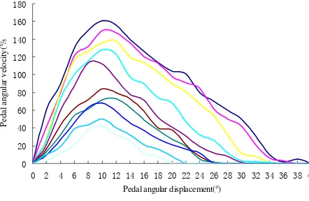
Research has shown that driver braking intention can be identified from brake pedal velocity and displacement, brake pedal force, braking oil pressure and other parameters[9]. According to the pedal angle velocity can distinguish different braking condition, and pedal angle velocity peak value under different conditions could be distinguished on brake work phase, which was well predictable and rapid. However,used the pedal instantaneous angular velocity as identification parameter of braking intention, the sensor performance requirement were high and more interference. Therefore, it was necessary to analyze the relationship between the pedal angle speed and pedal angle displacement. Typical parameters of brake pedal angular velocity extracted from experiment, and collected brake pedal angular displacement, the relationship as shown in figure 2.
Figure 2. The Relationship between the pedal angular velocity and pedal angular displacement
The brake pedal angular velocity to peak in the pedal angle displacement around 10 degrees, which can be seen from the above figure. Driver has braking operation conscious when the pedal angle displacement through the most blank travel. Useing the brake pedal angle
0 20 40 60 80 100 120 140 160 180
0 2 4 6 8 10 12 14 16 18 20 22 24 26 28 30 32 34 36 38 40
Pedal angular displacement(°)
Pe
da
l a
n
gu
la
r ve
lo
ci
ty
(°
velocity as the judgment basis of moving window algorithm in this paper, setting pedal displacement 5 degrees -15 degrees for window width, integral computation of angular velocity in the window, get the angular velocity capacity during braking. This algorithm has the strong anti-interference ability due to the variation of velocity curve much more smooth than the acceleration curve.
Using Newton-Cotes quadrature formula to integral angular velocity signal. Due to the low order Newton-Cotes quadrature formula is not high accuracy, can use complex trapezoid form to calculate. The calculation formula is as follows:
displacement of t angular velocity; h is interval length.
The brake pedal angle velocity reflect the braking speed and urgency, pedal angle displacement is the input signal of composite brake system. There is a certain correlation between the brake pedal angular velocity and angular displacement, which can be seen from Figure 2. Based on the analysis of experimental data, using polynomial to curve fitting of brake pedal angle displacement as shown in formula (2):
3
2.2. Braking Time Recognition Method based on Angular Velocity Integral
Get the relation curve between hydraulic pressure of the wheel cylinder pw and pedal displacement D by test, wheel cylinder pressure as a function of the pedal displacement, namelypw f(D). In the vehicle will not slip, the relation between ground braking force and braking pedal angular velocity is following:
cylinder diameter; r as the equivalent brake radius; R as for wheel radius; as friction coefficient; p0 as the static friction of wheel cylinder pressure conversion.According to the braking speed, braking time can be determined:
In the formula,
v
as the initial speed of braking;m
asvehicle quality. The braking time is determined by the brake pedal angular velocity, through the integral quantity of the brakes phase angular velocity can beforehand identify braking time.3. Regenerative Braking Model 3.1. Braking Force Distribution Model
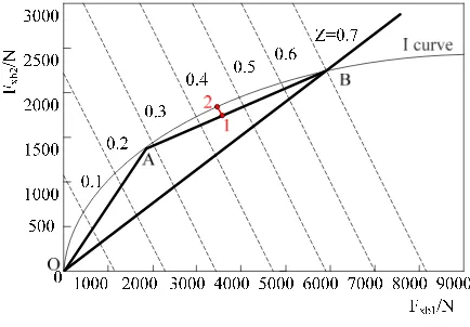
often used with a fixed ratio of front and rear brake force distribution line instead of the ideal, as in Figure 3 straight line OB. However,with front and rear brake fixed ratio, the actual distribution of braking force and ideal braking force distribution line discrepancy is very great, the braking efficiency is low. Therefore, made variable proportional valve hydraulic distribution line instead of the ideal braking force distribution curve as shown in Figure 3, it consists of OA line and AB line two sections [10,11].
In a target braking intensity, according to above braking force distribution method get the front and rear axle actual braking point 1, and ideal braking force point 2 under same braking intensity. When the actual braking force point 1 is closer to the ideal braking force point 2, the braking efficiency higher.Therefore, by the distance between two points as the braking efficiency index of the braking intensity, the value of the distance as small as possible.
Figure 3. Braking force distribution curve
When considering the total braking efficiency of braking intensity in a certain range, could converted the target as smallest area of between ideal braking force distribution curve (I curve) and the OAB line. Thus, the objective function is
In the formula, G as the vehicle gravity; b for distance of vehicle centroid to rear axle centerline; L for the front and rear axle distance; hg as the vehicle centroid height; XA, YA,
B
X , YB as A and B point coordinate values respectively.
If the I curve and the synchronous adhesion coefficient to a certainty, namely the B point coordinate to certainty. So the first term of formula (5) is a constant value. Thus, the objective function can be transformed into a maximum of second and third item, viz.
XA
XXAB B BThus, could determine A point coordinate value, and get the OAB line. Through the OAB line to approach the ideal braking force distribution curve.
3.2. Motor Regenerative Braking Mathematical Model
When electric vehicle braking, due to external force of traveing in the opposite direction,the speed of the vehicle is reduced gradually until it stops.
In the braing process, resistance force including the rolling resistance Ff , air resistance
w
F , gradient resistance Fi, regenerative braking resistance Fm and hydraulic braking resistance resistanceFh. Thus, the motor regenerative braking force for
) quality; conversion coefficient of vehicle rotating mass; v as the relative velocity of vehicle and air. Braking state, the motor is used as a generator, the vehicle body kinetic energy preserve to battery. In this process, the armature current produce a negative torque braking, thereby reducing the vehicle speed.
When the speed is low or the wheel locking the output shaft of the motor speed is very low, the motor generated small electromotive force, so the motor is difficult to charge the battery. Moreover, for reliable parking which is necessary to adopt hydraulic brake system completely when vehicle speed is very low, and the transition from regenerative braking to the hydraulic brake should achieve a gradual transition, so as to avoid sudden changes in speed. To achieve this, imported motor torque speed influence factor Kfm, expressed as
min
Motor regenerative braking, must consider the safety and use of battery. According to the armature current, the average charging current of feedback battery group as
d
bav I
I (9)
In the formula, for duty ratio.
By formula (7), (8) and (9) can get relationship between battery charging current and motor braking force
t
3.3. Battery Charging Current Model
In order to protect the battery, the battery maximum charging current cannot be greater than its own limited in regenerative braking process. Howerve, there are close relation between battery acceptable charging current and battery internal resistance.
chg chg
b
R
t
z
OCV
u
I
max(
(
))
max
(11)In the formula, OCV(z(t)) as the open circuit voltage of the battery in the current state of charge; Rchg as battery charge internal resistance. Battery charge internal resistance can be
tested by mixed pulse power characteristics test method HPPC, the HPPC method uses a set of discharge and regeneration pulse calculated battery discharge and regeneration internal resistance at different state of charge [12-14].
Power battery group actual used in electric vehicles, which is composed of many single battery series and parallel. Because of the battery manufacturing technology and production conditions limit, single battery charging performance is differenct.
In order to describe accurately the power battery charging performance, made power battery charging uniformity coefficient Ki, the battery group maximum rechargeable current
i chg b chg
total
b
I
K
I
max
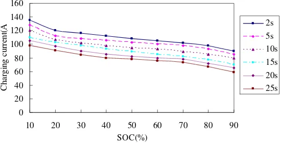
max (12)At the same temperature and SOC conditions, the battery maximum charging current relation with time, the current limit can withstand greater with shorter charging time. Figure 4 shows a 20Ah battery under 25C, charged on 2S, 5S, 10s,15s, 20s and 25s respectively, the maximum charging current curve corresponding to different battery SOC.
Figure 4. Battery maximum charging current under different charging time
When electric vehicle regenerative braking, battery 2S charging capacity correspond to vehicle emergency braking energy feedback; the ability to charge about 10s correspond to vehicle sliding brake energy feedback; the ability to charge about 20s correspond to a downhill braking energy feedback. Through charging time contacted battery charging performance and vehicle braking performance.
4. Braking Energy Feedback Control Strategy
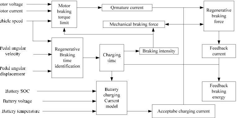
Regenerative braking Control strategy of electric vehicle is the maximum brake energy recovery, which based on the vehicle speed, the brake pedal and the battery status parameters, both and the motor maximum braking power and battery charging capacity. Electric vehicle brake energy feedback control logic based braking time identification as shown in Figure 5, tracking of the charging current dynamicly by identifying the braking time, realizing the unification regulation of regenerative braking and mechanical braking.
In the premise of meeting the braking safety and battery charging reliability, to maximize the recovery braking energy, established the control strategy as flow.
0 20 40 60 80 100 120 140 160
10 20 30 40 50 60 70 80 90
SOC(%)
C
h
ar
g
in
g
cu
rr
en
t(
A 2s
1) According to the brake pedal angle velocity, by formula (1) and (2) determine thepedal angle displacement.
2) Based on the electric vehicle corresponding parameters, with regenerative braking time identification module, by type (3) and (4) determine the regenerative braking charge time and braking intensity.
3) According to the battery SOC, battery voltage, battery temperature and charge time,get the maximum acceptable charging current Ibchgmaxtotal by battery charging current model.
4) In order to protect the battery, opening the regenerative braking when battery SOC less than 0.9 and not more than 0.7, could not opening the regenerative braking in other cases.
5) Used variable proportional valve hydraulic distribution lines to confirm actual braking force of front and rear shaft, and by formula (7) obtaining motor regeneration braking force Fm. Through the armature current, by formula (8) ~ (10) calculated to average charging current of feedback battery pack.
6) Judge the relationship between average charging current Ibav and acceptable
maximum charging current Ibchgmaxtotal. If bav chg
total
b I
I max , using the average charging current
bav
I for charging the battery, otherwise using battery pack acceptable maximum charging
current Ibchgmaxtotal.
7) According to the charging current adjustment to regenerative braking force Fm, if the motor braking force can meet the demand of the braking torque, were all used motor braking; when the motor braking force can not meet the demand braking by supplemented by hydraulic brake.
Figure 5. Brake energy feedback control logic based braking time identification
5. Test Results and Analysis
Figure 6. Relationship between brake pedal angle displacement and braking time
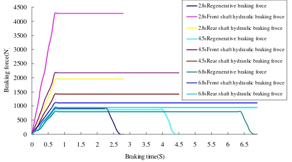
Brake pedal angle displacement were selected as 34 degree, 28 degree and 23 degree, obtain the braking time is 2.8s, 4.5s, 6.8s. According to the real-time SOC, battery voltage and temperature, get the maximum acceptable charging current f 112A, 106A and 98A through the battery charging current model. Thus, could determine the motor maximum braking force, and get the change relationship between the front and rear shaft braking force and braking time as shown in Figure 7 by a variable proportional valve hydraulic distribution line.
Figure 7. Relationship between braking time and braking force
Get different braking time by the braking force as a function of braking time in figure 7, braking force distribution ratio in vehicle corresponding total required braking force as shown in table 1. It can be seen from table 1 that the braking time is longer, the regenerative braking force ratio to total demand braking force increse, the more braking energy recovery. Regenerative braking force ratio minish with the reduction of braking time, because the braking time shorter braking intensity bigger, the battery can accept the maximum charge current increase is limited, when the motor braking force reaches the maximum value, remaining braking by hydraulic brake to supplement.
Table 1. Braking force ratio under different braking time
Braking time(S)
Regenerative braking force Front shaft hydraulic braking force
Rear shaft hydraulic braking force Braking force(N) Ratio(%) Braking force(N) Ratio(%) Braking force(N) Ratio(%) 2.8 920.64 12.87 4280.22 59.84 1951.61 27.29 4.5 871.32 19.53 2171.81 48.68 1418.65 31.79 6.8 805.56 28.05 1111.55 38.71 954.72 33.24
0 5 10 15 20 25 30
0 5 10 15 20 25 30 35
Brake pedal angle(°)
B
ra
k
in
g
tim
e(
S
)
0 500 1000 1500 2000 2500 3000 3500 4000 4500
0 0.5 1 1.5 2 2.5 3 3.5 4 4.5 5 5.5 6 6.5 Braking time(S)
B
rak
in
g
f
o
rce(
N
)
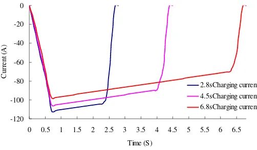
Using constant torque braking in braking process in, charging current curve as shown in figure 8. It can be seen from the figure, as the speed decreases, the battery current feedback will decreases with the rotating speed of the motor. The maximum charging current of battery feedback could not exceed the actual battery acceptable current considering the battery safety. Through braking torque control in different pedal displacement, the braking torque and pedal displacement can achieve synchronous increases with constant torque braking, which is the same as conventional hydraulic brake system that different pedal displacement corresponding to different braking torque, speed linear decline, and accord with the driver operation habit, convenient control.
Figure 8. Current change curve with constant torque braking
6. Conclusions
In the electric vehicle with configuration of regenerative braking system, mechanical braking and motor braking is exist at the same time, which is joint worked, braking time requirements for braking situation. Through the analysis of the electro-hydraulic brake process, studied braking time identification method based on braking pedal angle speed integral, and determined batteryacceptable charging current dynamically according to the braking time. Used variable proportional valve hydraulic distribution line to distribute braking force reasonably, with the current as the control object, by constant torque braking to realize electro-mechanical brake coordination control strategy. The test proved that the braking time recognition algorithm can identify the braking time correctly, braking energy feedback control strategy can run based on braking time effectively. The control strategy maximmize feedback braking energy, and give attention to brake safety and protection system.
Acknowledgements
This research was supported by the Zhejiang province public technology applied research project (2014C31017), and Natural science foundation of zhejiang university of technology (2013XZ008).
References
[1] Sanketh SS, Orkun K. Regenerative Braking Control Strategy for Hybrid and Electric Vehicles Using Artificial Neural Networks. Communications in Computer and Information Science. 2014; 459: 103-112.
[2] Gang Li, Xiaofeng Zhao, Dianzhong Wen, Yang Yu. Research on Silicon-based Planar Spiral Inductance Coil Based on Microelectromechanical System. TELKOMNIKA (Telecommunication Computing Electronics and Control), 2015; 13(4): 1127-1132.
[3] Yang YJ, Zhao H, Zhu MF. A Study on the Contol Strategy for Maximum Energy Recovery by Regenerative Graking in Electric Vehicles.Automotive Engineering. 2013; 35(2):105-110.
-120 -100 -80 -60 -40 -20 0
0 0.5 1 1.5 2 2.5 3 3.5 4 4.5 5 5.5 6 6.5
Time (S)
C
u
rr
en
t (A
)
[4] Zhang YC, Yu ZP, Xu L. A Study on the Strategy of Braking Force Distribution for the Hybrid Braking System in Electric Vehicles Based on Braking Intention. Automotive Engineering. 2009; 31(3): 24-249.
[5] Liu H, Wang WD, He J. Modeling and Simulation of the Regenerative Braking System in a HEV Based on Fuzzy Control.Automotive Engineering. 2012; 34(1):51-56.
[6] Ma QZ. Study on Regenerative Brake Control Algorithm Based on Braking Intention Identification. Chang Chun: Jilin University. 2013; 123-132.
[7] Ye M, Bai ZF, Cao BG. Energy recovery for battery electric vehicles. Proceedings of the Institution of Mechamical Engineers. Part D: Journal of Automobile Engineering. 2008; 222(10): 1827-1839. [8] Mohammad Saad Alam, Rakan C Chabaan. Realization of Hybrid-Electric Powertrain System for a
Three Wheeler Auto Taxi. Bulletin of Electrical Engineering and Informatics. 2012; 1(2): 131-138. [9] Zhou KK, Chen L, Pan CF. Electric Vehicle Regenerative Braking System Based on Constant
Current Control of Composite Power Sources.Journal of Mechanical Engineering. 2013; 49(20): 78-83.
[10] Tao Deng, Chunsong Lin, Bin Chen. Research on the Regenerative Braking Control Strategy Considering Battery/Motor/CVT Joint High Efficiency for CVT Hybrid Electric Vehicle. TELKOMNIKA Indonesian Journal of Electrical Engineering. 2014; 12(9): 6673-6681.
[11] E. Sheeba Percis, Manivannan S, Nalini A. Electric Vehicle as an Energy Storage for Grid Connected Solar Power System. International Journal of Power Electronics and Drive Systems (IJPEDS). 2015; 6(3): 567-575.
[12] Lian YF, Tian YT, Hu LL. A new braking force distribution strategy for electric vehicle based on regenerative braking strength continuity. Journal of Central South University. 2013; 20(12): 3481-3489.
[13] Zhou YP, Zhao H, Jiang H. Regenerative braking system for EV with fuzzy control based on particle swarm optimization. Journal of Hefei University of Technology (Natural Science). 2014; 37(7): 769-772.