ii
DESIGN AND DEVELOPMENT OF MINI VACUUM TUBE TESLA COIL (VTTC)
MOHD SHAH SOFFIAN BIN SOLAH
This report is submitted in partial fulfillment of the requirements for the award of Bachelor of Electronics Engineering (Industrial Electronics) With Honours
Faculty of Electronic and Computer Engineering Universiti Teknikal Malaysia Melaka
iii
“I hereby declare that this report is the result of my own work except for quotes as cited
in the references”
Signature :………
iv
“I hereby declare that I have read this report and in my opinion this report is sufficient in
terms of the scope and quality for the award of Bachelor of Electronic Engineering (Industrial Electronic) With Honours.”
Signature :………
v
vi
ACKNOWLEDGEMENT
Alhamdulillah, thanks to Allah because of his blessing, I manage to finish this
“Projek Sarjana Muda” in a good condition and sharp on time. I also would like to take
vii
ABSTRACT
viii
ABSTRAK
ix
CONTENTS
CHAPTER TITLE PAGES
PROJECT TITLE i
DECLARATION iii
DEDICATION v ACKNOWLEDMENT vi
ABSTRACT vii
CONTENTS ix
LIST OF TABLE xii
LIST OF FIGURES xiii
LIST OF ABBREVIATION xv
LIST OF APPENDICES xvi
I INTRODUCTION 1.1 Introduction of the Project 1 1.2 Objectives 1 1.3 Problem Statement 2 1.4 Scope 2
1.5 Methodology 3
II LITERATURE REVIEW
x
2.2 Applications 6
2.3 Building a Mini Tesla Coil 7
2.4 Baseboard 9
2.5 Capacitor 9
2.6 Spark Gap 9
2.7 Primary Coil 10
2.8 Secondary Coil 11
2.9 Toroid 12
2.10 Tuning 12
2.11 Flyback Transformer Used To Produce High Voltage 13
2.12 How it works 14
2.13 Practical Considerations 15
2.14 Construction 15
III METHODOLOGY
3.1 Introduction 17
3.2 Design Power Supply 12v, 10 ampere 18
3.3 Design Mini Vacuum Tube Tesla Coil 22
3.3.1 Brief theory of Operation 22
3.3.2 Circuit Description Schematic 23
3.3.3 Description of Major Components 24
3.3.3.1 A- LSl Secondary Coil 24
3.3.3.2 B- Output Terminal 25
3.3.3.3 C-LP1-Primary Coil 25
3.3.3.4 D-Coupling 26
3.3.3.5 E- SPK- Spark Gap Switch 26
3.3.3.6 F-C3-Primary Capacitor 26
3.3.3.7 G Chk1-Rf Choke 27
3.3.4 Assembly Step 27
xi
3.3.6 Special Steps 39
IV RESULT & DISCUSSION
4.1 Result 44
4.1.1 Secondary Tesla Coil 44
4.1.2 Complete Model of Tesla Coil 46
4.2 The Arc Spark 49
V DISCUSSION AND CONCLUSION
5.1 Discussion 50
5.2 Electrical Reception 51
5.3 In Fiction 54
5.4 Tesla Coil Effect 56
5.5 Conclusion 56
xii
LIST OF TABLE
NO TITLE PAGES
3.3 Component List for Power Supply 21
3.1 Electrical Parts 41
3.2 Sub Assemblies 41
3.3 Fabrication 42
xiii
LIST OF FIGURES
NO TITLE PAGES
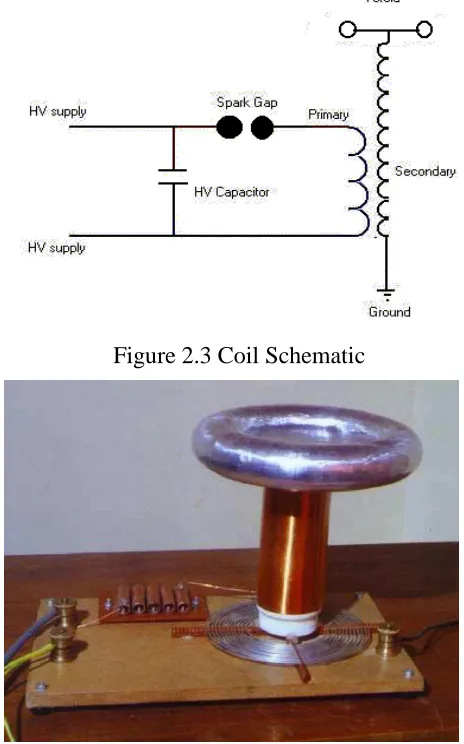
2.3 Coil Schematics 7
2.4 Finished Coil 7
2.5 The Oscillator Circuit 8
2.6 Flyback Transformer 14
3.1 Flow Chart Project Methodologies 17
3.2 Power Supply Circuit 20
3.3 Tesla Coil Schematic 23
3.4 Plans Schematic 28
3.5 Assemble Secondary Coil 29
3.6 Assemble Chokes 30
3.7 Fabricate the top and bottom base section 31
3.8 Fabricate plastics parts 32
3.9 Fabricate parts for sparks switch 33
3.9.1 Fabricate metal parts 34
3.9.2 Assemble primary coil section 35
3.9.3 Assemble Base Bottom Wiring Circuit 37
4.1 Secondary Tesla Coil 44
4.2 Toroid 45
4.3 Primary Coil of Tesla Coil 46
4.4 Complete Tesla Coil 46
4.5 Complete Model of Tesla Coil left view 47
xiv
4.7 Spark Gap of Tesla Coil 48
xv
LIST OF ABBREVIATION
FBT - Flyback Transformer DC - Direct Current
VTTC - Vacuum Tube Tesla Coil PCB - Printed Circuit Board TPI - Turn Per Inch
SCR - Silicon Controlled Rectifier HF - High Frequencies
xvi
LIST OF APPENDICES
NO TITLE PAGES
A Transistor 2N3055 Datasheet 59
1
CHAPTER I
INTRODUCTION
1.1 Introduction of the project
A Tesla coil is a high frequency resonant transformer. It differs from a conventional transformer in that the voltage and current relationships between the primary winding and secondary winding are independent of the winding turn’s ratios. A working apparatus basically consists of secondary and primary coil. It is obvious that the primary circuit is dominant, and turning the primary circuit via taps along the primary coil alters the frequency accordingly, however this relative fine-tuning of the primary circuit to the secondary is mandatory for proper operation. Force driving the secondary coil will produce hot spot and an interwinding breakdown along with other negative result. This mini Tesla Coil was originally designed to run using project basically to design the circuit for Wind source can be an excellent complement of electric power requirement.
1.2 Objectives
1.2.1 To study and develop a high voltage DC up to 30KV by using Neon (high
voltage) transformer
1.2.2 To produce arc using high voltage at the safe condition
1.2.3 To analyzed the arc sparking
1.2.4 To Design and Develop a Tesla Coil by using Neon (high voltage)
2
1.3 Problem Statement
Nowadays, so many type of Tesla Coil develop by others that use high voltage to produces arc (spark).The different with my project is develop Tesla Coil using basic application to produce arc (spark) by using Neon (high voltage) transformer.
1.4 Scope
This project is to develop Mini Vacuum Tube Tesla Coil by using Neon (high voltage) transformer to produced high voltage; low ampere from voltage input voltage 240AC and analyzed the output voltage and current from the arcs that Tesla Coil produced.
1.5 Methodology
Firstly, search a literature review to collect more information about this project. The literature review will take journal, report, internet and books as it reference. To design a Mini Vacuum Tube Tesla Coil (VTTC), the theory and all application about Tesla Coil circuit has been studies and understanding. Make a research about circuit theory and the characteristic of each component to redesign the Tesla Coil circuit. Later, some literature review will used to compare this project with previous experiment and related project for this title.
3
determine the sum of component and stage that the circuit required to get the right output voltage.
4
CHAPTER II
Literature review
A Tesla coil is a type of resonant transformer circuit invented by Serbian-American scientist Nikola Tesla around 1891. It is generally used to generate very high voltage, low current, and high frequency alternating current. A Tesla coil consists of two, or sometimes three, coupled resonant electric circuits. A Tesla coil is difficult to define, as Nikola Tesla experimented with a large variety of coils and configurations. Tesla used these coils to conduct innovative experiments in electrical lighting, fluorescence, x-rays, high frequency alternating current phenomena, electrotherapy, and wireless power for electric power transmission.
Early Tesla coil designs usually employed a high voltage power source, one or more high voltage capacitor, and a spark gap to excite the primary side of the Tesla coil system with periodic bursts of high frequency current. Later and higher power coil designs had the primary and secondary circuits tuned so that they resonated at the same frequency (typically, between 25 kHz and 2 MHz). These larger Tesla coil designs are used to create long electrical discharges.
5
power gas discharge lamps, common examples being the mercury vapor and sodium types used for street lighting. Although electronic igniters are available, Tesla's original spark gap design is much cheaper and has proven extremely reliable. A Tesla coil, named for its inventor Nikola Tesla, is a high-voltage resonant transformer that can be used to produce long electrical discharges.
To investigate the electrical realm of high-frequency and high-voltage, Tesla invented an apparatus that pushed the limits of electrical understanding. None of the circuit's typical components were unknown at the time, but its design and operation together achieved unique results not the least because of Tesla's masterful refinements in construction of key elements, most particularly of a special transformer, or coil, which is at the heart of the circuit's performance.
Such a device first appeared in Tesla's US patent No. 454,622 (1891), for use in new, more efficient lighting systems. In its basic form, the circuit calls for a power supply, a large capacitor, the coil (transformer) itself, and adjustable spark-gap electrodes.
2.1 Oscillators
6
To set his oscillator "ringing" Tesla employed sudden discharges, sparks, across an adjustable gap between two electrodes. Voltage on a capacitor builds until it reaches a level at which air in the gap breaks down as an insulator. (Precision screws set the gap clearance, so that a larger or smaller gap selects a larger or smaller breakdown voltage.) The initial impulse is very powerful all the energy stored over several microseconds is released in a rush, and that impulse is itself transformed to a somewhat higher voltage in passing from the primary coil windings to those of its secondary. This, of course, completes but a single cycle in the circuit's operation. The air gap restores itself as an insulator, and the capacitor begins to charge until it reaches a breakdown value once again. The whole process can repeat itself many thousand times per second.
The transformer's secondary is rather special, too, designed by Tesla to react quickly to a sudden energy spike and, most importantly, to concentrate voltage at one end as a standing wave. Its length is calculated so that wave crests, as they reach the end and are reflected back, meet and exactly reinforce the waves behind them. The net effect is a wave, a voltage peak, which appears to stand still.
2.2 Applications
If, as happened in practice, Tesla made an antenna of the high-voltage end of his secondary, it became a powerful radio transmitter. In fact, in the early decades of radio, most practicable radios utilized Tesla coils in their transmission antennas. Tesla himself used larger or smaller versions of his invention to investigate fluorescence, x-rays, radio, wireless power, biological effects, and even the electromagnetic nature of the earth and its atmosphere.
7
has become a commonplace in electronics, used to supply high voltage to the front of television picture tubes, in a form known as the flyback transformer.
2.3 Building a Mini Tesla Coil
[image:22.612.208.440.314.686.2]This mini Tesla Coil was originally designed to run using a previously built high voltage flyback circuit as a power supply. The circuit provided about 45watts at about 10kV. This means that there are limits to the size of arc that can be produced. My coil is capable of 4" arcs. Such a small coil provides a great talking point, and is small enough to be easily portable. Another point is that it is cheap to build.
Figure 2.3 Coil Schematic
8
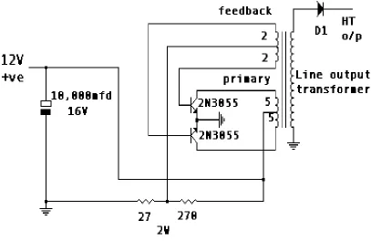
Figure 2.5 The oscillator circuit
9
2.4 Baseboard
Various materials can be used for the baseboard, provided that they are good insulators. The coil shown in the picture used varnished MDF. A good alternative would be acrylic sheet or polycarbonate.
2.5 Capacitor
The capacitor used in this particular coil needed a value of approximately 5nF at about 10-15kV, since used it with 8.3nF with appropriate adjustments to the primary coil tapping. There are various ways of obtaining these values. Whilst many coilers would use a string of higher value capacitors in series, it used an alternative approach initially, building my own from double sided printed circuit board. For the 8.3nF capacitor used an MMC, consisting of 12 x 100nF 1k5V rated Philips capacitors. If you go this route, then it is essential that you use the correct type of capacitors, namely foil polypropylene capacitors rated at the appropriate voltage and of the appropriate construction for high discharge rates. A number of sites have details of the construction of MMCs, read what they have to say before going this way, it will save you a lot of time, effort, money and frustration. Other approaches include making rolled polythene or salt water capacitors. Both these latter approaches can be messy, and they end up with very bulky components. Bleeder resistors should be placed across capacitors, these need to be high voltage types, they also need to be of high value, for example for an MMC 10M across each capacitor.
2.6 Spark Gap