Australian Journal of Basic and Applied Sciences
Journal home page
Corresponding Author: Anuar Mohamed Kassim, Universiti Teknikal Malaysia Melaka, Department of Mechatronic Engineering, Faculty of Electrical Engineering, Box.75200. Melaka. Malaysia.
(+606) 5552317; E-mail: [email protected]
Exploratory Study on Navigation System for Visually Impaired Person
1Anuar Mohamed Kassim, 1Ahmad Zaki Shukor, 1Chan Xin Zhi, 2Takashi Yasuno
1Universiti Teknikal Malaysia Melaka, Department of Mechatronic Engineering, Faculty of Electrical Engineering, Box. 75200. Melaka. Malaysia.
2The University of Tokushima, Graduate School of Advanced Technology and Science, 770-8506 Tokushima, Japan.
A R T I C L E I N F O A B S T R A C T
Background: Direction is arguably the most pressing concern for visually impaired person. Nevertheless, we lack a convenient navigation system to guide a visually impaired person using point to point direction to reach desired destination independently while walking on tactile paving. Accessibility of this navigation system must be convenient and simple for visually impaired people. In order to provide an efficient and user friendly assistive tool, it is proposed to design and develop a navigation system using Radio Frequency Identification (RFID) to guide the visually impaired walking on tactile paving. Path planning algorithm will be implemented in this project to give the shortest path and direction as a navigation guide for visually impaired people. This project will directly contribute to society by making available a convenient navigation system for visually impaired people for a better lifestyle.
© 2013 AENSI Publisher All rights reserved. To Cite This Article: Anuar Mohamed Kassim, Ahmad Zaki Shukor, Chan Xin Zhi, Takashi Yasuno., Exploratory Study on Navigation System for Visually Impaired Person. Aust. J. Basic & Appl. Sci., 7(14): 211-217, 2013
INTRODUCTION
World Health Organization (WHO) has reported global data on visual impairments back in 2010 where statistics of visual impaired and blindness shows 285 million people are estimated to be visually impaired worldwide. This amount includes 39 million blind people while 246 million have low vision. This shows that there are great numbers of people worldwide who have encountered vision loss including Malaysia citizens. Large amount of eye disease patient throughout the world cannot be just ignored based on data of eye prevalence stated above.
It has been decades since visually impaired people use white cane as their most basic and affordable assistive tool to detect obstacle and path surrounding them. Difficulties still occur when using white cane for visually impaired people as they are only able to detect path and obstacles from the front by swinging the white cane at the same time trying to feel the tip of the white cane that touches the ground. They do not receive enough information with only the tip of the white cane as feedback. Lack of aid signs built for visually impaired people seem to be one of the difficulties for them.
In this modern society, there are many types of assistive equipment, tools or robots developed by the motivated engineer or scientist worldwide to help the visually disabled people improve their quality of life as well as bring convenience into their daily life in terms of independency. The assistive equipment and tools developed are GuideCane (Borenstein and Ulrich, 1997), NavBelt (Shoval et al., 2003), Echolocation (Ifukube
et al., 1991), My 2nd Eye (Kassim et al., 2011) and others. Besides that, one of the developed assistive robots
for the blind is RoboCart (Kulyukin et al., 2005) which is the improvement of robotic shopping assistant for the blind (Gharpure et al., 2002) is designed to help the blind in shopping malls. Without the state of the art assistive technology, the visually impaired or the blind commonly rely on the conventional white cane to detect the surrounding obstacle and sense the road in front of them. Although the conventional white cane is not as convenient as the assistive tool but still the cane is at least affordable and important in their daily life.
otherwise they might be involved in hazardous situation such as falling into a drain or walking on a busy road. Thus, wireless voice navigation system may bring benefits for the blind where the navigation system assists the blind in point-to-point navigation by giving verbal direction, additionally the surrounding area or point of interest can be identified by a preset voice as well (Kassim et al., 2013). By integrating wireless technology system in the conventional assistive tools, it will greatly help the visually disabled people in their outdoor activities. In the present research, blind navigation is developed to assist the visually disabled for indoor and outdoor environment. Moreover, several wireless navigation systems for outdoor environment have been proposed or already exist in the market but the characteristics are similar with indoor navigation system yet integrated with different technologies (Kassim et al., 2012). The major wireless technologies are GPS, GPRS, GSM, Bluetooth and RFID technology.
Moreover, an assistive navigation system using both Bluetooth and RFID technology was researched in the study. A combination of RFID and Bluetooth reader modules in the control system were integrated in the conventional white cane, where the RFID reader reads the RFID-Tag to get the information of the surrounding area while the Bluetooth receiver receives zone coordinates of current location in a covered area from the Bluetooth-Track/dongle. Both received information are transformed into voice format by a sound control circuit embedded in the control board to notice/alert the user by voice (Ganz et al., 2010).
Meanwhile, University of Science and Technology of China proposed a system of navigation for the blind by providing information about their surrounding using RFID technology. The system comprises mobile phone, remote server RFID Tag as well as RFID Tag reader. In the study, the RFID Tags have been categorized into several types where information tag stores the road condition or information of current location while Cue Tag stores specific location (e.g. shop) whereas guidance tag stores information of hazardous conditions (i.e. junction, railway). The RFID Tag reader installed on the white cane connects wirelessly to mobile phone through Bluetooth interface (Ding et al., 2010). Mobile phone transforms the information from the Tag into voice format to navigate the blind by voice.
Besides that, the National Rehabilitation Centre for the Disable in Japan developed a navigation system composed by RFID Tag reader and a colour sensor build-in on the white cane (Shiizu et al., 2007). The system design to scan the particular colour tape on the ground to navigate the blind move in the desire path whereas the RFID Tag provide the information of surrounding area in voice. The navigation system integrated with vibrator and voice to notify or alert the blind. Although many navigation system had been developed in different types of wireless detection technologies, but they share the same goal which is assist the visually impaired or the blind move conveniently from one place to another.
A* search algorithm is one of the shortest path algorithm widely implemented to search for shortest route in a known map. A* algorithm is a type of search algorithm which search for least cost path from a start node in a graph to a target node optimizing a defined function (Ortin et al., 2010). Computation of shortest path in
dynamic networks is at the heart of the computational needs of transportation applications (Chabini and Shan 2002) which assist in most navigation system. Implementation of A* search algorithm is to provide visually impaired an ease to find the shortest route from current position to desired destination thus navigate them to their destination in shortest time possible.
MATERIAL AND METHOD
Electronic White Cane Construction:
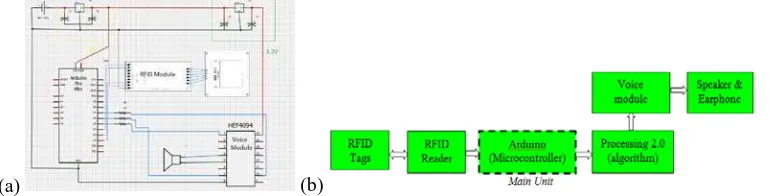
In order to transform a normal white cane into an electronic white cane, microcontroller is needed so that all the connected hardware is able to communicate with each other. In this project, RFID reader is used to read the RFID TAG and a voice module is included to play voice file to the user. The purpose of combination of RFID system and voice module is to play a particular voice file to user under a particular condition. The main hardware/modules used in this project are Arduino Uno R3 Microcontroller, MiFare High Frequency 13.56MHz RFID reader module and WTV020 voice module. Fig 1 (a) shows the illustration of the developed electronic white cane integrated with RFID.
(a) (b) (c)
Fig. 1: Illustration of developed electronic white cane (a) Electronic white cane designed (b) Speaker and
Earphone part (c) RFID reader and antenna part
RFID Detection System:
The design and development of tactile detection is to prevent deviation when the blind moving on the tactile paving. Verbal direction will be navigating the blind along the journey by simply swing the designed white cane near to the tactile pavement. The RFID Tag reader located on the bottom of white cane activates the Tag installed in the pavement to extract or receive the unique information. The received information transform into voice by control circuit board in the system to notify the blind about the information of location and direction. The RFID detection system is developed the design schematic diagram which is shown in Figure 2 (a). The pins assigned for modules connection are remain the same while two extra regulators are introduced in the final system due to the lack of suitable voltage supply which needed to power up the RFID module and voice module.
(a) (b)
Fig. 2: Illustration of electronic white cane circuit designed (a) Electronic part schematic design (b) Block
diagram of RFID navigation system.
From Figure 2 (a), voltage regulator L7805 is use to convert the input voltage from 9V battery or 12V DC supply to usable 5V for ARDUINO Pro Mini microcontroller. Furthermore, according to the specification of voice module, another voltage regulator LM1117T is needed in order to supply usable 3.3V to the board itself. From the block diagram shown in Figure 2 (b), the whole system consists of input part which is the RFID TAG reader, the controller part which composed by Arduino which process through shortest path algorithm by Processing 2.0 as well as the voice processor module and the output part is either earphone or speaker.
Shortest Path Search Algorithm:
In order to calculate shortest path from point initial node to goal node, shortest path A* search algorithm is implemented because it is noted for its performance and accuracy among researchers. A* search algorithm tends to find a least cost path from given initial node to goal node. Distance between adjacent nodes and initial node will be compared in order to determine the shortest distance taken to get to the second node. If second node has been set to be the node taken among other adjacent nodes, then initial node will be set to be the parent node of the second node. This means that initial node has now become a closed node that will not be used to search for the third node. Meanwhile, second node is now used as the reference node to determine the third node. Shortest distance from nodes to nodes will be compared until the shortest distance to reach goal node is determined. A* search algorithm implements heuristics (usually denoted ash n( )for a given noden) which is the estimated cost
from current node to goal node and past path function (usually denoted asg n( ) for a given noden) which is the
known distance from starting node to current node to calculate the evaluation function of nodef n( ) for a given
node
n
. Thus, the complete equation to determine the next node from current node is,( ) ( ) ( )
f n =g n +h n (1)
Earphone
Speaker Electronic white cane
RFID Antenna RFID Reader
generated will not be the smallest possible distance if overestimation occurs. Taxicab distance is used in this project to estimate the distance from starting node to goal node of heuristicsh n( ). Taxicab distance is the sum of absolute differences between two points in a Cartesian coordinates. The taxicab distance between nodenand nodemin a Cartesian coordinate is determined with the sum of absolute differences between nx−mx on x-axis
and absolute differences between ny−myon the y-axis. The complete equation to determine the taxicab
distance, dTaxicabbetween node
n
and nodem
is,| | | |
Taxicab x x y y
d = −n m + n −m (2)
Thus, heuristicsh n( )of nodenand nodemcan be estimated as,
( ) | x x| | y y|
h x = −n m + n −m (3)
A* search algorithm first searches the route that it is most likely to lead to goal node from initial node. It maintains a priority queue of nodes to be searched. This priority queue is known as open set because lower evaluation function of f n( ) for a given node
n
gives a higher priority. Node with the lowest f n( )is removed from a priority queue at each step of the algorithm. Neighbor nodes of a removed node within a priority queue will be updated with the latest value off n( )andg n( ). The algorithm continues to search for lower f n( )alongthe route value until goal node is reached and the queue is empty. The f n( )value of goal node is the final distance of the shortest path from initial node to goal node.
Pseudocode of Algorithm:
The pseudocode created for the A* algorithm in this project is as follow,function astar(start,goal) // initialize A* algorithm function from start node to goal node map[ ][ ] = {array of empty map} // Array map of navigated nodes closedset[ ][ ] = {evaluated nodes} // Array map of evaluated (already visited) nodes openset[ ][ ] = {start} // Array map of nodes to be evaluated (unvisited) nodes g[start] = 0 // cost of distance from starting node to current node h(start , goal) = abs(start1- goal1) + abs(start2 - goal2) // heuristic estimate distance from current to goal f[start] = g[start] + h(start, goal) // estimated total cost from start to goal f = g + h while (openset[ ][ ] != empty) //while openset not in empty state current = node in openset[ ][ ] that has the lowest f[ ] value // current node that contains lowest f value if current = goal // if goal node found to be same node as current node return path_found // path to goal has been found remove current from openset[ ][ ] // current node that becomes parent node is eliminated from open set map add current to closedset[ ][ ] // current node that has become parent node is added to close set map for each adjacent_nodes in adjacent_nodes(current) // Neighboring nodes of current node uncertain_g = g[current] + dist_between(current,adjacent_nodes) // calculated g value from current node // heuristics estimate distance from adjacent node to goal node h(adjacent_nodes, goal) = abs (adjacent_nodes1- goal1) + abs(adjacent_nodes - goal2) uncertain _f = uncertain_g + h(adjacent_nodes , goal) // calculate f value from current node if adjacent_nodes in closedset and uncertain _f >= f [adjacent_nodes] // whenever f value is not the lowest value continue // continue searching if adjacent_nodes not in openset or uncertain _f < f[adjacent_nodes] // if lowest value of f is found map[adjacent_nodes] = current // the adjacent node found with lowest f value is updated in map g[adjacent_nodes] = uncertain_g // the g value of the adjacent node is updated f[adjacent_nodes] = uncertain_f // the f value of the adjacent node is updated if adjacent_nodes not in openset // check adjacent avaibility in open set map add adjacent_nodes to openset // if not in open set map add adjacent node to open set map return path_not_found // return if path cannot be calculated
Whenever start and goal point is known, the algorithm will calculate the shortest path from the two points based on f = +g h. Pseudocode above is implemented in Java programming language with Processing 2.0 as its compiler. Start and goal point is selected with left mouse button while route is generated when any key on keyboard is pressed. Processing 2.0 is chosen as the compiler for its capability to interact with Arduino conveniently compared to other types of compiler.
A* Algorithm Implementation Using Processing 2.0:
(a) (b)
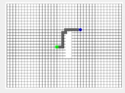
Fig. 3: Illustration of A* algorithm (a) Empty Map with wall on centre (b) Path (gray line) generated from Start
node (ellipse in blue) to Goal node (rectangle in green)
Estimated shortest path is generated successfully from start node to goal node shown in Fig 3. In order to implement the A* search algorithm in reality, RFID tags is used to indicate the start and goal nodes. Each RFID tags are programmed to have their own identification. Whenever the RFID antenna detects an RFID tag, it will show the detected RFID tag as start node (blue ellipse as shown in Fig 3 (a). User can then select the goal (green rectangle as shown in Fig 3 (b) he or she wants to go. After selection of destination is decided, shortest path route will be generated from start node to goal node. Voice guide will then guide user to walk node to node using simple direction guidance (e.g. forward, turn left, turn right, stop) following the path generated from start node to goal node.
RESULT AND DISCUSSION
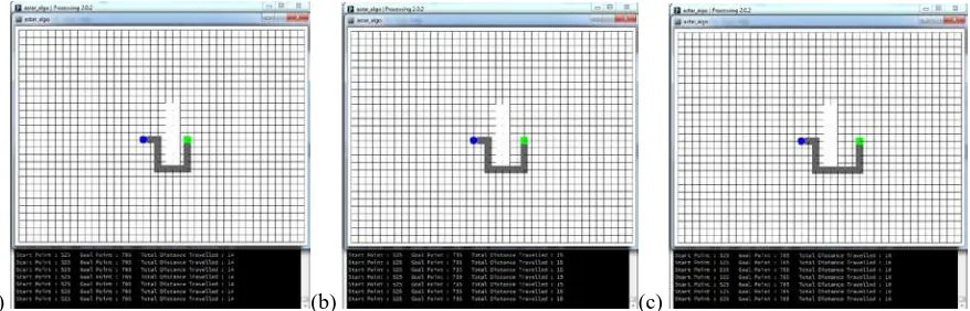
Fig 4 shows 3 different paths generated from same a start node but with a different goal node. The distance different between goal node in Fig 4 (a) and Fig 4 (b) is 1 while between Fig 4 (b) and Fig 4 (c) is 1 as well. As shown in Fig 4 (a), Fig 4 (b) and Fig 4 (c) the distance taken to travel on the path generated from start node to goal node are 14, 15 and 16 respectively. The path shows that A* algorithm implemented is able to generate shortest path with known start and goal node.
(a) (b) (c)
Fig. 4: Illustration of Start and Goal node (a) First path travelled (b) Second path travelled (c) Third path
travelled
Fig 4 is to compare the path generated if different goal node is changed. In order to integrate the algorithm with navigation system of visually impaired person, RFID tags are planted on the tactile paving to indicate as nodes on the map. A simple map with tactile paving is designed to test the function of the algorithm with RFID tags planted. Fig 5 (a) shows the map designed approximates the empty map in Fig 3 (a). Tactile paving is the rectangle shape with orange color while the white circle tags on the tactile paving is the RFID tags as shown in Fig 5 (a). When RFID antenna detected a RFID tag on the tactile paving, start node is shown as blue node on the virtual map as shown in Fig 5 (b).
(a) (b) (c)
Fig. 5: Illustration of Tactile paving and RFID experiment (a) Simple map of tactile paving with planted RFID
tags (b) Detect a RFID tag on tactile paving (c) Zooming in of RFID tag detected as blue node in virtual map
Goal node can then be chosen by user to generate the shortest path that will guide user to walk from start node (ellipse in blue) to goal node (rectangle in green) as shown in Fig 6. Route generated is then transfer to voice module to output the direction to navigate user. Voice module has been saved with 5 directions of sound which are forward, turn left, turn right, stop and warning. At this stage, only 5 directions of sound are used as navigation after shortest path is generated to follow the direction from start to goal node. When user start to walk from start node to the next node, voice module will output sound to speaker and earphone to indicate the direction of next node that user needs to follow from current node. After user successfully follows direction from start node to next node, next node is the current node for the user. Voice module is then output again the direction that user needs to follow in order to move from current node to next node. This action is repeated until user reaches goal node.
Fig. 6: Illustration of shortest path generated with implementation of RFID tags on tactile paving
Conclusion:
In conclusion, A* search algorithm is the shortest path algorithm chosen to implement in RFID navigation system for visually impaired person. The algorithm is implemented in Processing 2.0 as it is the Arduino compatible Java language compiler. Shortest path is generated when start node and goal node are known in an empty map created. RFID tags are then planted on tactile paving to test the communication between program written and the detection point of the RFID in the map. Detected RFID tag is shown as start node on the map and user is able to chose the desired goal node he or she wishes to go. Shortest route is then generated on the map to navigate user to from start node to goal node. Voice module starts function after shortest path is generated on the map. 5 directions of sound are the output to navigate user from start node to goal node.
In the future, a map of a size room of 12
×
14 square feet will be drawn and tactile paving will be arranged to form a route around the room with RFID tags planted on it. Shortest path algorithm will be implemented to generate shortest path from start node to goal node on the map of the room. Additional directions of sound will be saved in voice module to give more information for user the direction navigating.ACKNOWLEDGEMENT
This research was supported by grant from Universiti Teknikal Malaysia Melaka award no. GLuar/2013/FKE (1)/ G00018 and also technically support by the member from The University of Tokushima, Japan.
REFERENCES
Borenstein, J. and I. Ulrich, 1997. The GuideCane-a computerized travel aid for the active guidance of blind pedestrians. Proceedings of International Conference on Robotics and Automation, 2: 1283-1288.
White tag Tactile Paving
Chabini, I. and L. Shan, 2002. Adaptations of the A* algorithm for the computation of fastest paths in deterministic discrete-time dynamic networks. IEEE Transactions on Intelligent Transportation Systems, 3(1): 60-74.
Ding, B., H. Yuan, L. Jiang and X. Zang, 2013. The Research on Blind Navigation System Based on RFID. International Conference on Wireless Communications, Networking and Mobile Computing, pp: 2058-2061.
Ganz, A., S.R. Gandhi, C. Wilson and G. Mullett, 2010. INSIGHT: RFID and Bluetooth enabled automated space for the blind and visually impaired. International Conference of the IEEE Engineering in Medicine and Biology Societ, pp: 331-4.
Gharpure, C., V. Kulyukin and A. Kutiyanawala, 2006. A Robotic Shopping Assistant for the Blind : A Pilot Study in a Supermarket. Proceedings of the Third International Conference on Ubiquitous Intelligence and Computing, pp: 51-60.
Ifukube, T., T. Sasaki and C. Peng, 1991. A blind mobility aid modeled after echolocation of bats. IEEE Transactions on Biomedical Engineering, 38(5): 461-465.
Kassim, A.M., H.I. Jaafar, M.A. Azam, N. Abas and T. Yasuno, 2013. and Technology (ICSET), pp: 258-262.
Kassim, A.M., H.I. Jaafar, M.A. Azam, N. Abas and T. Yasuno, 2013. System Engineering and Technology (ICSET), pp: 281-284.
Kassim, A.M., M.H. Jamaluddin, M.R. Yaacob, N.S.N. Anwar and Z.M. Sani, 2011. Design and Development of MY 2nd EYE for Visually Impaired Person. Procedings of IEEE Symposium on Industrial Electronics and Applications (ISIEA2011), pp: 700-703.
Kassim, A.M., M.S. Jamri, M.S.M. Aras, M.Z.A. Rashid and M.R. Yaacob, 2012. Design and development of obstacle detection and warning device for above abdomen level. Proceedings of 12th International Conference on Control, Automation and Systems (ICCAS), pp: 410-413.
Kulyukin, V., C. Gharpure and J. Nicholson, 2005. RoboCart: toward robot-assisted navigation of grocery stores by the visually impaired. 2005 IEEE/RSJ International Conference on Intelligent Robots and Systems, pp: 2845-2850.
Ortin, J., P. Garcia, F. Gutierrez and A. Valdovinos, 2010. A* Based Algorithm for Reduced Complexity ML Decoding of Tailbiting Codes. IEEE Communications Letters, 14(9): 854-856.
Shiizu, Y., Y. Hirahara, K. Yanashima and K. Magatani, 2007. The development of a white cane which navigates the visually impaired. International Conference of the IEEE Engineering in Medicine and Biology Society, pp: 5005-5008.