UNIVERSITI TEKNIKAL MALAYSIA MELAKA
DESIGN AND DEVELOPMENT OF 3-DOF MOTION PLATFORM
FOR VEHICLE SIMULATOR
This report submitted in accordance with requirement of the UniversitiTeknikal Malaysia Melaka (UTeM) for the Bachelor Degree of Mechanical Engineering
(Automotive) with Honours.
By
ONG CHING KEAT
SUPERVISOR DECLARATION
I hereby declare that I have read this report and in my opinion, this report is sufficient in terms of scope and quality for the award of the degree of Bachelor of Mechanical Engineering (Automotive)
Signature: Signature:
--- ---
Supervisor Name: Second Supervisor Name:
MR. FAUZI BIN AHMAD MR.
WAN MOHD ZAILIMI
BIN WAN ABDULLAH @
ZAKARIA
Date: Date:
DECLARATION
I hereby declare that this report entitled “Design and development of 3-DOF motion platform for vehicle simulator” is a result of my own research except as cited in the references.
Signature : ………
Name : ONG CHING KEAT
DEDICATION
i ACKNOWLEDGEMENT
I would like to use this chance to thank a lot of people who helping and teaching me while going through this Final Year Project or PSM study.
First of all, I am indeed grateful to my host university which is University Teknikal Malaysia Melaka (UTeM) for giving me this opportunity to carry out a two semester or one year final year project which will surely improve my self at many aspect such as knowledge, thinking and communication before entering the real working environment. I am sure that all the knowledge that I gain from the study will help me in accomplish my tasks for in the future engineering world. I am looking forward to further study in my beloved university.
Secondly, I would like to say thank you to my PSM supervisor and my hero Mr. Fauzi bin Ahmad for his patience, guidance and kindness. He provided many useful ideas, suggestions and examples to me on how to carry out my tasks or works effectively. Besides that, he also had the hard work to teach and guide me on a lot of MATLAB/Simulink software knowledge and skills. Furthermore, he will keep encourage me with word of caring and kindness to reduce my pressure at the time not even facing the tasks of PSM study but also others subject tasks. For me, he is the one of the caring and greatest lecturers that I have ever met in my study life.
Lastly, I would like to thank all the university staff and all my course mates who are also under going their PSM study for their cooperation and contributions. We always share information among each other in order to make things done. We are able to communicate well with each other and discussed together happily.
ii ABSTRACT
iii ABSTRAK
v
4.0 CHAPTER 4: SLIDER CRANK AND STEPPER MOTOR MECHANISMS 31
4.1 Introduction 31
4.2 Kinematic Slider Crank 31-32
4.3 Dynamic Slider Crank 33-34
4.4 Stepper Motor 34-37
4.5 Description of Simulation Model of Slider Crank 37 4.6 Description of Simulation Model of Stepper Motor 38-39
4.7 Conclusion 39
5.0 CHAPTER 5: 3-DOF MOTION PLATFORM 40
vi 6.4 Simulation Analysis and Performance Evaluation of the 3-DOF Motion
Platform with 7-DOF Full Vehicle Ride Model 48
6.5 Pitch Mode Bump Test 49-50
6.6 Roll Mode Bump Test 50-52
6.7 Conclusion 52
7.0 CONCLUSION AND RECOMMENDATION 53
7.1 Conclusion 53-54
7.2 Recommendation for Future Works and Problem Encountered 54
8.0 REFERENCES 55-58
vii
viii
Figure 29: Simulation Model of Stepper Motor 38
Figure 30: Actuator Model Combination between Stepper Motor and Slider Crank 39
Figure 31: The Direction of Force at Each Corner of the 3-DOF motion platform 40
Figure 32: Simulation Model of 3-DOF Motion Platform 42
Figure 33: Subsystems for Each Type of Motions 43
Figure 34: Model of Platform Vertical Displacement 43
Figure 35: Model of Platform Pitch Rate 44
Figure 36: Model of Platform Roll Rate 44
Figure 37: Controlled Structure of 3-DOF Motion Platform 45
Figure 38: Body Displacement 49
Figure 39: Pitch Angle 50
Figure 40: Body Displacement 51
Figure 41: Pitch Angle 51
ix LIST OF SYMBOLS
Ffl = suspension force at front-left corner
Ffr = suspension force at front-right corner
Frl = suspension forceat rear-left corner
Frr = suspension forceat rear-right corner
ms = sprung mass weight
�̈s = sprung mass acceleration at body centre of gravity
Fsfl = front left suspension spring force
Fsfr = front right suspension spring force
Fsrl = rear left suspension spring force
Fsrr = rear right suspension spring force
Fdfl = front left suspension damping force
Fdfr = front right suspension damping force
Fdrl = rear left suspension damping force
Fdrr = rear right suspension damping force
Ksfl = front left suspension spring stiffness
Ksfr = front right suspension spring stiffness
Ksrl = rear left suspension spring stiffness
Ksrr = rear right suspension spring stiffness
Csfl = front left suspension damping constant
Csfr = front right suspension damping constant
Csrl = rear left suspension damping constant
Csrr = rear right suspension damping constant
Zufl = front left unsprung mass vertical displacement
Zufr = front right unsprung mass vertical displacement
Zurl = rear left unsprung mass vertical displacement
Zurr = rear right unsprung mass vertical displacement �̇Rufl = front left unsprung mass velocity
�̇Rufr = front right unsprung mass velocity
�̇Rurl = rear left unsprung mass velocity
�̇Rurr = rear right unsprung mass velocity
a = distance between vehicle front to the centre of gravity of sprung mass
x
θ = pitch angle at body centre of gravity
φ = roll angle at body centre of gravity
Zs = sprung mass vertical displacement at body centre of gravity
Zsfl = front left sprung mass vertical displacement
Zsfr = front right sprung mass vertical displacement
Zsrl = rear left sprung mass vertical displacement Zsrr = rear right sprung mass vertical displacement �̇ = pitch rate at the body centre of gravity
�̇s = sprung mass vertical velocity at body centre of gravity
Ksf = front suspension spring stiffness
Ksr = rear suspension spring stiffness
Csf =front suspension damping constant
Csr = rear suspension damping constant
�̈ = pitch acceleration at the body centre of gravity �̈ = roll acceleration at the body centre of gravity
Iyy = pitch axis moment of inertia
Iyy = pitch axis moment of inertia
w = track width of sprung mass
�̈ufl = front left unsprung mass vertical acceleration �̈ufr = front right unsprung mass vertical acceleration �̈url = rear left unsprung mass vertical acceleration �̈urr = rear right unsprung mass vertical acceleration
1 CHAPTER 1
INTRODUCTION
1.1 Overview
Driving simulators are often used in educational and research purposes. Driving simulators’ capability in producing a virtual driving environment resembling real driving condition can be used to train novice drivers before they are exposed to the real world. (Kasim, 2004). Besides, driving simulators are important in data collection for road safety research, human factor study, vehicle system development and also traffic control device development. These allow designers, engineers as well as ergonomists to bypass the design and development process of detailed mock-ups of the automobile interiors for human factor and vehicle performance studies.
A driving simulators range in complexity, capability and can be classified into 3 major groups that are high, medium and low-level driving simulator. The National Advanced Driving Simulator NADS in IOWA, USA and the Toyota Driving simulator in Japan which started its operation on Nov 2007 are all the examples of high level simulator. These high level simulators have sophisticated systems such as a dome with 360 degree projection screen for virtual environment generation. They are also equipped with a full vehicle cab and a large motion platform which can mimic the driving conditions. On the opposite, low level simulators can be relatively simple which only require personal computer or graphical work station, monitor and a simple cab and driving controls. Between these two extremes is the mid-level driving simulator. Mid-level driving simulators can have adequate fidelity, validity and realism; yet affordable compared to the high-level driving simulator. With proper configuration and harmonization of the visual, motion and cues, they can perform a wide range of driving scenarios and tasks.
2 vehicle ride model, modeling a kinematics slider crank which will combine with modeling of stepper motor that act as an actuator for the slide crank. Besides that, the research also includes the study of PID controller and finally designing a control system for the motion platform.
Figure 1: Classification of driving simulators
3 1.2 Problem Statement
Road safety has always been a major concern for the Malaysian Government. The rapid increases in motor vehicle ownership in combination with the relatively young age of the populations and wide mix of vehicle types in the recent years have resulted in a significant increase of road safety problems. According to Malaysia Institute of Road Safety research (MIROS).
In Malaysia the number of road accidents per 1000 population is gradually increase from 10.8 to 12.8 cases (18.5%) in year 2000 until 2006. (Wong et al., 2004) Based on statistics, there are fourteen factors of road accident occurred, where the common factors are speeding (32.8%), careless driving (28.2%) and careless overtaking (15.1%). Other factors are tailgating (driving too closely behind another vehicle) (3.8%) and road condition (3%). It showed that the driver’s behaviour is the main cause of road accidents, contributing to 76.1% of all the causes of road accidents. (Ahmad, et al., 2009).Many action had been taken by government to overcome this problem such as road maintenance, building new roads, reactive action and proactive action. Consider from many aspects, the best way to reduce such problem is still the development of the driving simulator. Therefore, this project is proposed to design a vehicle simulator which will help these people improve their driving skill before driving on the real road.
Overalls, the vehicle simulator have a motion platform which is the combination of slider crank, stepper motor and parallel platform. Each corner of platform is supported by a slider crank leg and all totally is four legs. Stepper motor is use as an actuator to actuate each slider crank so that the platform can move at 3-DOF motion that is pitch motion, roll motion and vertical motion. Finally, design a control system for the motion platform.
4 1.3 Background of the Study
Vehicle simulation can be defined as the representation of vehicle and system dynamics characteristics with varying degrees of realism for research, design, training or entertainment purpose. (Ho Bang, 2007). Development of system modeling and simulation module is an important issue for effective operation including simulator subsystem. In addition, we have to implement a dynamics modeling which have robustness in the presence of uncertainty. Generally, there are differences between real systems and mathematical modeling. Robust stability in the presence of uncertainty is an important issue in control system analysis and has attracted considerable interests. And the so-called performance such as tracking of the reference input and satisfying of specification is another significant problem. Deriving a dynamic system modeling satisfying these objectives are very difficult because of the tradeoffs between complexity and performance of simulation in procedure of real implementation.
1.4 Project Objective
The main objective of this study is to design and development of 3-DOF motion platform for vehicle dynamic simulator by using CAD software or MATLAB/Simulink software. 3-DOF means the motion platform will have pitch motion, roll motion and vertical motion. Besides, fabricate and to evaluate the motion platform performance is also the primary objective of this study.
1.5 Project Scope
• 7-DOF full vehicle ride model derivation and modeling in MATLAB/ Simulink software.
• Verification of the 7-DOF full vehicle ride model with Carsimed software.
• Modeling of 3-DOF motion platform.
• Modeling and verification of dynamics and kinematics slider crank.
• Modeling and verification of stepper motor.
• Design the inner force tracking control of slider crank and motor.
5 1.6 Research Planning
Semester Activity
PSM1 • Searching for information on title
• Doing literature review about the title
• Study methodology to solve the problem
• Decide the behaviour of the slider crank
• Derive the equation of motion for slider crank, stepper motor and 7-DOF full vehicle model, 3-DOF motion platform
• PSM1 report preparation
• Submission of report
PSM2 • Modeling of slider crank in Matlab simulink
• Modeling of stepper motor in Matlab simulink
• Modeling of 7-DOF full vehicle ride model
• Validation of 7-DOF full vehicle ride model with carsimed software
• Modeling of 3-DOF motion platform
• Design control system for motion platform
• Analysis and validation of the motion platform
• Conclusion of PSM
• PSM 2 report preparation
6 1.7 Methodology
The motion platform for driving simulator is a mechatronic equipment that is capable of giving the realistic feeling of a actual vehicle to the drivers. This is a research that involves multidisciplinary engineering skills. It is divided into 3 major parts which is the control system design and simulation, motion platform mechanism design and fabrication, and finally the integration of both control and actual model. In the stage of control design and simulation, all the system should be modelled first such as vehicle model and motion platform so that the control strategy can be design.
First of all, the study begins with the literature review on the 7-DOF full vehicle ride model analysis. Then, the derivation equation of the 7-DOF full vehicle ride model is modeling in MATLAB/Simulink software. After that the full vehicle model is verified with vehicle dynamic simulation software namely as CarSimEd under the same input parameters as an model validation.
The second step of the study will be following with the derivation equation of the slider crank mechanism. The derivation equation wills then modeling in the same MATLAB/Simulink software too and verified it. After that, the studies proceed with the modeling and verification of the stepper motor. Stepper motor will be use as the actuator to actuate the slider crank that located at the four corner of the motion platform. Therefore, both modeling will be combining after each of their verification.
7 1.8 Methodology Flow Chart
The methodology flow chart will show the flow method that I will used in this study and explained the method step by step form literature review until fabriction.
8 CHAPTER 2
LITERATURE REVIEW
2.1 Introduction
This chapter will discuss the literature review about the background information of the study so that the reader can easily understand the research background. The first parts will provide some of the fundamental ideas and equipment that involves in the development of the vehicle simulator. Besides, it also includes some fundamental knowledge about the parts that use for the study in motion platform such as stepper motor, slider crank. This chapter also conclude some research method and research result that other researcher had done at the past. The research and development on vehicle driving simulator had become more and more popular among the engineering researcher and developer.
2.1.1 Type of Driving Simulator in Used
There are several types of driving simulator that used in our world now that are the Daimler which is Benz driving simulator, National Advanced Driving Simulator owned by the National Highway Traffic safety Administration (NHTSA) and the Toyota Driving Simulator which owned by Toyota Motor Cooperation (TMC) ( Chiew et al.,2008).
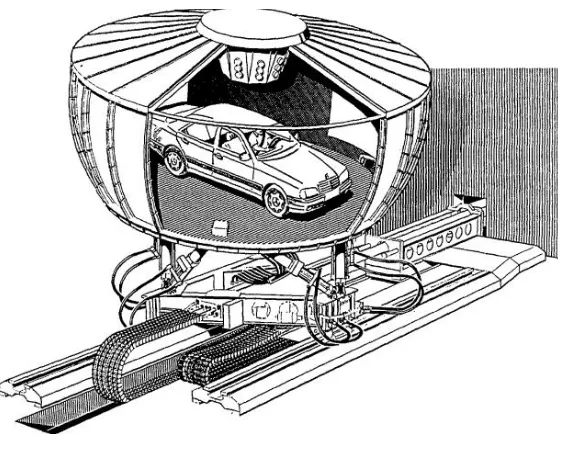
2.1.2 The Daimler – Benz Driving Simulator
Driving simulators are developed throughout the world for studies and analysis of human behaviour, vehicle performance as well as road safety research. The Daimler Chrysler has been one of the earliest automobile manufacturers that uses driving simulators in vehicle development process compared to any other car manufacturers. The concept was founded in 1980 and the first driving simulator was constructed in 1983 and put into operation in October 1984. It consists of a projection system that simulates the virtual environment,
9 .
Figure 4: The Daimler
2.1.3 National Advanced Driving Simulator
Another well-known driving simulator is the National Advanced Driving Simulator (NADS), which was started in 1992 and completed in 2001. It was built at the University of
IOWA and owned by the National Highway Traffic safety Administration (NHTSA) which was claimed to be the most advanced driving simulator in the world.
10 2.1.4 Toyota Driving Simulator
Recently in November 2007, the Toyota Motor Corporation (TMC) announced that it has developed a world-class driving simulator located at Toyota Motor Corporation's Higashifuji Technical Center in Susono City, Shizuoka Prefecture, Japan. The sole purpose of the driving simulation development was to conduct analysis of driving characteristics and development of active safety technology, and to verify the effectiveness of active safety technology.
Figure 6: Toyota Driving Simulator
2.1.5 Square 3-DOF Motion Platform