“I hereby declare that I have read through this report entitle “Proposed Metal-Oxide Surge Arrester Model to Improve Lightning Protection” and found that it has comply the partial fulfillment for awarding the degree of Bachelor of Electrical Engineering (Industrial Power)”
Signature : ...
Supervisor’s Name : En. Zikri Abadi Bin Baharuddin..
ii
PROPOSED A METAL-OXIDE SURGE ARRESTER MODEL TO IMPROVE LIGHTNING PROTECTION
LOW SIEW YI
This report is submitted in partial fulfillment of requirement for the degree of bachelor in electrical engineering (Industry Power)
Faculty of Electrical Engineering
UNIVERSITY TECHNICAL MALAYSIA MELAKA
2012
iii
I declare that this report entitle “Proposed Metal-Oxide Surge Arrester Model to Improve Lightning Protection” is the result of my own research except as cited in the references. The report has not been accepted for any degree and is not concurrently submitted in candidature of any other degree.
Signature : ...
Name : ...LOW SIEW YI...
iv
v
ACKNOWLEDGEMENT
In preparing this report, I was in contact with many people. They have contributed towards my understanding and thought. In particular, I wish to express my sincere appreciation and gratitude to my final year project supervisor, Encik Zikri Abadi Bin Baharudin for giving me the opportunity to have my final year project under his supervision. He willingness to assist me through his guidance, encouragement, advices, and support has been a great motivation for me to do my final year project.
I would also like to thank Puan Junainah Bt Sardi and Encik Mohd Khairi Bin Mohd Zambri for the assistance towards the successful completion of this project
vi
ABSTRACT
vii
ABSTRAK
Kilat merupakan faktor utama yang menyebabkan voltan lampau dan kegagalan pada electrik sistem. Konduktor kilat adalah alat perlindungan yang digunakan untuk menentang kilat. Model. Kajian ini akan menyiasat keberkesanan
daripada konduktor kilat yang baru
viii
TABLE OF CONTENT
CHAPTER TITLE PAGE
ACKNOWLEDGEMENT v
ABSTRACT vi
ABSTRAK vii
TABLE OF CONTENTS viii
LIST OF TABLES xi
LIST OF FIGURES xiii
LIST OF ABBREVIATIONS xvi
LIST OF SYMBOL xvii
LIST OF APPENDIX xviii
1 INTRODUCTION 1
1.1 Project Statement 1
1.2 Problem Objective 1
1.3 Scope of Works 2
1.4 Thesis Outlines 2
2 LITERATURE REVIEW 4
2.1 System Overvoltage 4
2.2 Lightning 5
2.3 Formation of Lightning 8
2.4 Standard Surge Testing Waveform 10
2.4.1 Detail Specification of Combination 11 waveform
2.4.1.1 Open-circuit 1.2/50µs Voltage Waveform 11 2.4.1.2 Short-circuit 8/20µs Current Waveform 11
2.5 Surge Arrester 12
2.5.1 Surge Arrester Type 13
ix
2.5.3 Fundamental of Metal Oxide Varistor 15 Technology
2.5.4 Fundamental of Metal Oxide Surge Arrester 16 Protection Theory
2.5.5 Type of Surge Arrester 17
2.5.6 Selection of Surge Arrester Rating 18
3 METHODOLOGY 19
3.1 Introduction 19
3.2 Literature Review 21
3.3 Modeling 21
3.3.1 Introduction to PSCAD 21
3.3.2 Lightning Stroke Modeling 22 3.3.3 Design and Modeling Surge Arrester 23 3.3.3.1 IEEE Surge Arrester Model 24 3.3.3.2 Pinceti Surge Arrester Model 25 3.3.3.3 Proposed Surge Arrester Model 26
4 RESULT 28
4.1 Result and Verified Process of Lightning Model 28 4.2 Result for Surge Arrester Model 30
4.2.1 IEEE Surge Arrester Model 32
4.2.2 Pinceti Surge Arrester Model 37 4.2.3 The Proposed Surge Arrester 42
5 ANALYSIS AND DISSCUSSION 47
5.1 Residual Voltage 49
5.2 Front time and tail time of current waveform 51 5.3 Front time and tail time of voltage waveform 53
5.4 Cost 56
6 CONCLUSION AND RECOMMADATION 57
6.1 Conclusion 57
x
REFERENCES 62
xi
LIST OF TABLES
TABLE TOPIC PAGE
2.1 The advantages and disadvantages of each type of 14
surge arrester
2.2 Type of surge arrester model 17
3.1 Equation and parameter value of IEEE surge arrester 24 model
3.2 Equation and parameter value of Pinceti model 25 3.3 Equation and parameter value of Proposed surge 27
arrester model
4.1 Comparison between simulation result and standard 29 4.2 V-I characteristic for A0 and A1 of IEEE model 32 4.3 Peak residual voltage and 5kA 8/20µs current impulse 33
for IEEE model
4.4 Peak residual voltage and 10kA 8/20µs current impulse 34 for IEEE model
4.5 Peak residual voltage and 20kA 8/20µs current impulse 35 for IEEE model
4.5 Peak residual voltage and 40kA 8/20µs current impulse 36 for IEEE model
4.6 V-I characteristic for A0 and A1 of Pinceti model 37 4.7 Peak residual voltage and 5kA 8/20µs current impulse 38
for Pinceti model
4.8 Peak residual voltage and 10kA 8/20µs current impulse 39 for Pinceti model
4.9 Peak residual voltage and 20kA 8/20µs current impulse 40 for Pinceti model
4.10 Peak residual voltage and 40kA 8/20µs current impulse 41 for proposed model
xii
4.12 Peak residual voltage and 5kA 8/20µs current impulse 43 for proposed model
4.13 Peak residual voltage and 10kA 8/20µs current impulse 44 for proposed model
4.14 Peak residual voltage and 20kA 8/20µs current impulse 45 for proposed model
4.15 Peak residual voltage and 40kA 8/20µs current impulse 46 for proposed model
5.1 Residual voltage and relative error for each model 49 5.2 Front time and Tail time relative error when inject 51
8/20µs current impulse with peak amplitude of 5kA to each model (current waveform)
5.3 Front time and Tail time relative error when inject 51 8/20µs current impulse with peak amplitude of 10kA to each model (current waveform)
5.4 Front time and Tail time relative error when inject 52 8/20µs current impulse with peak amplitude of 20kA to each model (current waveform)
5.5 Front time and Tail time relative error when inject 52 8/20µs current impulse with peak amplitude of 40kA to each model (current waveform)
5.6 Front time and Tail time relative error when inject 53 8/20µs current impulse with peak amplitude of 5kA to each model (voltage waveform)
5.7 Front time and Tail time relative error when inject 54 8/20µs current impulse with peak amplitude of 10kA to each model (voltage waveform)
5.8 Front time and Tail time relative error when inject 54 8/20µs current impulse with peak amplitude of 20kA to each model (voltage waveform)
xiii
LIST OF FIGURES
FIGURE TOPIC PAGE
2.1 Type of overvoltage 4
2.2 Number of days with thunderstorm,Td in Malaysia 5 2.3 Cloud-to-ground lightning downward negative 6
lightning
2.4 Cloud-to-ground lightning downward positive 6 lightning
2.5 Ground-to-cloud lightning upward negative 6
lightning
2.6 Ground-to-cloud lightning upward positive 6
lightning
2.7 Formation of lightning 8
2.8 Return stroke initiation and propagation 9 2.9 Combination wave open-circuit 1.2/50µs voltage 10 2.10 Combination wave short-circuit 8/20µs current 10 2.11 Voltage and overvoltage in high voltage electrical power 12
system
2.12 V-I characteristic of MOV 17
2.13 Under normal condition 16
2.14 Under overvoltage condition 16
3.1 Flow diagram of final year project 20
3.2 The developed lightning stroke model in PSCAD 22
3.3 IEEE surge arrester model 24
3.4 Pinceti surge arrester model 25
3.5 Propose surge arrester model 27
4.1 Lightning double exponential waveform generate in 28 PSCAD
xiv
4.4 Inject lightning current to proposed surge arrester 31 Model
4.5 The V-I characteristic for non-linear resistor of IEEE 32 model
4.6 Residual voltage of IEEE model for 5 kA 8/20µs 33 current impulse
4.7 IEEE model 5kA 8/20µs current impulse 33
4.8 Residual voltage of IEEE model for 10 kA 8/20µs 34 current impulse
4.9 IEEE model 10 kA 8/20µs current impulse 34
4.10 Residual voltage of IEEE model for 20 kA 8/20µs 35 current impulse
4.11 IEEE model 20kA 8/20µs current impulse 35
4.12 Residual voltage of IEEE model for 40 kA 8/20µs 36 current impulse
4.13 IEEE model 40kA 8/20µs current impulse 36
4.14 The V-I characteristic for non-linear resistor of Pinceti 37 model
4.15 Residual voltage of Pinceti model for 5 kA 8/20µs 38 current impulse
4.16 Pinceti model 5kA 8/20µs current impulse 38 4.17 Residual voltage of Pinceti model for 10 kA 8/20µs 39
current impulse
4.18 Pinceti model 10 kA 8/20µs current impulse 39 4.19 Residual voltage of Pinceti model for 20 kA 8/20µs 40
current impulse
4.20 Pinceti model 20kA 8/20µs current impulse 40 4.21 Residual voltage of Pinceti model for 40 kA 8/20µs 41
current impulse
4.22 Pinceti model 40kA 8/20µs current impulse 41 4.23 The V-I characteristic for non-linear resistor of 42
proposed model
xv
4.25 Proposed model 5kA 8/20µs current impulse 43 4.26 Residual voltage of proposed model for 10 kA 8/20µs 44
current impulse
4.27 Proposed model 10 kA 8/20µs current impulse 44 4.28 Residual voltage of proposed model for 20 kA 8/20µs 45
current impulse
4.29 Proposed model 20kA 8/20µs current impulse 45 4.30 Residual voltage of proposed model for 40 kA 8/20µs 46
current impulse
xvi
LIST OF ABBREVIATIONS
AC - Alternating Current DC - Direct current FYP - Final Year Project
PSCAD - Power system computer Aided Design software IEE - The Institution of Electrical Engineers
IEEE - Institute of Electrical and Electronic Engineers IEC - International Electrotechnical Commission MCOV - Maximum continues operating voltage MOV - Metal Oxide Surge Arresters
xvii
LIST OF SYMBOLS
µF - micro-Farad µH - micro-Hendry µs - micro-second A - Ampere
Ng - Ground Flash Density per Kilometer2 per year kA - kilo-Ampere
xviii
LIST OF APPENDIX
APPENDIX TOPIC PAGE
CHAPTER 1
INTRODUCTION
1.1 Problem Statement
According to Malaysian Meteorological Services Department, most state of Malaysia has a number of days with thunderstorm, Td more than 100[1]. The lightning
may cause serious consequence for the operating, maintaining and designing of the
electrical power system as well as protective device like surge arrester. For example,
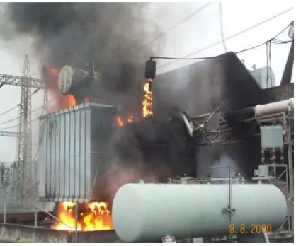
lightning can cause backflashover and induced overvoltages generate surge voltage that
[image:19.595.220.429.443.617.2]can cause damage to substation or power plant equipment as shown in Figure 1.1.
Figure 1.1 Damage to the transformer at TNB substation
Therefore, it is very important to investigate and propose some idea for improve
the lightning protection scheme in electrical power system. This can be done by proposed
a new surge arrester model, simulate using PSCAD. An accurate surge arrester model will
increase the lightning protective level of the electric power system.
2
Objective of this project are as follows:-
i. To design and develop a surge arrester model using PSCAD software.
ii. To develop IEEE and Pinceti metal-oxide surge arrester model using PSCAD software.
iii. To develop the lightning stroke using PSCAD software.
iv. To evaluate the effectiveness of the metal-oxide surge arrester model by comparing with others two common surge arrester model.
1.3 Scope of Work:
Scopes of this project are as follow:-
i. This project only concern on surge arrester lightning protection performance. ii. The surge arrester model is design based on 132kV electrical power system.
iii. The lightning current waveshape of 8/20µs with peak amplitude of 5kA, 10kA, 20kA and 40kA were used to represent lightning strike.
1.4 Thesis Outlines
This report is divided into six chapters. Basically, some theory and literature review, introduction, methodology, simulation result, comparison of result, analysis and discussion and conclusion were included in these six chapter.
Chapter 1 includes the project objective, problem statement, scope of work and thesis outlines. Continue by Chapter 2 presents the literature review on this project such as system overvoltage, phenomena of lightning, formation of lightning, fundamental of surge arrester, type of surge arrester and surge arrester parameter.
3
Chapter 4 includes the result and data. In this chapter, 8/20µs lightning current waveform with peak amplitude of 5kA, 10kA, 20kA and 40kA are injected to each surge arrester model. All the data are recorded and compare to the manufacturer data to investigate the effectiveness of the surge arrester model. Chapter 5 discusses all the data we get by comparing with manufacturer data sheet.
4
CHAPTER 2
LITERATURE REVIEW
2.1 System Overvoltage
According to [2], the characteristic of overvoltage is defined as the voltage appears during abnormal operating conditions or during transitions between steady states. Furthermore, the overvoltage can have values much higher than the system operating voltage. Overvoltage also forms a threat to the integrity of the system and the safety of personnel.
[image:22.595.137.478.506.719.2]Generally, there are 3 types of overvoltage according to IEC60071-1(2004), which are lightning overvoltage, switching overvoltage, temporary overvoltage. Figure 2.1 shows graph per-unit ( . ) voltage versus duration of overvoltage occurs [3].
5
M.S. Naidu and V. Kamaraju (2006) stated that the making and breaking of electrical circuit in power system can cause abnormal overvoltage that may go as high as six times the normal power frequency voltage [4].
2.2 Lightning
Lightning is an atmospheric electrostatic discharge (spark) accompanied by thunder, which typically occurs during thunderstorms, and sometimes during volcanic eruptions or dust storms which measure in kilometer[5].
[image:23.595.95.544.409.618.2]IEEE Std. 1410-2004 (2010) state that, the amount of lightning that can occur in a country or continent is based upon the Keraunic level in this case is defined as the number of thunderstorm days time [6]. Figure 2.2 shows the number of days with thunderstorm in Malaysia.
Figure 2.2: Number of days with thunderstorm,Td in Malaysia[7]
6
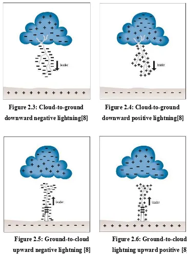
Basically, there are four types of lightning, which are cloud-to-ground downward positive, cloud-to-ground downward negative, ground-to-cloud upward positive and ground-to-cloud upward negative as shown in Figure 2.3 to 2.6 respectively [8].
[image:24.595.121.486.150.645.2]
Figure 2.3: Cloud-to-ground Figure 2.4: Cloud-to-ground downward negative lightning[8] downward positive lightning[8]
Figure 2.5: Ground-to-cloud Figure 2.6: Ground-to-cloud upward negative lightning [8] lightning upward positive [8]
![Figure 2.1 Types of overvoltage [3]](https://thumb-ap.123doks.com/thumbv2/123dok/563310.66518/22.595.137.478.506.719/figure-types-of-overvoltage.webp)
![Figure 2.2: Number of days with thunderstorm,Td in Malaysia[7]](https://thumb-ap.123doks.com/thumbv2/123dok/563310.66518/23.595.95.544.409.618/figure-number-days-thunderstorm-td-malaysia.webp)