COLOUR DETECTION AND COUNTING SYSTEM FOR TOY BALLS
WONG WAI KIT
This report is submitted in partial fulfilment of the requirements for the award of Bachelor of Electronic Engineering (Industrial Electronics) With Honours
Faculty of Electronic and Computer Engineering Universiti Teknikal Malaysia Melaka
UNIVERSTI TEKNIKAL MALAYSIA MELAKA
FAKULTI KEJURUTERAAN ELEKTRONIK DAN KEJURUTERAAN KOMPUTER
BORANG PENGESAHAN STATUS LAPORAN
PROJEK SARJANA MUDA II
Tajuk Projek : COLOR DETECTION AND COUNTING SYSTEM FOR
TOY BALLS
Sesi Pengajian : 2010/2011
Saya WONG WAI KIT
mengaku membenarkan Laporan Projek Sarjana Muda ini disimpan di Perpustakaan dengan syarat-syarat kegunaan seperti berikut:
1. Laporan adalah hakmilik Universiti Teknikal Malaysia Melaka.
2. Perpustakaan dibenarkan membuat salinan untuk tujuan pengajian sahaja.
3. Perpustakaan dibenarkan membuat salinan laporan ini sebagai bahan pertukaran antara institusi pengajian tinggi.
4. Sila tandakan ( √ ) :
SULIT*
*(Mengandungi maklumat yang berdarjah keselamatan atau kepentingan Malaysia seperti yang termaktub di dalam AKTA RAHSIA RASMI 1972)
TERHAD** **(Mengandungi maklumat terhad yang telah ditentukan oleh organisasi/badan di mana penyelidikan dijalankan)
TIDAK TERHAD
Disahkan oleh:
__________________________ ___________________________________
(TANDATANGAN PENULIS) (COP DAN TANDATANGAN PENYELIA)
Tarikh: 02 MAY 2011 Tarikh: 02 MAY 2011
iii
“I hereby declare that this report is the result of my own work except for quotes as cited in the references.”
Signature : ………
Author : WONG WAI KIT
iv
“I hereby declare that I have read this report and in my opinion this report is sufficient in terms of the scope and quality for the award of Bachelor of Electronic Engineering
(Industrial Electronics) With Honours.”
Signature : ………...
Supervisor‟s Name : NOOR ASYIKIN BT SULAIMAN
v
For my lovely mum and dad, thanks for your sacrifice towards my success. For my Final Year Project supervisor, Mdm. Noor Asyikin Bt Sulaiman, thanks for
all your supports.
vi
ACKNOWLEDGEMENTS
First of all, I would like to thank my Final Year Project supervisor Mdm Noor Asyikin Bt Sulaiman for her support and guidance through this entire project.
I would like to express my appreciation to my beloved parents who always support and never encourage me to finish my Final Year Project and study without any delay. Besides, they always support and understand me while giving me idea to accomplish my project.
vii
ABSTRACT
viii
ABSTRAK
xi
4.2.4 Result Of Output Signal Of AND A Gate 35 (7408) From LDR1 Sensor Of
Colour Detection Circuit Is „LOW‟ Or Logic „0‟ 4.2.5 Result Of Output Signal Of AND A Gate 36
(7408) From LDR1 Sensor Of
Colour Detection Circuit Is „HIGH‟ Or Logic „1‟ 4.2.6 Results For Output Signal Of AND A Gate 38
(7408) From Colour Detection Circuit By Using Digital Oscilloscope
4.3 The Results Of Counter Circuits 40
4.3.1 Results For Output Signal Of Counter Circuit 42 By Using Digital Oscilloscope
4.4 The Results Of DC Motor Response From PIC 44 Microcontroller Circuit
4.5 Discussions 46
V CONCLUSION AND RECOMMENDATION 49
5.1 Introduction 49
5.2 Conclusion 49
5.3 Recommendation 50
xii
across series connection of 4.7kΩ resistor with LDR1 sensor
4.2 Maximum output voltage (Vmax) of BLUE colour toy balls 32
across series connection of 4.7kΩ resistor with LDR1 sensor
4.3 Maximum output voltage (Vmax) of RED colour toy balls 32
across series connection of 4.7kΩ resistor with LDR1 sensor
4.4 Maximum output voltage (Vmax) of BLUE colour toy balls 33
across series connection of 4.7kΩ resistor with LDR2 sensor
4.5 Maximum output voltage (Vmax) of RED colour toy balls 33
across series connection of 4.7kΩ resistor with LDR2 sensor
4.6 Maximum output voltage (Vmax) of RED colour toy balls 34
xiv
4.2 Output signal of AND A Gate (7408) for LDR1 sensors 36 from the Detector Circuit is „HIGH‟ or Logic „1‟
4.3 Output Signal of AND A Gate (7408) from Detector Circuit 38
4.4 Analysis results from Figure 4.3 39
4.5 Simulation results of initial steps of output signals 40 from counter circuit
4.6 Simulation results of final steps of output signals from 41 counter circuit
4.7 Waveform of output signals from BCD Decade Counter (4510) 42
4.8 Analysis results from Figure 4.7 43
4.9 Waveform of output signals for DC motor 44
xv
LIST OF ABBREVIATIONS
LDR – Light Dependent Resistor IC – Integrated Circuit
DC – Direct Current AC – Alternative Current LED – Light Emitting Diode
PIC – Programmable Interface Circuit BCD – Binary Coded Decimal
OP-AMP – Operational Amplifier A/D – Analog to Digital
1
CHAPTER I
INTRODUCTION
1.1 Project Background
Most of people today consider electronic gadget as an important device that can help improving and helping their daily life. People reliance upon electronic devices has risen significantly throughout the past ten years, and they demand for cheaper, convenient and faster ways to complete their task such as detecting, sorting, and counting coloured objects. Therefore, lots of products are designed to meet the demand.
Basically, there are many types of colour sensor for detecting the colour objects such as Infrared, IR sensors, digital cameras and etc. Unfortunately, some of the prices of colour sensors in market are expensive. Therefore, this project attempts to design cheaper colour detection and counting system using LDR.
1.2 Objectives
The main objectives of the project are:
i. To identify and distinguish the colour of toy balls.
2
iv. To segregate the toy ball according to its colour.
1.3 Problem Statements
Some of color sensing devices are using infrared (IR) concept where it requires a pair of emitter and receiver. Unfortunately, if either one of the components from IR sensor was malfunction, then it is not easy to detect because the ray is invisible. Meanwhile, it is quite challenging to fix the angle between the transmitter and receiver.
In contrast, this project uses LED to emit light to the object then LDR will receive the reflected light from the target. The reason is because the light emitted from LED is visible if compare to IR sensor. So, LED and LDR are easy to use and manageable especially in fixing the angle between them. Since, different colours reflect in different intensity light, and then LDR is capable to be a colour sensor.
1.4 Scope of Work
The scopes of this project are:
i. LDR is used as a sensor in colour detection circuit.
ii. Decimal counter is used to count the number of collected toy ball in container. iii. Seven segment displays is used as display.
iv. DC motor is used to push the toy ball into container.
v. Only RED, GREEN and BLUE colour of toy balls are used in this project.
1.5 The advantages of the project
3
The following advantage from this project is capable to count automatically the amount of target in the container. The decade counter is able to count and display the amount of colour toy balls in the container.
1.6 Overview of the Report
This report is divided into five chapters. Below is brief explanation of each chapter.
Chapter 1 briefly discusses about the introduction of the project. This chapter covers objectives, problems statements, scopes of work, and the advantages of this project.
Chapter 2 covers literature review and theoretical aspect of this project. This chapter is an import part of the project in which it discusses the concept used and also about the colour sensing units and counter as the main element of the project. All the aspects needed to be consider such as specification, requirements and standards of the colour sensing units and counter are covered in this chapter.
Chapter 3 covers the methodology used in this research and development. The LDR used as the colour sensor units is discussed as well as the construction of the circuit. For simulation, the circuit is tested using engineering software.
Chapter 4 will discuss and analyze the simulation results including the output of LDR sensors, DC motors and counters response for this project.
4
CHAPTER II
LITERATURE REVIEW
2. 1 Counter
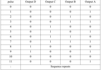
A counter is a device that performs counting operation. Counters may be used to count operation, quantities, or periods of time. They may also use for dividing frequencies, addressing information in storage, or temporary storage. The modulus for a counter is represented as the number of states. For example, the term of „MOD-10‟ number is the number of states that counting from 0 to 9 and once completed it return to 0 again.
In practice, there are two types of counters for performing count operation which is count up or count down. When users have set the counter as count up mode, then counter will count in increment of value. If, users have set the counter as count down mode, then counter will count in decrement of value.
5
„1‟ when clock triggered, the output will be 0011. On the contrary, if the counter is D mode then the following clock pulse will make it 0001. [1]
It also has RESET pin, so that user can reset the counter whenever necessary. When the pin is active mode such as logic „1‟ on the RESET input can clear the counter to 0000 for the counter output can reset to 0000 (in case of 4-bits counter) when desired. For example, the logic „1‟ on the RESET input can clear the counter to 0000.[1]
The output for BCD decade counter is equal to 4-bits of binary output. Normally, this output will feed with another IC such as decoder IC for observing the numerical digits in 7-segments display.
6
Table 2.1 Results at output of Decade Counter CD 4510 when pulses is triggered
pulse Output D Output C Output B Output A
Normally, numerical digits can be shown in arrangement group of LEDs or 7 Segment Display. However, to display the numerical digits in the arrangement group of LEDs is considered difficult if compared with 7 Segment Display.
7
Figure 2.2 Arrangement of 7 Segment Display
In order to display the corresponding character on the 7 Segment Display, a BCD to 7 Segment Decoder is necessary to be connected and fulfil the operation. Generally, there are various types of BCD to 7 Segment Decoder such as 7447N and 4511. Although both decoder are workable with 7 Segment Display but the method for switching the outputs from the decoder to 7 Segment Display between them are different. Table 2.2 is shown comparison between these two decoders.
Table 2.2 Comparison method for processing the outputs from the decoder BCD to 7 Segment Decoder (7447N) BCD to 7 Segment Decoder (4511)
The outputs are active LOW. The outputs are active HIGH. Required to connect with NOT gate/
inverter IC at the outputs.
Not required to connect with NOT gate/ inverter IC at the outputs.
2.3 Variable Resistor
Variable resistor is an electronic device that consists of track with connections at both ends and the wiper which can be switchable along the track as the user turn the spindle. The material for the track of potentiometer may make from carbon, cermets (ceramic and metal mixture) or coil of wire (for low resistance). The architecture design of the track may design in rotary or straight track version. The name of the potentiometer is called slider when the track is designed in straight version. [3]
8
two electrical connections are required to be connected at the wiper and another one end of the track. However, if user wants the variable resistor used as potentiometer, three connections will be used for electrical connections respectively. [3]
Meanwhile, some reference book or article may name that variable resistor as potentiometer. Normally, the manufacturer will specify the maximum resistance, linear or logarithmic track, and physical size for the potentiometer. The information related to the resistance and type of track is normally marked on the body of potentiometer. For example, when the words are marked 10K LIN these represented 10kΩ in linear track. However, if the words are marked 1M LOG these represented 1MΩ in logarithmic track.
Besides, potentiometers are commonly used to control electrical devices such as volume controls on audio equipment. However, potentiometers are rarely used to directly control significant power (more than a watt), since the power dissipated in the potentiometer would be comparable to the power in the controlled load. The Figure 2.3 below is shown the real image of a variable resistor.
9
2.4 DC Motor
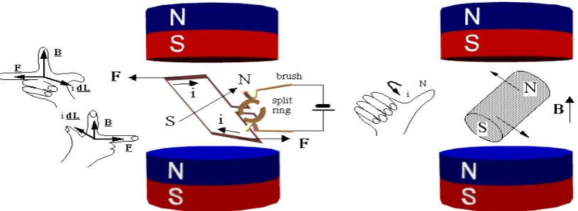
Motor is a device which converts electrical energy into mechanical energy. For a DC motor, its input electrical energy is supplied with a DC supply. In practical, the field winding of a DC motor will produce a required magnetic field while armature conductors acted as current carrying conductor and then the armature conductor will experience a force. So, when a conductor is carrying a current and place perpendicular in a magnetic field, the overall armature will experience a torque and start rotating which is show in Figure 2.4 below. [4]
Figure 2.4 Torque exerted on armature and armature start rotating
Any current carrying conductor produces its own magnetic field around it, hence this conductor also produce its own flux, around. The direction for determine the flux can be determined with Right hand thumb rule. However, the flux produce by the permanent magnet is considered main flux. In order to determine the direction of rotation of a DC motor, the Figure 2.5 is shown the method for determine the rotation of armature by using Fleming Left Hand rule. [4]