PROJECT COMPLETION REPORT
FOR
(SHORT TERM) RESEARCH GRANT
DEVELOPMENT OF A STEP-NC CONTROLLER
SYSTEM FRAMEWORK AND IMPLEMENTATION IN
UTeM
Principal Researcher : Engr. Dr. Mohamad bin Minhat
Co-Researchers : 1. Nik Mohd Farid bin Che Zainal Abidin (FKP) 2. Mohd Shukor bin Salleh (FKP)
Project Code No. : PJP/2010/FKP (10A) S668 Report Submission Date : 12 April 2013
Department of Process
Abstract
Abstract
To meet the challenges of the ever-increasingly globalized manufacturing economy, open, agile, distributed, interoperable and intelligent Computer Numerical Controlled (CNC) machine tools are one of the key enablers. Efforts to improve or even replace the current CNC data model, that is, G-codes, have been made by many researchers. This is because G-codes have become a bottleneck to achieving the afore-mentioned CNC machine tool. In recent years, the STEP-NC data model has been considered a promising alternative to G-code. A STEP-NC controller with Function Block (FB, otherwise known as IEC 61499) architecture has been developed in this research. This STEP-NC controller represents the prototype of a possible future CNC system. It works with STEP-NC data and can automatically generate a part program to be executed on a machine tool. The STEP-NC controller consists of four main modules: (1) Data Input Module, (2) STEP/FB Translator, (3) Tool-Path Generator and (4) Adaptor-FB-Controller board. The system has a layered structure, making it easy to manage and extend. It unifies the functionalities of simulation and real machining under the same interface. Thanks to the use of function block technology in the form of the embedded controller software, the machining simulation is also near real-time. The architecture has been tested through a system application, using a CNC milling machine. It has been proved that use of function block technology allows the development of an open and distributable CNC system. In addition, the controller can also support remote management and configuration, a feature that could be useful in an environment featuring multiple machine tools (for example, flexible manufacturing systems).
The research work reported in this thesis has been published in one journal paper [Salleh M.S., et al., 2011 In Press] and presented at two international conferences [Zainal Abidin N.F., et al., 2011, Salleh M.S., 2011].
Keywords: CNC; STEP; STEP-NC Controller; Function Block
UTeM/CRIM/RND/010
CENTRE FOR RESEARCH AND INNOVATION MANAGEMENT
PROJECT COMPLETION REPORT A. PROJECT DETAILS
Principal Researcher : ____Engr. Dr. Mohamad bin Minhat___________________________________________
Faculty/Centre : ____Faculty of Manufacturing Engineering (FKP) / Department of Process________________
Project Title : Development of a STEP-NC Controller System Framework and Implementation in UTeM
Project No. :_____PJP/2010/FKP(10A) S668_____________________________________________
Project Focus Area : a) Green Technology b) Emerging Technology
c) System Engineering d) Human Technology Interaction
Contact No. (Off./Hp) : __0196716879 _________________ E-mail : [email protected]______________
Project Duration (date) : Starts __1 March 2010 _________ Ends: ___31 August 2011____________________
B. PROJECT ACHIVEMENT AND PERFORMANCE
I. OBJECTIVES (IN ORDER OF PRIORITY)
Provide details as stated in the original proposal. Describe the extent to which the objectives of the research have been achieved and relate the significance of the research to recent work in the field.
The research project has successfully achieved the following
objectives:-1. Successfully build the system framework and implementing the STEP-NC controller in UTeM. 2. A new research group and final year projects have been set up.
UTeM/CRIM/RND/010
II. ATTENDED CONFERENCE/SEMINAR/SYMPOSIUM
Provide name of the event, date, venue and organizer related to the research project. Please compare against targets
1. N.F. Zainal Abidin, M.S. Salleh, M. Minhat and H. Arep. “STEP-NC Controller ̶ Testing and Commissioning for Open Architecture Control System”, MUiCET 2011 Nov 13-15, Batu Pahat, Malaysia.
2. Mohd Shukor Salleh, Mohamad Minhat, Nik Mohd Farid Che Zainal Abidin and Hambali Arep “System Framework Tools for Future CNC Machining”, 2nd International Conference on Mechanical and Manufacturing Engineering 2011, PICC Putrajaya Kuala Lumpur
Malaysia. 3.
4.
III. PUBLICATION
List title of papers, books, etc arising from the research (indicate if they were indexed or non-indexed).
eg. A.Shaaban, A.Fujita, A.J.Williams and I.R.Harris, ‘Studies of Zr-additions on Near-Stoichiometric Nd-Fe-B Cast Ingots’: Proceedings of the 17th International Workshop on R.E.Magnets and Their Applications, 18-22 August 2002, Newark, USA. pp
618-622
Indexed Journal : total number = Accumulative Impact Factor =
1. Mohd Shukor Salleh, Mohamad Minhat, Nik Mohd Farid Che Zainal Abidin and Hambali Arep, “System Framework Tools for Future CNC Machining”, International Journal of Integrated Engineering (IJIE), Accepted.
2. 3.
Non-Indexed Journal : total number =
1. 2. 3.
IV. HUMAN CAPITAL DEVELOPMENT
Name and number of students trained under this project.
Type of Student: PhD/Masters/PSM/SRA/undergraduate. If undergraduate, indicate whether they intend to continue research/study PhD
Mohd Elias bin Daud, GD100008, "Interoperable CNC Machine Via LabVIEW and STEP-NC Data Model For Milling Operation Framework", UTHM, Batu Pahat Malaysia.
PSMI and PSMII UTeM
Nurulhuda Alladdin, B051010063, “STEP-NC: New Perspective in CAx System in Malaysia Context.” Syazwani Yaacob, B051010234, “Mach 3 CNC Machine Software Familiarization and Machining”
Thevabalan a/l Sellappan, B050910305, “ISO14649 Example 2 STEP-NC Manufacturing on CNC 3 Axis Sherline Milling Machine” Mariani Bt. Hassim, B050810224, “Feature-based CNC Machining using IEC 61499 Function Block Technology”
Mohd Ikhwan Bin Muhamad, B050610197, “Intelligent and Interoperable Manufacturing System”
UTeM/CRIM/RND/010
V. ATTENDED TRAINING/COURSES
Provide training/courses/workshop being attended under this grant.
Nil
VI. INTELLECTUAL PROPERTY AND COMMERCIALISATION
Describe any patentable/commercially exploitable results/potential industrial partner/collaborative work. The controller is capable of a potential patented registration.
VII. RESEARCH PERFORMANCE
1. Was there any significant change in the research compared with the original proposal? If YES, give reasons for changes.
Request for variation of VOT 21000 to VOT 35000 for RM 1,625.00.
2. Did the research proceed as expected and on time?
No. It was extended for six months and the new expiry date was 31 August 2011.
3. Were there any circumstances which aided or impeded the progress of the research?
If YES, give details of problems and explain the steps you took to overcome them. Examples could include difficulties in staff recruitment, late delivery of equipment, equipment malfunction etc.
Yes. Huge teaching and learning academic load of researchers impeded the progress of the research.
VIII. FURTHER RESEARCH WORK
(1) Has the research led to further grant applications?
If YES, give details of the outcome: grant applications, dates and grant reference number. Indicate value of any grants applied/awarded.
Nil
(2) Has the research stimulated further work in other ways? If YES, provide details on research parties and agencies.
Yes. PhD
Mohd Elias bin Daud, GD100008, "Interoperable CNC Machine Via LabVIEW and STEP-NC Data Model For Milling Operation Framework", UTHM.
UTeM/CRIM/RND/010
IX. FINAL STATEMENT OF ACCOUNTS
Items 29000A 21000 24000 27000 28000 29000B 35000 36000 TOTAL
(RM) 1. Total approved
budget - 2375 - 2000 - - 11625 - 16000
2. Total actual expenditure and amount
committed
2375 781.9 11625 14781.9
3. Total Balance 0 1218.1 0 1218.1
UTeM/CRIM/RND/010
SUMMARY OF RESEARCH PERFORMANCE
The following section is to be completed by the Principal Researcher. Please tick (√) the appropriate boxes.
(1) Objective(s) of project N t Achieved Not Fully Achie ed √ Fully Achieved (2) Level of achievements
The number and quality of achievements are as follows:-
Quality
(iii) Commercialised Products ______
(iv) Manpower Trained
- M Eng ______
- PhD __1__ √
- Others (PSMI and PSMII) __ 5___ √ (v) Other Contributions/Achievements
(Pls specify: ______________________________) ______
(3) Potential application of results √
(4) Overall Project Completion √ Behind Schedule On Schedule Ahead of Schedule 5) The possibility of utilisation of equipment purchased by staff and Poor
UTeM/CRIM/RND/010
C. IMPORTANT NOTES
1. Three (3) copies of hard bound final project report must be submitted to CRIM within 2 months
after the project completed. The report must follow a standard format.
2. The account will be closed within 2 months after the project completed. Principal Researcher
should therefore submit all claims/invoices for any outstanding purchase orders or commitments as soon as possible but no later than the aforementioned deadline.
3. Failure to submit the hard bound final project report will result less priority in consideration for subsequent research grant applications.
D. DECLARATION OF PRINCIPAL RESEARCHER
I acknowledged UTeM in providing the fund for this research work. I certify that the information given in this final project report is true to the best of my knowledge.
Signature : Official stamp : Name : Designation : Date :
E. ENDORSEMENT AND ACCEPTANCE
ENDORSEMENT BY DEAN or DEPUTY DEAN (RESEARCH), FACULTY / CENTRE (Please state / comment on the performance of the project)
____________________________________________________________________________________________
________________________________________ __________________ Signature & Official Stamp Date
F. ACCEPTANCE BY CRIM
Received 1 copies of hard bound and 1 copy of softcopy (CD) : _______________________ (name)
_______________________________________ __________________
CRIM Official Stamp Date of received
Notes : 1) ______________________________________________________________________
2) ______________________________________________________________________
Table of Contents
Table of Contents
ABSTRACT ...
TABLE OF CONTENTS ...
CHAPTER 1 - INTRODUCTION ... 1
1.1 CAX CHAIN ... 2
1.2 NUMERICAL CONTROL AND COMPUTER NUMERICAL CONTROL ... 4
1.3 CNC SYSTEMS AND CONTROLLERS ... 4
1.4 THE DATED G-CODE ... 5
1.5 EMERGING DATA MODELS AND TECHNOLOGIES ... 7
CHAPTER 2 - CNC SYSTEMS, STEP-COMPLIANT CNC AND FUNCTION BLOCKS ... 9
2.1CNCSYSTEMS ... 9
2.2 SOME ADVANCEMENTS OF CNC SYSTEMS ... 12
2.3 STEP-NC RELATED RESEARCH ... 14
2.3.1 Research Work in Germany ... 15
2.3.2 Research Work in the UK... 16
2.3.3 Research Work in the USA ... 16
2.3.4 Research Work in Korea ... 17
2.3.5 Research Work in Other Countries ... 18
2.4 RESEARCH WORK IN NEW ZEALAND ... 19
2.5 FUNCTION BLOCKS AND STEP-COMPLIANT CNC SYSTEM ... 20
2.6 SUMMARY ... 22
CHAPTER 3 – IMPLEMENTATION ... 23
3.1IMPLEMENTATION ... 24
3.1.1 Software Environment ... 24
3.2 PROCESSING STEP-NC DATA ... 28
3.2.1 STEP/FB Translator Graphic User Interface ... 28
3.3FUNCTION BLOCKS EDITOR ... 29
3.3.1 Raw Material Data ... 31
3.3.2 Set-up Data ... 32
3.3.3 Machine Tool Database ... 34
3.3.4 Cutting Tool Database ... 38
3.4 TOOL-PATH LIST ... 40
3.5 SIMULATION ... 43
3.6 ADAPTOR-FB-CONTROLLER ... 45
3.7 MACHINE EXECUTION ... 46
3.8 EXAMPLES OF MACHINED PARTS ... 49
3.9 SUMMARY ... 50
CHAPTER 4 - CONCLUSIONS AND FUTURE WORK ... 51
4.1RECAP OF THIS RESEARCH ... 52
4.2 NOVEL CONTRIBUTIONS TO THE FIELD ... 53
4.3 RECOMMENDED FUTURE WORK ... 55
REFERENCES ... 57
APPENDIX A SUPPORTING DOCUMENTS ... i
Introduction
Chapter 1 - Introduction
Machining or metal cutting became an essential business around the time of the industrial revolution. In 1775, John Wilkinson invented a lathe machine (cannon-boring) in England and it was the only one of its kind to produce the smooth, tight tolerance bores required. Later, in 1818, Eli Whitney invented a milling machine in New Haven, Connecticut. The spindle of Eli Whitney's milling machine was moved from being horizontal to vertical. This is commonly seen in the Bridgeport style knee-mill. The year 1952 brought Mr. John Parson’s Numerical Controller (NC) milling machine. Parsons worked to attach servomotors to the X and Y axes, controlling them with a computer that read punch cards to give them positioning instructions.
G-code is a common name for the programming language for an NC machine tool. RS-274D is the recommended standard for NC machines developed by the Electronic Industry Association in the early 1960s. The RS-274D revision was approved in February 1980, and later became an international standard [ISO 6983, 1982]. This standard provided a basis for the writing of code programs. Over the years, the G-code languages have been widely used for almost all Computer Numerical Controlled (CNC) machines. It is hoped that modern CNC machine tools will evolve from pure controllers into integrated systems with both decision-making and control abilities so that in a Computer-Aided Manufacturing (CAM)/NC system the operator can view and modify any aspect of a workpiece or operation, including tooling, machine parameters, part geometry, and tolerances at the machine controller.
Although Computer-Aided Design (CAD) systems became available as early as the 1960s, their progress was severely hampered by the capability of the computers at the time [Xu, 2009]. At the CAD level, there is the issue of the proprietary nature of software, where some of the occurrence of data is lost during the transfer process [Du et al., 2005]. At the Computer-Aided Process Planning (CAPP) level, today’s systems perform NC programming with insufficient consideration of real machining
Introduction
capabilities and workpiece characteristics [Fortin et al., 2004]. The first CAPP system was developed in 1976 under the sponsorship of Computer-Aided Manufacturing International (CAM-I) [Xu, 2009]. The issue continues today at the CNC level, that is, CNC machines receive no information about actual workpiece characteristics and functional manufacturing processes [Wang et al., 2005].
In this chapter, an introduction of CAD, CAM and CNC (CAx) chain and design-to-manufacturing integration using STandard for the Exchange of Product data (STEP), STEP-compliant Numerical Control (STEP-NC) and IEC 61499 (Function Blocks) is given. A brief review on STEP [ISO 10303-1, 1994], STEP-NC [ISO 14649-1, 2003] and Function Blocks [IEC 61499-1, 2005] is also given.
1.1
CAx Chain
For the last 50 years, manufacturing industries have been looking for more efficient processes for manufacturing products with CNC machines [Nassehi et al., 2006b]. The manufacturing process divides information, databases and data models into two parts, that is, product and process data.
Process data are the information and technology needed to remove materials, using machining and machine tools data. The product data describe the product in a format of workpiece geometrical databases, manufacturing files and programming [Venkatesh et al., 2005]. It was followed by digital drawings engaging CAD and CAPP which were carried out manually by engineers utilizing CAD files. In time, development saw CAM more closely connected to CNC systems.
The technologies are diverse. They concern systems as well as functionality. Computer-aided part programming is elaborated as an information-intensive activity and an excellent tool in the development of future CAPP systems [Allen et al., 2005]. Further, state-of-the-art CNC systems should incorporate product and process data in order to offer a bi-directional interface over the CAx chain with a high-level description which may consist of geometrical and manufacturing information.
Product data information has to be transferred between various manufacturing
Introduction
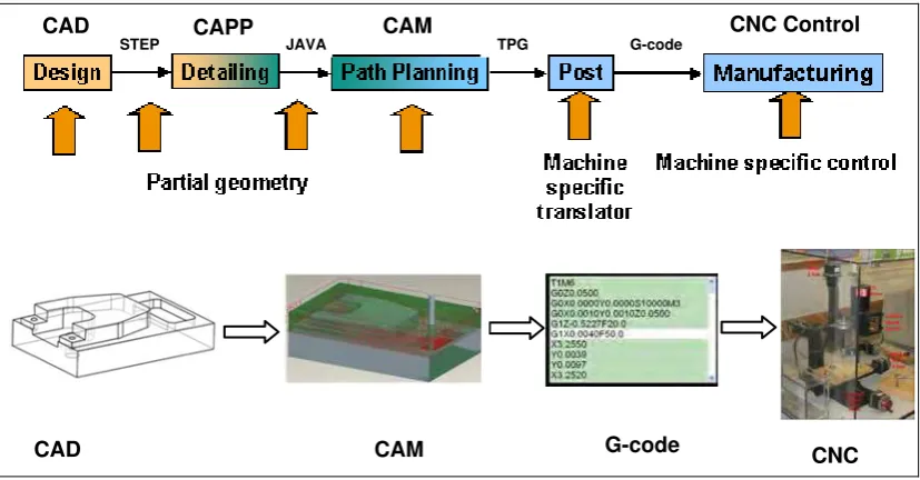
facilities to complete the task [Cang et al., 2006]. Manufacturing industries have attempted to share and to transfer product model data in the efficient way. A typical CAx chain is shown in Figure 1.1. Nowadays G-code programs are generated by CAM tools, using geometric data from CAD systems as input [Minhat et al., 2009a]. However, the CNCs of different vendors implement different versions of G-codes, which lack any portability and lead to proprietary CAx chains [Wang et al., 2007a, Xu et al., 2006a].
This information is handled by a special unit within a CAM tool called a post-processor which operates through: (1) the G-code, (2) machine tools and (3) libraries of cutting tools. The post-processor generates an exact procedure of machining processes, which is described in a G-code file.
Systems
Figure 1.1 A typical CAx chain [Minhat et al., 2009a]
G-code is essentially based on the tool-path and machine status description implemented by industry as a way to move three-dimensional (3D) geometry between CAD and CAM systems and CNC machine tools, by exchanging manufacturing process information and product data between the systems [Hardwick & Loffredo, 2006]. In the development of NC to CNC, most CNC machines were programmed using the G-code language, which was designed to sequentially document and pass instructions to the controls of single machine tools [Lee et al., 2006].
Introduction
1.2
Numerical Control and Computer Numerical Control
Numerical control describes the control of machine movement and various other functions by instructions expressed as a series of numbers and initiated via an electronic control system [Weck, 1984]. An NC machine usually encompasses (1) a control system comprised of microprocessor-based hardware and software and (2) a servo system that includes transducers to measure speed, motion, and other data related to the machine’s environment, actuation devices that accomplish accurate positioning and motion, and mechanical and electronic peripheral components that are required for specific applications.
CNC is the term used when the control system utilizes an internal Personal Computer (PC) [Smid, 2003] and it links elements between the operator interface and machine tool interface. CNC technology has the following advantages over NC technology: programs can be entered at the machine and stored in memory, and are easier to edit, so programming of parts and design time are reduced. Computers can be connected to other computers worldwide, either by direct modem connection or through a network, thereby allowing part programs to be transmitted directly to remote CNC machines [Wang, 2008a].
It is expected that CNC will have thinking capability and a controlling strategy before, during, and after the execution of the manufacturing task, so that it can be effectively executed while dealing with unexpected changes occurring on the shop floor [Chen et al., 2003]. There is also a requirement to encompass the entire scope of CNC machining in e-manufacturing [Choi et al., 2006]. It is also expected that CNC will use an interoperable language for design and manufacturing. This is essentially a new data model, which should provide a CNC with all the information about “what-to-make” (geometry or tasks).
1.3
CNC Systems and Controllers
The primary functions of NC and CNC are focused on machine control. Although the application requires special control activities, all machine tools are programmed to accomplish three major objectives:
Introduction
• Positioning—The position of a tool is controlled in two or three axes
• Motion—The direction and speed of a tool is controlled so that the motion of the tool is predictable
• Function — Other machine functions (for example, controlling the tool index change or moderating the feed-rate) are controlled so that the cutting tool can better adapt to its environment.
The majority of the controls use a two or three axes Cartesian coordinate system (X, Y, and Z) to accomplish positioning. Some machines have tools that can be rotated through one, two, or three axes of rotation or degrees of freedom. Both workpiece and tool may be moved or rotated. Machine workspace is a bounded plane or volume in which the tool and workpiece can be positioned, through which controlled motion can be evoked.
The development of advanced CNC controllers is driven by both CNC manufacturers and end users. Park et al. organized and managed various control software modules dynamically by using process and resource models [Park et al., 2006]. Open CNC controllers have been extensively researched. In modern control theories, the adaptive control functions of these machine tools have been significantly improved [Wang et al., 2008, Keshavarzmanesh et al., 2008]. Interoperability can be defined as the ability of two or more CNC controllers to exchange information with no barriers. This is best described as having plug-and-play features [Wang et al., 2006a]. A key enabler for such a plug-and-play feature is reconfigurability and modularity to go hand-in-hand to give CNC controllers additional features such extensibility and scalability [Bi & Wang, 2009].
1.4
The Dated G-code
Machine tools have evolved from simple machines with controllers that had no memory, driven by punched tape, to today’s highly sophisticated CNC multi-process workstations, over the last 5 decades [Xu & Mao, 2004]. These workstations have capabilities such as multi-axis control, adaptive control, error compensation and multi-process manufacture (for example, combined mill/turn/laser and grinding
Introduction
machines). G-code is commonly known as a low-level language that is based on the tool-path and on machine status descriptions. It delivers the geometrical character and machining strategy to CNC machines. According to ISO 6983, G-code is based on the following stipulations:
• Preparatory functions — From G00 to G99
• Miscellaneous commands — M (also called Machine functions)
• Axis motion commands — X, Y, Z, A, B, C
• Feed and speed commands — F (Feed-rate), S (Spindle Speed)
• Identification commands — N (Block number)
• Cutting Tool — T.
These days, G-code is generated automatically by post-processors in most CAD/CAM software systems such as Pro/E, MasterCam and UX (Figure 1.2). As a language standard, G-code has made great contributions to enhancing modern manufacturing technology. Although almost all CNC machine tools use some kind of G-code to control their operations, a number of problems still exist and in many ways hamper further advancement of CNC technology.
CAD CAPP CAM CNC Control
STEP JAVA TPG G-code
CAD CAM G-code CNC
Figure 1.2 Post-processor and G-code in the art-to-part CAx chain
G-code only focuses on the path of the Cutter Locations (CLs) with respect to the machine axes, rather than the machining tasks with respect to the part. They have to
Introduction
be processed by a machine-specific post-processor, only to obtain a set of low-level, incomplete data that makes verification and simulation difficult, if not impossible. Therefore, it is clear that much of the CAD data is not available on the machine. G-code is a kind of number-based language. The standard defines the syntax of program statements, but in most cases leaves the semantics ambiguous. So it is very hard for a non-technical person to understand. The characteristics of components are hidden behind a huge number of letters and digits.
G-code only supports one-way data flow from design to manufacturing. The changes on the shop-floor cannot be directly fed back to the designer. Hence, invaluable experience on the shop-floor is lost. It only defines three modes of motion, G01, G02, and G03. G01 describes linear motions whereas G02 and G03 describe circular motions. G-code does not support spline data, which makes it incapable of controlling five or more axes milling.
1.5
Emerging Data Models and Technologies
The ISO committee has been working since the mid 1980s toward unified and integrated standards to describe all the aspects of a product during its lifecycle. This endeavour led to the establishment of the international standard ISO 10303 STandard for the Exchange of Product data (STEP), which has its foundations in many of the earlier aforementioned standards [Liu et al., 2006a].
STEP is a family of standards defining a robust and time-tested methodology for describing product data throughout the lifecycle of a product. It is now widely used in CAD and PDM systems. Major aerospace and automotive companies have proven the value of STEP through production implementations, resulting in saving of $150M per year in the US [Gallaher et al., 2002].
Recently, STEP has been extended to cater for manufacturing data modeling and execution with an aim to filling the information gap between CAx chain and CNCs [Brecher et al., 2006]. The standard is informally known as STEP-compliant Numerical Control, otherwise known as STEP-NC.
Introduction
In this research a novel open architecture of a STEP-NC controller is proposed, which aims to meet these challenges and provide some insight into a future generation of CNCs with open, flexible architecture [Minhat et al., 2008]. This STEP-NC controller is capable of accepting STEP-NC data directly. The software architecture of this STEP-NC controller is based on the open reference architecture known as the IEC 61499 Function Blocks standard. The IEC 61499 function blocks will enable easier program distribution, integrated visualization and improved real-time control characteristics.
CNC Systems, STEP-Compliant CNC and Function Blocks
Chapter 2 - CNC Systems, STEP-Compliant
CNC and Function Blocks
CNC systems sit at the end of the process starting from product design using CAD tools to the generation of machining instructions that instruct a CNC machine to produce the final product. This process chain also includes CAPP and CAM [Minhat et al., 2008]. STEP/STEP-NC standards, in conjunction with CNC systems, have made it possible to produce goods with consistent quality, and enabled the industry to enhance productivity with a high degree of flexibility in a manufacturing system. STEP/STEP-NC standards alternatively offer an open architecture for industrial automation and integration systems. Despite the short history of CNC systems and STEP/STEP-NC, considerable research has already been carried out both internationally and within countries/organizations [Wang, 2009].
This chapter provides a review of four areas of research: (1) CNC systems, (2) recent advancements of CNC, (3) STEP-compliant CNC systems with function blocks and (4) other STEP-NC related research. The first two types of CNC systems use G-codes whereas the third and fourth are STEP-compliant.
2.1
CNC Systems
The Electronics Industries Association 1965 defines the NC system as ‘a system in which actions are controlled by the direct insertion of numerical data at some point’ [Childs, 1969]. CNC is the term used when the control system utilizes an internal personal computer (Figure 2.1).
CNC Systems, STEP-Compliant CNC and Function Blocks
Personal Computer Machine Control Unit CNC Machine
Figure 2.1 CNC utilizes an internal personal computer
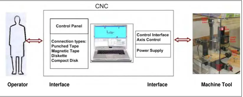
Since the first industrial revolution about two centuries ago, the NC system has had a significant impact on the manufacturing industry. The system can be seen as a “coupling” between the operator and the machine tool (Figure 2.2). It is believed that NC history began in 1947 when John Parsons began experimenting with the idea of generating thru-axis curve data and using that data to control machine tool motions [Minhat et al., 2009b].
Operator Interface Interface Machine Tool
Figure 2.2 Operator and machine tool
As previously mentioned, most of the CNC controllers in conventional CNC systems run with G-codes, the programming language standardized by the ISO 6983. G-code programs are usually generated by CAM tools and work by setting up a machining process through defining feature information, cut volume, machining procedures, tool
CNC Systems, STEP-Compliant CNC and Function Blocks
information and machining conditions, used as input in spite of the geometrical data from CAD tools.
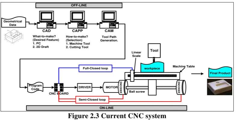
The most basic function of any conventional CNC is automatic, precise and consistent motion control so that improved automation results. CNC machines have to maintain consistency, accurate machine parts and repeatable specifications. This may mean that once a part program command is validated, tens of thousands of identical parts can be easily produced with the required precision and consistency. Figure 2.3 shows a current CNC system.
CAD
Figure 2.3 Current CNC system
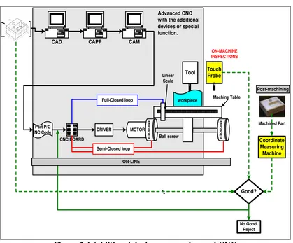
The traditional approach to controlling a displacement of CNC machine tools has been to use rotary drive motors and ball screws to achieve table motion [Gordon & Hillery, 2005]. In a more advanced CNC system, some compliant mechanical hardware devices may be employed, such as an inspection touch probe and/or an external input/output sensor (Figure 2.4).
CNC Systems, STEP-Compliant CNC and Function Blocks
Figure 2.4 Additional devices on an advanced CNC
2.2
Some Advancements of CNC Systems
The current trends are towards open architectures such as Open System Architecture for Controls within Automation systems (OSACA) [OSACA, 2006] and Open Modular Architecture Controllers (OMAC) [OMAC, 2006] and where third party software can be used at the controller, working within a standard PC operating system. Table 2.1 summarizes the Open Architecture Controller (OAC) projects by Park et al. [Park et al., 1995].
One further industrial development is the application of software controllers, where Programmable Logical Control (PLC) logic is captured in software rather than hardware. The proposed kernel software organizes and manages various control
Table 2.1 A variety of approaches to OAC [Park et al., 1995]
CNC Systems, STEP-Compliant CNC and Function Blocks
Open architecture controller
projects
Descriptions
Open System Architecture for
Controls within Automation systems (OSACA)
ESPRIT I11 project 6379
One of the largest-scale projects for OAC
Almost all of the standardization matters including network, application software as well as hardware, have been considered The Next Generation
Controller (NGC) Program
The National Center for Manufacturing Sciences (NCMS) and the US Air Force co-sponsored (1989)
Specification for an Open
Systems Architecture Standard (SOSAS)
Martin Marietta organized industry requirements
Enhanced Machine Controller
Architecture (ECA)
The next step beyond NGC/SOSAS by National Institute of Standards and
Technology (NIST)
The Chimera Carnegie Mellon University, Pittsburgh
MDARTS The University of Michigan, EECS
The HOAM-CNC Y. Altintas and W. K. Munasinghe, Annals of the CIRP
software modules dynamically by using process and resource models [Park et al., 2006]. Although it is very difficult to form a universal agreement on the definition of an open system, vendor-neutrality and component-integrability can be thought of as two fundamental features of an open system [Park et al., 2006]. There is also a requirement for open architecture to realize agile production and autonomous CNC control [Suh & Cheon, 2002]. They offered the open CNC controller for a cutting
CNC Systems, STEP-Compliant CNC and Function Blocks
machine which has a PC-based controller, a Graphical User Interface (GUI) environment, etcetera [Hace & Jezernik, 2003].
When designing an advanced CNC machine, it is important to consider the dynamics of the control, the electrical components and the mechanical structure of the machine [Jöhnson et al., 2005]. In proprietary systems, adding sensors and the software that uses them can only be done by the original manufacturer, but sometimes enhancements are simply not available [Proctor & Albus, 1997].
Gordon and Hillery introduced a CNC Controller with a Microsoft Windows-base written in C++, and the programming language/code used was MINT, which is a structured form of BASIC designed for motion control applications [Gordon & Hillery, 2005].Yuhan et al. also conducted a study on a reconfigurable model of open CNC kernel software to analyze the life-cycle of application objects and their interactions in an open-architecture CNC controller model [Yuhan et al., 2003].
Balic introduced a new CNC control unit for machining centres, with learning ability and automatic intelligent generation of part programs, which is built-in to a CNC unit as a special device on the basis of a neural network [Balic, 2004]. The reliability of a distributed program is difficult to determine [Altintas, 2000, Koren et al., 1999, Stojcev, 2000].
The major part of an advanced CNC system is a recent development in accordance with STEP/STEP-NC. It will be one part of the proposed CNC control system and there is a very thorough explanation of how it connects to the proposed futuristic STEP-NC control system [Minhat & Xu, 2008, 2009].
2.3
STEP-NC Related Research
Global research in the area of STEP-NC is highly visible via projects of a multinational collaborative nature such as the Intelligent Manufacturing System (IMS), the European ESPRIT STEP-NC project, the American “Super Model Project”, the South Carolina Research Authority (SCRA) and Rapid Acquisition of Manufactured Parts (RAMP)[Xu et al., 2006b].
CNC Systems, STEP-Compliant CNC and Function Blocks
In 1999, the European ESPRIT STEP-NC project was started by twenty industrial and academic partners. CAD/CAM (Dassault, Open Mind), control (Siemens, OSAI), machine tools (CMS), and end users (Daimler Chrysler, Volvo) in Europe formed the European STEP-NC consortium. They moved into its second phase in 2002 to further enhance the first stage systems on the feedback mechanisms of STEP-NC.
In November 2001, the IMS STEP-NC project entailed a true international package of action with research partners from European Union regions, Korea, Switzerland and the USA [IMS, 2003]. The regional coordinators were Siemens (EU), CADCAMation (Switzerland), STEP Tools Inc. (USA) and ERC-ACI (Korea). The research included technologies in the implementation and development of STEP-NC standards for different NC applications such as milling, turning, and inspection.
The “Super Model Project” project was awarded to STEP Tools Inc. in October 1999 to work with a team of sub-contractors by the name of Model Driven Intelligent Control of Manufacturing. The Industrial Review Board (IRB) includes representatives from organizations such as Boeing, Lockheed Martin, General Electric, General Dynamics Land Systems (GDLS), General Motors, Daimler-Chrysler, Gibbs and Associates and the Department of Energy [Albert, 2001a, 2001b, Hardwick, 2001].
The South Carolina Research Authority (SCRA), under the sponsorship of the National Automotive Center, US Army Tank-Automotive and Armaments Command (TACOM), co-ordinated the Stove Management System (SMS) project that defines the Suite of STEP Application Protocols and the implementation architecture for STEP-enabled parts production within commercial and defense applications [SCRA, 2004].
2.3.1
Research Work in Germany
The Institute for Control Engineering of Machine Tools and Manufacturing Units (ISW) at the University of Stuttgart, the Laboratory for Machine Tools and Production Engineering (WZL, RWTH) in Aachen, and Siemens have been the main players in the European STEP-NC project. It utilizes STEP/STEP-NC standards for
![Figure 1.1 A typical CAx chain [Minhat et al., 2009a]](https://thumb-ap.123doks.com/thumbv2/123dok/539284.62774/12.595.107.524.341.536/figure-typical-cax-chain-minhat-et-al-a.webp)