accredited by DGHE (DIKTI), Decree No: 51/Dikti/Kep/2010 63
Chaotification of Quasi-Zero Stiffness System via
Direct Time-delay Feedback Control
Qing-chao Yang1, Jing-jun Lou1, Shu-yong Liu2, Ai-min Diao1
1
Office of Research & Development, Naval Univ. of Engineering, Wuhan, China 2College of Naval Architecture and Power, Naval Univ. of Engineering, Wuhan, China
e-mail: [email protected] [email protected]
Abstrak
Makalah ini menyajikan sebuah metode chaotification berdasarkan kendali umpan-balik waktu-tunda langsung untuk sistem isolasi kuasi-kekakuan-nol. Fungsi analisis kendali umpan-balik waktu-waktu-tunda diturunkan berdasarkan teori kendali geometri-diferensial. Selanjutnya, kelayakan dan efektivitas metode ini telah diverifikasi dengan simulasi numerik. Simulasi numerik menunjukkan bahwa metode ini memiliki aspek yang menguntungkan, termasuk keuntungan pada penguatan kendali kecil, kemampuan menhindari kekacuan di berbagai macam domain parametrik dan kelayakan tinggi pada implementasi kendali.
Kata kunci: kuasi-zero-kekakuan sistem isolasi, waktu-delay kontrol umpan balik, chaotification
Abstract
This paper presents a chaotification method based on direct time-delay feedback control for a quasi-zero-stiffness isolation system. An analytical function of time-delay feedback control is derived based on differential-geometry control theory. Furthermore, the feasibility and effectiveness of this method was verified by numerical simulations. Numerical simulations show that this method holds the favorable aspects including the advantage of using tiny control gain, the capability of chaotifying across a large range of parametric domain and the high feasibility of the control implement.
Keywords:quasi-zero-stiffness isolation system, time-delay feedback control, chaotification
1. Introduction
Isolation of undesirable vibrations is a problem in many engineering structures. In the ideal case when a mass m is supported by a linear spring with stiffness k on a rigid foundation, but the efficient attenuation of vibration does not occur until a frequency of 2k/m [1-2]. This indicates that the smaller stiffness and the wider isolation region. However, small stiffness causes a large static deflection. This limitation can be overcome by adding oblique springs in order to obtain a high static stiffness, small static displacement, small dynamic stiffness, and low natural frequency. Moreover, it is possible to achieve an isolator with zero dynamic stiffness by careful choice of system parameters, the so-called quasi-zero-stiffness (QZS) mechanism [3-5]. The fact about the benefits of QZS, has given rise to a growing interest in the study of it. Application of QZS mechanisms range from space field to machinery isolation [6-8].
Over the last two decades, the utilization of chaos has been greatly interested among researchers across various disciplinary fields [9-10]. Lou et al [11-13] reported that the power of a chaotic state may present a continuous spectrum and the intensity of line spectrum could be decreased during the chaotification process. With this motivation, an important application of chaos is of improving the concealment capability of underwater object.
continuous-time system into a discrete-continuous-time system within each driving period, and there are also some difficulties in application. It is well known that an appropriate time-delay can extend a simple dynamic system into high dimensional one, making chaotification readily achievable.
With focus on the enhancement of the concealment capability of underwater object, in this paper, we shall introduce a method of time-delay feedback control to chaotify a QZS system. Numerical simulations show that this method holds the favorable aspects including the availability of chaotification across a large range of parametric domain, and the ability to use small control gain.
This paper is organized as follows. Section 2 presents the mathematical model of QZS and the dimensionless motion of system after transformation. In section3, an analytical time-delay feedback control function is derived based on differential-geometry control theory. In section4, the validity of analytical of time-delay feedback control for QZS system chaotification was verified. In section5, discussion and conclusion are given.
2. Mathematical Model of QZS System
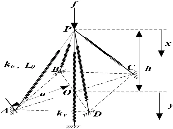
The QZS isolator considered is shown schematically in Fig.1. The system consists of a vertical spring connected at point P with four oblique springs. The vertical spring is of stiffness k1,
four oblique springs are linear with the same stiffness k2, in addition, they are pre-stressed, i.e.
compressed with
. The geometry of the system is defined by the parameters aandh
. It provided that the coordinatexdefines the displacement from the initial unloaded position. The relationship between the vertical applied force f and the resulting displacementxcan be found as Equation (1).Figure 1. A five-spring model of a QZS system
1 2
(
f
f
4
f
x)
x
0
(1)
The reaction of the vertical spring
f
1 is given by1 1
f
k x
(2)2 2
2 2
(
)
2 21
(
)
x
a
h
f
k h
x
a
h
x
(3)Combining Equations (1)-(3) gives
2 2
1
4
2(
)
2 21
(
)
a
h
f
k x
k h
x
a
h
x
(4)Provided the coordinate
y
defines the displacement from the position x=h, i.e. the static equilibrium position when the oblique springs lie horizontally, Equation (4) can be written as2 2
1 4 2 2 2 1 1
a h
f k y k y k h
a y (5)
Equation (5) can be written in non-dimensional form as
2 2 ˆ 1
ˆ ˆ 4 ˆ 1
ˆ ˆ
F y r y
a y (6) where 2 2 1
ˆ
f
f k a
h
,y y a h
ˆ
2
2,r k k
1 2,a a
ˆ
a
2
h
2,h h a
ˆ
2
h
2Differentiating Equation (6) with respect to
y
ˆ
gives the non-dimensional stiffness of the system2
3 2 2
2 2 2
ˆ
ˆ
ˆ
4
(1
)
1
ˆ
1
4 ( 1
)
ˆ
ˆ
ˆ
ˆ
(
)
ry
k
r
a
y
a
y
(7)In operation, the system is loaded with a mass such that at the static equilibrium position(
ˆ
0
y
) the oblique springs are horizontal. The stiffness of the system is zero provided thatˆ
ˆ
ˆ
4(1
)
a
r
a
(8)Assuming that displacements are small, the non-dimensional force can be expanded using the Maclaurin series up to the third order. Furthermore, taking into account the QZS condition (8), Eq.(6) can be expressed as
2 3 3
3
ˆ
ˆ
''(0)
ˆ
'''(0)
2 (1
)
ˆ
ˆ
(0)
ˆ
'(0)
ˆ
ˆ
ˆ
ˆ
ˆ
2!
3!
F
F
r
F
F
F
y
y
y
y
a
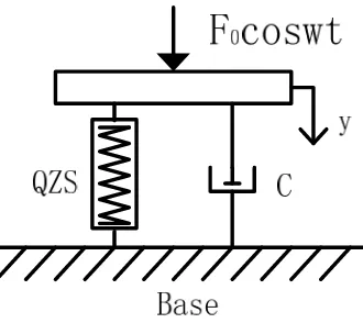
(9)To consider the influence of damping, a viscous damper with
c
2 is added in parallelwith the QZS isolator. Ideally, the system is subjected to harmonic excitation
F
0cos
wt
, the non-dimensional equation of motion can be approximated as3 ˆ
ˆ 2 ˆ ˆ cos
y
y
y F
(10)
Figure 2. Structural model of the isolator in operation
where
2
0 1
w k m,
w t
0 ,
w w
0,
cw
02
k
1,
2 (1r
ˆ) aˆ3,F F k a
ˆ
1 2
h
23. Derivation of Time-delay Feedback Control Function
In this section, an analytical time-delay feedback control function is derived based on differential-geometry control theory. We intend to present the standard procedure about how to design a time-delay controller for chaotifying the nonlinear isolation system. Based on the theory of nonlinear control, a stable nonlinear system can be exactly linearized if the relative degree of the system is exactly equal to the order of the system. The availability of the linearization implies that this method can be employed to design controller of the nonlinear system.
Based on the structure of the QZS system. Denote
y
ˆ
y
ˆ
1y
ˆ
2
T,y
ˆ
1andy
ˆ
2are the displacement and velocity of the mass.h y
( )
ˆ
is the output function of the system, and the
y t
ˆ( )
is the control function that we want to design. The controlled system can be expressed as
ˆ
( )
ˆ
( )
ˆ
ˆ
( )
ˆ
ˆ
( )
y
f y
g y
y t
z
h y
(11)
where 32
2 1
ˆ
ˆ
( )
ˆ
2
cos
y
f y
y
y
F
,0
ˆ
( )
1
g y
.1
ˆ
( )
ˆ
ˆ
2
f
g
f
ad g y
f
g
y
y
(12)
0
1
ˆ
ˆ
[
( )
( )]
2
1
2
frank g y
ad g y
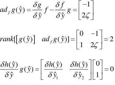
(13)1 2
0
ˆ
ˆ
ˆ
( )
( )
( )
ˆ
( )
0
ˆ
ˆ
ˆ
1
h y
h y
h y
g y
y
y
y
(14)The Eq.(14)have multiple solutions, one of the solutions is given by
1
ˆ
ˆ
( )
h y
y
(15)Therefore, we may take Eq.(16) as the control function.
1
ˆ
( )
tˆ
(
)
y
k y
t
(16)4. Dynamic Analysis of QZS System
In this section, numerical simulations will be conducted to verify the effectiveness of the time-delay feedback function for chaotifying QZS system. The effects on chaotification related of the parameters
( , )
k t
t provide clues about how to optimize controller to improve the quality ofchaotification. For the convenience, we fix the system’s parameters as follows,
0.1
,
1
,ˆ
0.5
F
,
0.6
.4.1. Effect of Feedback Control Gain
k
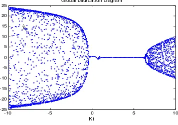
tWe now study how the feedback control gain
k
taffects the system behaviors throughbifurcation analysis. The parameters of the controller is set as
t
0.66
, andk
t is varied within theinterval of
( 10,10)
. The global bifurcation diagram of the state variabley
ˆ
2versusk
t is depicted in Figure 3.Figure 3 depicts the global bifurcation where the cloud dots correspond to chaotic or high-order harmonic motions and the line dots are related to simple periodic motion in the interval
( 0.22, 5.8)
. We can study characteristics of the system response by scanning the whole parametric domain ofk
t. The control gaink
tis associated with the control energy required for chaotification. From the Fig.3, the minimum feedback gain that provoking chaos is the value of0.23
tk
if setting the control gain in the negative parametric domain, and the minimum oneis the value of
k
t
5.9
if setting the control gain in the positive parametric domain. The tiny requirement of the minimum control gain in the negative domain make this method much attractive, since the use of small control energy is particularly desirable in practical applications.4.2. Effect of the Control Time-Delay
t
Figure 3. Global bifurcation diagram versus
k
tFigure 4. Global bifurcation diagram versus
t
-10 -5 0 5 10
-25 -20 -15 -10 -5 0 5 10 15 20 25
Kt
Global bifurcation diagram
0 5 10 15 20
-10 -8 -6 -4 -2 0 2 4 6 8 10
t
Global bifurcation diagram versus t 2
ˆ
y
2
ˆ
Figure 4 shows a bifurcation diagram to illustrate the behaviors of the QZS system when the time-delay
t
varies across a wide range of(0, 20)
. We observe that the first bifurcation occurs aroundt
1.8
. The system thereafter undergoes chaotic state as the time-delay increase. In general, it can be seen that the chaotic state widely exists in the parametric domain of(0, 20)
.5. Conclusion
In this paper, we introduced a method based on feedback time-delay control theory to the research area for a QZS system chaotification. The analytical solution of control function was derived based on differential-geometry control theory. Furthermore, the feasibility and the effectiveness of this method was verified by numerical simulations. Through the study of the control parameters of the control gain and time-delay, we know that chaotification is possible when control gain and time-delay exceeds a threshold. The most favorable feature we found is the availability of using tiny control for chaotification, the accessibility of chaotification to a wider parametric domain and the high feasibility of the control implement, these factors make this method greatly attractive to applications.
Acknowledgements
This research work was supported by the National Natural Science Foundation of China(51009143, 51179197).
References
[1] C.M. Harris, A.G. Piersol. Shock and Vibrations Handbook. New York: McGraw Hill. 2002. [2] E.I. Rivin. Passive Vibration Isolation. New York: ASME Press. 2001.
[3] A. Carrella, M.J. Brennan, T.P. Waters. Static Analysis of a Passive Vibration Isolation with Quasi-zero-stiffness Characteristic. Journal of Sound and Vibration. 2007; 301: 678-689.
[4] Ivana Kovacic, Michael J.B Rennan, Timothy P. Waters. A Study of a Nonlinear Vibration Isolation with a Quasi-zero-stiffness Characteristic. Journal of Sound and Vibration. 2008; 315: 700-711. [5] J. Zhang, D.Li, S. Dong. An Ultra-low Frequency Parallel Connection Nonlinear Isolator for Precision
Instruments. Key Engineering Materials. 2004; 257: 231-236.
[6] K. Denoyer, C. Johnson. Recent Achievements in Vibration Isolation Systems for Space Launch and on-Orbit Application. 52nd International Astronautical Aongress. France: Toulouse. 2001.
[7] J. Dankowski. State of the Art Vibration Isolation of Large Coordinate Measuring Machine With an Adverse Environment. 2nd Euspen International Conference. Turin, Italy. 2001.
[8] J. Winterflood. High Performance Vibration Isolation for Gravitational Wave Detection. PhD Thesis. University of Western Australia-department of Physics; 2001.
[9] Chen GR, Mao YB, Chui CK. A Symmetric Image Encryption Scheme Based on 3D Chaotic Cat Maps. Chaos, Solitons & Fractals. 2004; 21:749-761.
[10] Freeman WJ, Chaos in the Brain. Possible Roles in Biological Intelligence. International Journal of Intelligent Systems. 1995; 10: 71-88.
[11] Lou JJ, Zhu SJ, He L, Yu X. Application of Chaos Method to Line Spectra Reduction. Journal of
Sound and Vibration. 2005; 286: 645-652.
[12] Zhang ZH, Zhu SJ, He QW. Multi-line Spectra Reduction of Vibration Isolation System Based on Chaotification Method. Journal of Vibration Engineering. 2012; 25: 30-37.
[13] Yu x, Zhu SJ, Liu SY. A New Method for Line Spectra Reduction Similar to Generalized Synchronization of Chaos. Journal of Sound and Vibration. 2008; 3: 855-864.
[14] Li GH, Sun XN. Projective Synchronization in Chaotic Systems based on Observer. Chinese Journal
of Quantum Electronics. 2006; 23: 677-680.
[15] Tao HF, Fu SS. Time-delay Generalized Projective Synchronization of Piecewise Chaotic System With Unkown Parameters. Acta Phys.Sin. 2011; 60: 0105141-0105146.
[17] Li ZB, Zhao XS, Wang J. Generalized Projective Synchronization of Chaotic Systems via Modified Active Control. Acta Phys.Sin. 2011; 60: 0505081-0505088
[18] Konishi K. Making Chaotic Behavior in a Damped Linear Harmonic Oscillator. Physics Letters A. 2001; 284: 85-90.
[19] Konishi K. Generating Chaotic Behavior in an Oscillator Driven by Periodic Forces. Physics Letters A. 2003; 320: 200-206.