UNIVERSITI TEKNIKAL MALAYSIA MELAKA
FAKULTI KEJURUTERAAN ELEKTRIK
FINAL YEAR PROJECT 2
BEKU 4894
2013/2014
FINAL YEAR PROJECT REPORT
SPEED AND TORQUE CONTROLS
OF BRUSHLESS DC MOTOR
NAME : MUHAMMAD ADIB BIN MD ROHIM MATRIC NO : B 011010055
COURSE : 4 BEKE
SUPERVISOR: DR. AUZANI BIN JIDIN
SPEED AND TORQUE CONTROLS OF BRUSHLESS DIRECT CURRENT MOTOR
MUHAMMAD ADIB BIN MD ROHIM
A report submitted in partial fulfilment of the requirements for the degree
of Bachelor of Electrical Engineering (Power Electronic and Drives)
Faculty of Electrical Engineering
UNIVERSITI TEKNIKAL MALAYSIA MELAKA
APPROVAL
“I hereby declare that I have read through this report entitle
“SPEED AND TORQUE CONTROLS OF BRUSHLESS DIRECT CURRENT MOTOR” and found that it has comply the partial fulfilment for awarding the degree of
Bachelor of Electrical Engineering (Power Electronic and Drives)”.
Signature : ... Supervisor’s Name : Dr. AUZANI BIN JIDIN
DECLARATION
I declare that this report entitle “SPEED AND TORQUE CONTROLS OF BRUSHLESS
DIRECT CURRENT MOTOR” is the result of my own research except as cited in the references. The report has not been accepted for any degree and is not concurrently submitted
in candidature of any other degree.
ACKNOWLEDGEMENT
I would like to express my deepest appreciation to all those who provided me the possibility to complete Final Year Project (FYP). I take this opportunity to express my profound gratitude to my supervisor, Dr. Auzani Bin Jidin for his guidance and constant encouragement throughout the completion of this thesis.
Besides, I am highly indebted to Muhd Khairi Bin Abd Rahim and Adeline Lukar Herlino for their guidance and ideas as well as for providing necessary information regarding this project. A special gratitude also I give to my course mates whose has help me a lot and supporting me through the project. Not to mention both my panels, Mdm. Norhazilina Binti Bahari and Dr. Fazlli Bin Patkar for their time and effort to evaluate my thesis.
ABSTRACT
ABSTRAK
TABLE OF CONTENTS
CHAPTER 2 LITERATURE REVIEW ... 5
2.1 Introduction ... 5
2.2 Basic Topologies ... 5
2.2.1 Construction of BLDC Motor ... 5
2.2.2 Operation Of BLDC Motor ... 7
2.2.3 Stator Winding Variants ... 9
2.2.4 Hall Effect Sensors ... 9
2.3 Related Previous Work... 11
2.3.1 Topologies Of Control Strategy For BLDC Motor ... 11
2.4 Summary Of Review ... 18
CHAPTER 3 METHODOLOGY ... 19
3.1 Introduction ... 19
3.2 Modelling Of Brushless DC Motor ... 20
3.3 PI Controller ... 22
3.3.1 Proportional Parameter ... 22
3.3.2 Integral Parameter ... 23
3.4 Proportional (Kp) and Integral (Ki) Gains Tuning... 24
3.5 Hysteresis Current Switching Control... 24
3.6 Hall Effect Sensor ... 25
3.7 Torque Loop Of Experiment And Simulation... 27
3.8 Experimental Speed Loop Test ... 27
3.9 Analytical Approach ... 28
3.9.1 Proposed Simulation Algorithm ... 28
3.9.2 Experimental Setup ... 29
3.10 Conclusion ... 32
CHAPTER 4 RESULT AND DISCUSSION ... 34
4.1 Introduction ... 34
4.2 Parameters Setting ... 35
4.3 Simulation Results Of Hall Effect Decoded Signals ... 36
4.4 Simulation Of Reference And Actual Currents... 39
4.5 Torque Test ... 41
4.6 Low-High Speed and Reverse-Forward Speed ... 43
4.7 Overshoot and Low Dynamic Response ... 47
CHAPTER 5 CONCLUSION... 49
REFERENCES ... 51
LIST OF FIGURES
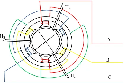
Figure 2. 1 : Cross section of BLDC motor with respect to Hall Effect Sensor ... 6
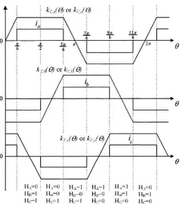
Figure 2. 2 : Ideal back-emf’s, phase currents, and Hall Effect signals ... 7
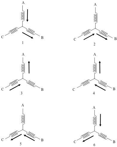
Figure 2. 3 : Winding energizing sequence ... 8
Figure 2. 4 : PI speed controller block diagram ... 14
Figure 2. 5 : Fuzzy Logic System ... 16
Figure 3. 1 : Three phase equivalent circuit and mechanical model of BLDC machine ... 20
Figure 3. 2 : Hysteresis current control block diagram ... 25
Figure 3. 3 : Hysteresis current control ... 25
Figure 3. 4 : Voltage source inverter (VSI) ... 26
Figure 3. 5 : Structure of Speed Loop of Torque Hysteresis Controller for BLDC motor ... 28
Figure 3. 6 : Experimental set-up ... 29
Figure 3. 7 : Simulation Torque Loop of Torque Hysteresis Control for BLDC motor ... 30
Figure 3. 8 : Simulation Speed Loop of Torque Hysteresis Control for BLDC motor... 31
Figure 3. 9 : Flowchart of the project ... 33
Figure 4. 1 : Waveforms of rotor angle, Hall Effect signals and Decoded Hall Effect signals ... 36
Figure 4. 2 : Subsystems of the decoder ... 37
Figure 4. 3 : Hall Effect signals ... 38
Figure 4. 4 : Decoded Hall Effect signals ... 38
Figure 4. 5 : Waveform of reference currents ... 39
Figure 4. 6 : Waveform of actual currents ... 40
Figure 4. 7 : Comparison between experiment and simulation results ... 42
Figure 4. 9 : Comparison of experiment and simulation results for speed transition from
-30 rad/s to 30 rad/s (Reverse Forward) 46
LIST OF TABLES
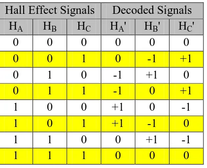
Table 2. 1 : Hall Effect decoded signals ... 10
Table 2. 2 : Rule Base of Fuzzy Logic... 17
Table 3. 1 : PI value setting ... 24
Table 3. 2 : Switching sequence ... 26
Table 3. 3 : Decoded signals and motor phase current ... 26
Table 4. 1 : Parameters of BLDC motor ... 35
Table 4. 2 : Control system parameters ... 35
Table 4. 3 : Hall Effect truth table ... 37
Table 4. 4 : Load parameters ... 41
Table 4. 5 : Torque test results ... 41
Table 4. 6 : PI controller gains set up for Low-High operation ... 43
Table 4. 7 : PI controller gains set up for Reverse-Forward operation ... 45
CHAPTER 1
INTRODUCTION
1.1 Project Background
For decades, Direct Current (DC) motors served in many applications. It is due to the simplicity of its construction, controlling mechanism, and can produce superior dynamic performance. Despite of that, the construction of DC motor that equipped with brushes and commutator can cause some limitations. Furthermore, due to the existence of the brushes and commutator, it requires regular maintenance, cannot operated at very high speed, and usually reduce the life expectancy of Brushed DC (BDC) motor. Thus, the Brushless DC (BLDC) motor were developed to overcome deficiency of the Brushed DC motors.
DC motors were known for their efficiency and reliable characteristics that are suitable for many applications. Unlike AC motors, DC motors able to operate at a fixed speed for a fixed voltage. Yet, one of the conventional DC motors is Brushed DC motor have many drawbacks on its mechanical compartments. It requires both brushed and commutator for its operation where its limit the capabilities of the motor. Thus, the BLDC motors is proposed to overcome the drawbacks of conventional dc machines.
1.4 Scope Of Project
The main scope of this project is to control Speed and Torque for BLDC motor using PI speed controller and Torque Hysteresis Controller respectively. This project is proposed to improved the speed performance by selecting appropriate values of Kp and Ki gains. Besides, it is important to develop the model of BLDC motor for further understanding. Next, for the final stage of the project, the simulation model of Speed and Torque Controls for BLDC motor using MATLAB/SIMULINK must be analyse and compared with experimental result to verify the efficiency of the scheme. The experiment was conducted using iDRIVE controller that equipped with dSPACE, Voltage Source Inverter (VSI), Gate Driver, Decoder, and Current Transducer.
1.5 Report Outlines
Chapter 1 is mainly about defining the objectives and scope of the project. All the consideration have been taken into account to ensure the project achieved the objectives. The project background and motivational project also been discussed in this chapter. This is the most important part to ensure that the vision of the project is clearly understood.
In chapter 2, a brief literature review has been done to study the theoretical views of the machines used and all the related previous works. Besides, the construction and operation of the BLDC motor also been analysed. Lastly, all the conventional control techniques has been study to ensure a better understanding on the executed project.
from the simulation and experiment were analyse to observe its performance. The characteristic of the results will indicates either it has obtained the desired output of the proposed control scheme.
CHAPTER 2
LITERATURE REVIEW
2.1 Introduction
This chapter is generally about to study and analyse the related information and previous works on the related topics. It is compulsory to fully understand the theoretical and concepts of both BLDC motor and drives to ensure that the project can accomplished and meet the objectives.
2.2 Basic Topologies
2.2.1 Construction of BLDC Motor
windings but generally it were designed in single phase , two phase, and three phase configurations. However, three phase configuration motors connected in star connection are the most popular and widely used due to its efficiency and low torque ripple. Theoretically, the higher the number of phase windings will improve the electromagnetic torque quality but infinite number of phase windings is not appropriate in practice[2].
As mentioned, BLDC motors did not consists of commutator and brushed as BDC motors to operate. This motor requires controller that is an electronic commutation in order for it to supply commutated current to the motor windings synchronized to the rotor position[4]. As the magnetic field at the stator will change due to the current polarity changes in the slots windings. Thus, the current polarity must change accordance to the rotor magnetic field which requires the rotor position to be traced[3]. In order to specify the rotor position, a feedback position sensor is readily mounted or embedded in the BLDC motor that is known as Hall Effect sensor. Hall sensor used to detect the rotor position in order to determine which stator winding that will be energized in proper sequence[1]. The cross section of BLDC motor with respect to the embedded Hall Effect sensor.
C
2.2.2 Operation Of BLDC Motor
The BLDC motor is constructed by a three phase star connection windings and ungrounded neutral point[5]. However, it operated as if it is designed in two phase connection. Depending on rotor position, only two of the inverter legs will be energised at particular time[6]. Where, the third leg is kept inactive at the same time. Each sequence shown in Figure 2.3 rotates at 60 electrical degrees. One full 360 degree rotation six step voltage source inverter need 6 sequence with only one current path for each sequences[7]. In Figure 2.2 below shows the correlative of back emf, phase currents, and Hall effect signals relatively.
1 2
C B
A
3
B C
C B
C B
A
6
C B
A
4
C B
A
5
2.2.3 Stator Winding Variants
2.2.3.1 Trapezoidal Motors
As the name indicate, the trapezoidal motor produce a back Electro Motive Force(EMF) in trapezoidal shape. In addition, due the trapezoidal shape of the induced back EMF in the stator winding, its phases needs to be supplied with quasi-square currents for ripple-free torque operation. Even though the torque output produce by sinusoidal motors smoother than a trapezoidal motor, but it can gives higher efficiency, torque output is constant and proportional to currents amplitude, simple and lower cost. It also has been chosen as the motor that to be used in the project.
2.2.3.2 Sinusoidal Motors
Whereas for sinusoidal motors, it requires sinusoidal phase current for ripple-free torque operation as it generates sinusoidal shaped of the back EMF. Despite of its smooth torque output, it comes with several drawbacks because requires complex software and hardware compare to trapezoidal motors. Besides, the rotor position should be detected at every time instant, thus it should be equipped with high resolution position sensor.
2.2.4 Hall Effect Sensors
should be energize for the next sequences.
Mostly, in each of BLDC motors are mounted with three Hall sensors in the stator at the non-driving end of the motor. The sensors are placed with equal distance from one another by 60 electrical degrees to ensure that each sensors output is aligned with either one of the electromagnetic circuit[8]. A digital high level for the first 180 electrical degrees of electrical rotation will be produce while the rest of 180 electrical degrees will outputs a low level[8]. This digital levels are generate by each of the sensor elements. The Hall sensor will interpreted either high or low signal each time when the rotor magnetic poles pass near the sensors. Thus, this process will show either North or South pole that is passing close to the sensors.
However, the signals that are either low or high must be decoded to respected signals as shown in Table 2.1. Only then, the decoded signals can generate the reference current that will be used for the control scheme.
2.3 Related Previous Work
2.3.1 Topologies Of Control Strategy For BLDC Motor
This section will discussed about the schemes that applicable for BLDC machine. All the concepts and operation works being compared to each other for better understanding on controlling BLDC motor.
2.3.1.1 Voltage Control
Voltage control strategy implement the theory that speed of BLDC motor is directly proportional to the voltage applied to the motor terminals[3]. The speed of the BLDC motors are achieved by varying the voltage source that supplied to the motor. As the higher the voltage source, the faster the speed of the motor. This control strategy did not consist any current control loop, hence there are no current sensors used in the drive. Besides, this strategy is less cost compared to pulsed power stage which is the PWM. However, a linear power stage gives out high losses at high current and low voltage.
2.3.1.2 PWM Control
circumstances.
However, in practice, the load will be resistive-inductive. As any case, when the current passing the inductors, it is forced toward zero in a short time, inductive load may damage the switches and resulting very high voltage spikes[3]. Thus, it needs a diode labelled as free wheeling diode to eliminate the high voltage spikes by allowing the current to naturally go down towards zero. This add the drawbacks of the PWM.
PWM approaches in producing signals are by comparing the voltage control with a sawtooth carrier signal. The switching signal describes as follow:
Switching signal =
2.3.1.3 Torque Hysteresis Control
In Torque Hysteresis Control (THC) strategy, there will be one current control loop for the structure. The control scheme implement inner current control loop by using DC link current[6]. Two of the three phase currents were measured and then fed to the DC link current. By doing this, the reference currents can be generated. However, it is important to ensure that the sum of phase currents is zero to enable this concept being used. This method suits the BLDC motor because it is designed with three phase star connection with an ungrounded neutral point. Using this scheme, an efficient and high torque dynamic response of the electric machines can be achieved. Besides, the advantage of using this technique is that from the phase currents, the torque were directly determined[1]. The production of DC link current and torque are given as in equation 2.1 and equation 2.2 respectively.