i
“I hereby admit that have read this report and from my point of view this report is
enough in term of scope and quality for purpose for awarding
Bachelor of Degree in Mechanical Engineering (Thermal-Fluid)”
Signature
: ……….
Supervisor Name I : ……….
Date
: ……….
Signature
: ……….
Supervisor Name II : ……….
HEAT TRANSFER CHARACTERICSTIC OF A CONDENSERWITH Al2O3
REFRIGERANT BASED NANOFLUIDS AS WORKING FLUID
NICHOLAS LIAN AK MUJAH
This report presented to fulfill the requirement in term to obtain
Bachelor of Degree in Mechanical Engineering (Thermal-Fluid)
Fakulti Kejuruteraan Mekanikal
Universiti Teknikal Malaysia Melaka
ADMISSION
“I admit this report has been written by me myself except for some quotation that has
been noted well for each of them”
Signature
:……….………
Author Name :……….………
DEDICATION
This report is dedicated to my beloved parents
Mujah @Tumbin ak Enjawan
and
APPRECIATION
First of all, thanks God for His almighty that I can complete this report. Thus,
thanks also to my beloved parents that always support me although they are far away
from me. Special thanks to my supervisor, Pn. Fadhilah bt Shikh Anuar in guiding me
along this report writing and project computation.
ABSTRACT
ABSTRAK
TABLE OF CONTENTS
CHAPTER
PAGE
ADMISSION
i
DEDICATION
ii
APPRECIATION
iii
ABSTRACT
iv
ABSTRAK
v
TABLE OF CONTENTS
x
LIST OF TABLES
xii
LIST OF FIGURES
xii
CHAPTER 1
1
INTRODUCTION
1
1.1 Background Study
2
1.2 Objectives
2
1.3 Scope
3
1.4 Problem Statement
3
CHAPTER 2
4
LITERATURE RIVIEW
4
2.1 Refrigeration System
4
2.2 Component of Refrigerant System-Condenser
6
2.3 Nanorefrigerant
7
2.4 Thermal Conductivity of Nanorefrigerant
11
2.5 Pressure Drop of Nanorefrigerant
25
CHAPTER 3
36
METHODOLOGY
36
3.1 Introduction
36
3.2 Design and Physical Properties of Condenser
37
3.3 Mathematical Modeling
39
3.3.1 Thermal Conductivity
39
3.3.2 Pressure Drop
40
3.3.3 Heat Transfer
41
3.4 Simulation using CFD
42
3.4.1 Simulation set ups
42
CHAPTER 4
44
RESULTS AND DISCUSSION
44
4.1 Introduction
44
4.2 Calculations Result
45
4.2.1 Thermal Conductivity
45
4.2.2 Pressure Drop
46
4.2.3 Heat Transfer rate
48
4.3 Simulation Data
49
4.3.1 Thermal Contours
49
4.3.2 Pressure contours
52
4.3.3 Heat Transfer rate
52
4.4 Discussions
54
4.4.1 Surface Area Impact
54
4.4.2 Interfacial Layer Impact
55
4.4.3 Brownian motion
56
4.5 Different between simulation and calculation data
57
CHAPTER 5
36
CONCLUSION AND RECOMMENDATIONS
58
5.1 Conclusion
58
REFERENCES
60
APPENDIXES A Gantt chart
62APPENDIXES B
FLUENT ANSYS simulation
72APPENDIXES C Workbenches Schematic
72APPENDIXES D Thermal conductivity enhancement percentage
(calculation)
73
LIST OF TABLES
TABLE
CONTENTS
PAGE
Table 2.1 The selective summary of the thermal conductivity enhancement
in Al2O3-based nanofluids
15
Table 2.2 Summary of experiment on convective heat transfer of nanofluids
32
Table 3.1 Physical properties of Al2O3 nanoparticles and refrigerant, R-134a
38
Table 3.2 Constant perimeters
38
Table 3.3 Simulation steps
42
Table 4.1 Thermal Conductivity Data
45
Table 4.2 Pressure Drop Data
47
Table 4.3 Heat Transfer Data
48
Table 4.4 Temperature Contours
49
LIST OF FIGURES
FIGURES
CONTENTS
PAGE
Figure 2.1 Aluminum oxide particles, Al2O3
9
Figure 2.2
Cooper oxide particles, CuO
9
Figure 2.3
Comparison of some experimental data on thermal conductivity
for aluminum oxide
14
Figure 2.4
Comparison of the experimental nanoparticle impact factors with
the predicted values by the nanoparticle impact factor equation
27
Figure 2.5 Laminar flow heat transfer comparison.
34
Figure 2.6 Laminar flow heat transfer comparison for different L/D values.
34
Figure 2.7 Nusselt number vs. Reynolds number in laminar flow.
35
Figure 2.8 Effect of volume fraction on Nusselts number.
35
Figure 3.1
Project flowchart
37
Figure3.2
Horizontal smooth tube condenser
38
Figure4.1
Thermal Conductivity versus Volume Fraction graph
45
Figure4.2
Pressure Drop versus Volume Fraction graph.
46
Figure4.3
Heat Transfer Vs Volume Fraction.
48
Figure4.4
Pressure Contours
52
Figure4.5
Comparison between calculations and simulations heat transfer
data.
52
Figure4.6
Rubik Cubes
54
Figure4.7
Schematic cross section of nanofluid structure consisting of
nanoparticles, bulk liquid, and nanolayers at solid/liquid interface
NOMENCLATURE
A
Area(
m2)
x
B
2Depolarization factor along x- symmetrical
axis
c
constant
p
C
Heat capacity(
J/kg.K)
d
Diameter (m)
f
friction
h
Heat transfer coefficient(
W/m2K)
k
Thermal Conductivity (
W
/
m
.
K
)
c
k
33Longitudal equivalent thermal conductivity
c
k
11Transverse equivalent thermal conductivity
L
Length (m)
Nu
Nusselt number
Pr
Prandtl number
Re
Reynold number
r
Radius (m)
T
Temperature (
oCor K)
T
Temperature difference
U
Overall heat transfer coefficient (
W/m2K)
Greek Symbols
Volume ratio
Particle motion
n
Shape factor
Density (
kg
/
m
3)
Volume Fraction
Ratio of nano layer
Elliptical complex nanoparticles
v
Velocity(
m
/
s
)
Viscosity(
Pa
.
s
)
Particle sphericity
Subscripts
p
Nanoparticles
b
Base fluid
eff
Effective
pe
Modified
in
Inlet
1
CHAPTER 1
INTRODUCTION
1.1
Background Study
An air conditioner is a mechanism designed to extract heat from an area. The
whole process is done using the refrigerant cycle. The process consists of heating,
ventilation and air conditioning or usually referred as HVAC. HVAC is a form of air
treatment whereby temperature, ventilation and cleanliness are all controlled within
limits determined by the requirements of the air conditioned enclosure. In the HVAC
system, refrigerant is used.
A refrigerant is a substance used in air conditioning system. Usually,
fluorocarbons, especially chlorofluorocarbons, were used as refrigerants, but now they
are illegal because of their ozone depletion effects. Other common refrigerants used in
various applications are ammonia, sulfur dioxide, and non-halogenated hydrocarbons
such as methane.
2
needs.. For example, a refrigerator uses a condenser to get rid of heat extracted from the
interior of the unit to the outside air. Condensers are used in air conditioning, industrial
chemical processes such as distillation, steam power plants and other heat-exchange
systems. Use of cooling water or surrounding air as the coolant is common in many
condensers.
Nanorefrigerant might still a new technology out there. However, this technology
has a big potential to be commercialized as the result to its advantages. One of the
applicable nanotechnologies is nanofluid. Nanofluid is a mixer between nanoparticles
and based fluid. Examples of nanoparticles such as aluminum oxide, cooper oxide and
carbon nanotubes. While base fluids are such as DI water, ethylene glycol, and oil. The
nanoparticles suspense into any refrigerant called as nanorefrigerant in the refrigerant
system. This is regarding its benefits to enhance the performance of the refrigeration
system. When a substance in nano sized, it‟s actually change its properties and
somehow, it can benefit air conditioning system. Thus, because of that, nanofluid can
actually revolutionize the air conditioning system by introducing nanorefrigerant as the
new working fluid to replace the conventional base fluids.
1.2
Objectives
1)
To investigate the effect of aluminum oxide nanoparticles with volume fraction
from 0.2 to 1.0 vol % on thermal conductivity of nanorefrigerant.
2)
To study the effect of the nanoparticle volume fraction on pressure drop of the
nanorefrigerant.
3
1.3
Scope
This study will use mathematical modeling to investigate and determine the
thermal physical properties of the nanorefrigerant. The parameters such as size of
nanoparticles, types of refrigerant, nanorefrigerant velocity, and mass flux, heat flux
are constants. The only variable in this study is only the nanoparticle volume
fraction.
1.4
Problem Statement
4
CHAPTER 2
LITERATURE REVIEW
2.1
Refrigeration System
The refrigeration cycle is the series of events that occur to allow the refrigerant
to both absorb and release heat energy. The refrigeration system is divided into
low-pressure side and high-low-pressure side. There are two specific points within the
refrigeration system where the system divides: the compressor and the metering device.
The high side of the system begins with the compressor outlet and includes the
condenser and associated lines and ends at the metering device inlet. The low side of the
system begins at the outlet of the metering device and includes the evaporator and
associated lines and end sat the compressor (Cengel, 2006).
5
the pressure applied. High-pressure, high-temperature refrigerant vapor exits the
compressor and travels through the discharge line to the condenser. (Cengel, 2006)
When the refrigerant reaches the condenser inlet, it is almost 100 percent vapor.
A small amount of liquid may remain. As the refrigerant moves from the top of the
condenser, it passes through the tubes. Much of the heat that is present within the vapor
is transferred to the tubes and fins of the condenser. As air moves across the surface of
the fins and tubes, heat is dissipated into the atmosphere. This process is aided by a ram
air effect provided by the movement of the vehicle and the operation of the cooling fan.
As the refrigerant moves down through the tubes on the condenser, much of the latent
heat stored in the vaporized refrigerant is released, causing the vapor to condense into a
liquid. (Carrigan et. al, 2006)
High-pressure liquid refrigerant exits the condenser into the liquid line, where it
is transported to the metering device. The metering device acts as a restriction, reducing
the amount of refrigerant pressure and volume. As the liquid passes through the
metering device, the pressure is reduced by approximately 75 percent or more. Because
pressure and temperature are relative to one another, the temperature of the refrigerant is
significantly reduced as the refrigerant exits the metering device. The refrigerant exits
the metering device as a low-pressure, low-temperature liquid. (Carrigan et. al, 2006)
6
and is transported to the compressor. At this point, the cycle starts over (Carrigan et. al,
2006).
2.2
Component of Refrigeration System – Condenser
The condenser is the next destination for the refrigerant after it leaves the
compressor. When the refrigerant leaves the compressor and enters the condenser, it
does so as a high-pressure, high-temperature vapor. The purpose of the condenser is to
remove enough heat from the gaseous refrigerant to cause a change of state into a
high-pressure liquid (Cengel, 2006).
The condenser is a heat exchanger is physically located at the front of the vehicle
and install in front of the radiator. The placement of the condenser allows for maximum
airflow to pass the condenser to provide maximum heat transfer (Cengel, 2006).
7
2.3
Nanorefrigerant
Refrigeration is very important nowadays especially in a country like Malaysia.
Since Malaysia is considered as hot country, thus chilling system is a must in their
households, offices and etc. However, the use of refrigeration system is quite a waste in
terms of energy. This is because, a refrigeration cycle required a lot of energy compared
to any electrical items such as lamps, and fans.
Refrigerants are the transport fluids which convey the heat energy from the
low-temperature level to the high-low-temperature level, where it can, in terms of heat transfer,
give up its heat. In the broad sense, gases involved in liquefaction processes or in
gas-compression cycles go through low-temperature phases and hence may be termed
“refrigerants,” in a way similar to the more conventional vapor-compression fluids.
Refrigerants are designated by number. The identifying number may be preceded
by the letter R, the word “Refrigerant,” or the manufacturer‟s trademark or trade name.
The trademarks or trade names shall not be used to identify refrigerants on equipment or
in specifications. In the previous time, chlorofluorocarbon (CFC) and hydro
chlorofluorocarbon (HCFC) are use as refrigerant in air conditioning system. However,
due to the “greenhouse effect”, these refrigerants have been phase out.
Nowadays, new refrigerants, primarily hydrofluorocarbon, HFCs, have been
commercialized to replace them. There has also been a renewed interest in non
halocarbon refrigerants such as ammonia and carbon dioxide.
8
and development have been proposed to improve the heat transport properties of fluids.
At the beginning, researchers tried to blend or suspend the base fluid with solid particles
of micrometer, even millimeter magnitudes to increase the thermal conductivity of the
base fluid since the thermal conductivity of solid is typically higher than that of liquids
(Xiang and Mujumdar, 2006). Based on their research, they able to increase the thermal
conductivity of cooper up to 401 W/m.K and aluminums up to 237 W/m.K. Those are
metallic materials. For non-metallic, silicon and alumina, Al2O3, the thermal
conductivity increase up to 148 W/m.K and 40 W/m.K respectively. Others are metallic
liquid such as sodium and non-metallic liquid such as water, which were also enhanced
in terms of its thermal conductivity. However due to its large density and size,
practically it the applications are limited. Furthermore, by using micro particles, it may
cause abrasion of the surface, clogging the micro channels and increasing the pressure
drop (Zenghu Han et al, 2008).
Regarding this issues, researchers and scientists put one step forward.
This time they consider nanotechnology. Thus, it is leading to process and produce
materials with average crystallite sizes below 50 nm. Fluids with nanoparticles
suspended in them are called nanofluids, a term proposed by Choi in 1995 at the
Argonne National Laboratory, U.S.A. (Choi et al.1995).
9
phase (nanoparticles) are extremely tiny, which can be very stably suspended in fluids
with or even without the help of surfactants ( Xuan and Li, 2003).
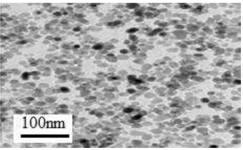
Researchers usually use nanoparticles such as aluminum oxide, Al2O3 and
Cooper oxide, CuO in their research. Figure 2.1 and Figure 2.2 are the pictures of those
particles that mentioned above;
Figure 2.1 Aluminum oxide particles, Al2O3.(Xuan et. al 2003).
Figure 2.2 Cuprum oxide particles, CuO (Vegalapudi, 2008).
10
Based on Wu et al. (2008) investigation on the boiling heat transfer
characteristics of nanorefrigerant are focused only on the pool boiling heat transfer and
there are no published researches on the flowing boiling heat transfer characteristics of
nanorefrigerant according to Peng et al. (2009).
In recent years, Park and Jung (2007 a, b) conducted an experiment on the pool
boiling heat transfer of CNT‟s/R22, CNT‟s/R123 and CNT‟s/R134a using horizontal
smooth tube. The result was quite shocked because at lower heat flux, the enhancement
of the heat transfer coefficients became clearer and the maximum enhancement could
reach 36.6%. The results of the experiment also showed that the pool boiling heat
transfer coefficients of refrigerants improved by using CNT‟s.
11
2.5
Thermal Conductivity of Nanorefrigerant
Generally, thermal conductivity is the property of a material which is its
ability to conduct heat. Heat transfer by conduction involves transfer of energy
within a material without any motion of the material as a whole. Conduction
happened when a temperature difference exists in a solid medium. Conductive
heat flow occurs when temperature is decreasing because higher temperature
generates higher molecular energy or more molecular movement. Energy is
transferred from the more energetic to the less energetic molecules when
neighboring molecules collide among themselves. In terms of unit, in
International System of Units (SI), thermal conductivity measured by watts per
meter Kelvin (W/m .K).
Murshed et al. (2007) stated that the thermal conductivity of nanofluids
varies with three attributes; size, shape and material of nanoparticles. For
example, nanofluids that are suspended with metallic nanoparticles were found to
have a higher thermal conductivity than nanofluids that are suspended with
non-metallic (oxide) nanoparticles. Furthermore, nanofluids that are suspended with
nanoparticles that are spherical in size increased only a smaller value of thermal
conductivity compared with the nanofluids having cylindrical (nano-rod or tube)
nanoparticles.