IEEE Student Conference on Research & Development 2013
Investigation of Hybrid Energy Harvesting Circuits
Using Piezoelectric and Electromagnetic Mechanisms
Noraini Mat Ali, Ain Atiqa Mustapha, Kok Swee Leong Member, IEEE
Faculty of Electronic and Computer Engineering Universiti Teknikal Malaysia Melaka
Hang Tuah Jaya, 76100 Durian Tunggal, Melaka, Malaysia
Abstract- In this paper, a performance energy harvester generator with different configuration is determine by observed the output power and voltage charging of each configuration. The configuration consists of 4 structures. The first structure consists of single piezoelectric cantilever. The second consists of copper coil with approximately 1000 turns and four magnets are configured in opposite polarities at the end of the cantilever beam. The third structure configure in parallel using the same piezoelectric and electromagnetic generator. The last structure is in the series configuration. All the structure is connected with the single rectifier and the same storage system. It was found that, power generation of single PZT can generated optimum output up to 27.56mWatt and 3.44V charging voltage.
Keywords: Electromagnetic, Piezoelectric, Series configuration, Parallel configuration, Output power, Voltage Charging
I. INTRODUCTION
With the evolution of low power electronics, the dependencies on batteries as a power source has decreased by considering the lifespan, cost and function capability[1]. Thus, energy harvesting technique which promises a better lifetime and capability has replaced the use of battery as well. Energy harvesting can be defined as a process of extracting energy from ambient sources and converted into electrical energy [2].
Although there are various of ambient sources, vibration energy has attracted interests of researcher largely due to its availability which almost exits in household electrical appliances, vehicle and machineries [3,4]. In order to enhance the output power from vibration energy, hybrid energy harvester is proposed which combines piezoelectric and electromagnetic micro-generator .[5,6,7,8]. This technique allowed to collect energy from numerous sources to meet the power requirement.
In this study, the output power generated from a single source is comparing with a hybrid system. The four harvester subsystems are construct to investigate the efficiency of
hybrid system of piezoelectric (Piezo) and
electromagnetic(EM) in the same rectifier and storage system. The hybrid system is configure with series and parallel connection.
In this work, the fix frequency about 76.2Hz is used with varying load resistance by increasing gradually. The investigation results are analyzed and summarized in term of output power and voltage charging with time.
II. DESIGN CONFIGURATION
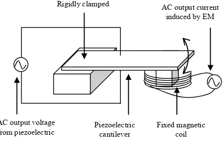
In this research, the piezoelectric and electromagnetic are constructed in same housing but with two separated energy harvesting circuit entities to power up the same device in the systems as shown in Fig. 1. The advantage of piezoelectric is able to generate relatively high voltage output which can compliment lower voltage output electromagnetic generator but with relative high current output. This is to optimize the performance of the energy harvesting system.
Fig. 1: Schematic diagram of hybrid piezoelectric and electromagnetic micro-generators
In order to verify the performance of hybrid system harvester, it is feasible to construct piezoelectric-electromagnetic in series and parallel configuration which can be compared together with individual performance of piezoelectric and electromagnetic by varying the resistance load.
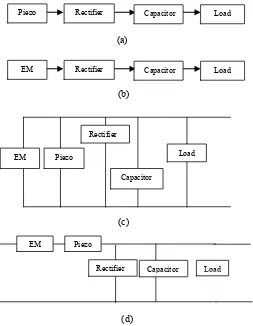
Energy harvesting output power is determined through four structures as shown in Fig 2. Structure (a) consists of PS1-5A43 piezoelectric cantilever which is clamped at the center of a shaker stand. Structure (b) consists of copper coil with approximately 1000 turns and four magnets are configured in opposite polarities at the end of the cantilever beam. Structure (c) uses the same piezoelectric and electromagnetic in (a) and (b) but in connected in parallel configuration. Configuration (d) is a series connection of both the piezoelectric and electromagnetic energy harvesters. A simple rectifying circuit
Rigidly clamped
AC output voltage from piezoelectric
Piezoelectric cantilever
Fixed magnetic coil AC output current
IEEE Student Conference on Research & Development 2013
is shown in Fig. 3, whereby the energy harvester is connectedto bridge rectifier and stored a capacitor after rectified. The output voltage is measured across the load connected to the terminal of the circuit.
Fig.2: Configurations for hybrid Piezo and EM, (a) piezoelectric harvester individual circuit, (b) electromagnetic harvester individual circuit, (c) parallel
configuration, (d) series configurations.
Fig.3. AC input from Piezo-EM configuration
AC voltage is generated when there is a mechanical strain applied on piezoelectric beam bender as the shaker vibrates. The AC voltage output needs to be rectified before being store with a capacitor usually a supercapacitor.
The principle operation of piezoelectric can be described as a cantilever structure designed to be operated in either d31 or
d33 modes of vibration depending on the arrangement of the electrodes. d31 is a thickness mode polarization of plated electrode on the piezoelectric materials, with stress applied orthogonal to the poling direction. Whilst d33 mode on the other hand, is implemented by interdigitated (IDT) electrodes on piezoelectric materials. In this paper, d31 is being applied, whereby the output voltage, V3i of the piezoelectric device is dependent on the distance between the electrodes, hi as given by,
T i i i
d h V
33 (1)
where is the stress (N/m2), d3iis the piezoelectric charge constant (C/N), which depends on the electrode arrangement and T is the permittivity of the material (F/m). On the other
hand, electromagnetic micro-generators induce
electromagnetic force in AC signal on the coil terminal from the relative movement of the permanent magnet based on Faraday’s law in Eq (2):
. (2)
where, N was the number of turns, Φ is the magnetic flux calculated from external magnetic field and area of coil. Negative sign denotes Len’s Law.
III. EXPERIMENT SETUP
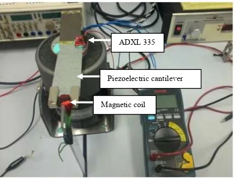
For this study, ADXL 335 as shown in Fig.4 was used to measure the acceleration in X, Y and Z axes with a minimum full-scale range of ±3 g. ADXL 335 has a number of attractive features which are small, thin and required low power. In this experiment, only one of the acceleration values is used to evaluate the output power. Level of acceleration that frequently used in industries is < 1 g-level [3]. Therefore, in the following experiment, a frequency of 76.2 Hz at around 1g (9.81 m/s2) is being use to investigate the output voltage of the energy harvesting circuits.
A range of external resistive load of 10 Ω to 1000kΩ is connected to the terminal of the energy harvesting circuit to investigate the output power, where the it can be calculated by measuring the output voltage at different value of resistive load according to Eq.2:
(2)
EM Piezo
Rectifier
Capacitor
Load
Load Rectifier
Piezo Capacitor
Load Rectifier
EM Capacitor
EM Piezo
Load Rectifier Capacitor
(a)
(b)
(c)
IEEE Student Conference on Research & Development 2013
where, P is the output power, R is the resistive load (externalresistor) and V is the output voltage.
In this experiment, there were several equipment being used include digital oscilloscope, function generator, power amplifier, electrodynamic shaker and external resistor decade box. Power amplifier is used to amplify the sine wave signal generated by function generator to the electrodynamic shaker. The sine wave signal can be control by adjusting the frequency and amplitude. The voltage output in sine wave can be observed from digital oscilloscope and root mean square value of the AC voltage is being reported.
Fig.4. Experimental set-up with piezoelectric and electromagnetic energy harvesters.
Electromative forc, e.m.f. is induced at the coil terminal when there is a change of the magnetic flux. This happens when there is mechanical movement of the magnet which attached to the tip of the cantilever. The value of induced voltage is proportional to the changing rate of magnetic flux and achieve maximum when the cantilever is at its resonant. Whilst the magnet at the tip of the cantilever can act as a proof mass to bring the resonant frequency down in this case is around 76.2 Hz.
IV. EXPERIMENT RESULTS AND DISCUSSIONS
Fig. 5 represents the results obtained from the four configurations as shown in Fig. 2 with varying resistive load from a 10 Ω up to 1 MΩ connected to the output terminal of the four configuration circuits. The electrical output is measured with a constant input of 76.2 Hz at an acceleration level of 0.03 g (0.3 m/s2).
There is no surprise to observe that the output power for energy harvester connected isolate from each other individually show an extreme performance at the top part of the graph for piezoelectric individual circuit and at the lower part of the graph is the electromagnetic when connected to rectifying circuit individually.
The maximum output power generated by piezoelectric circuit is near to 1 mW when connected to a resistive load of about 20 kΩ, whereas the maximum output power achieved by electromagnetic configuration is at only around 0.1 W when connected to a resistive load of 40 Ω. When both of these energy harvesters connected either in series or parallel, the performance seems compensating each other with output power falls in between the range of output power when each of the energy harvester isolated from each other.
When connected in series, the maximum output power the circuit can generate is around 300 W which is reduced to a factor of 3 compare to when piezoelectric connected individually. Whereas, in parallel configuration, the maximum output power increase to a factor of 3 from about 0.1 W to 0.3 W when compared to electromagnetic energy harvester connected individually.
The output voltages of the energy harvesting circuits are shown in Fig. 6. The output voltage for piezoelectric connected individually has a factor of 1.6 times greater than when both the piezoelectric and electromagnetic connected in series. Whereas the output voltage for electromagnetic when connected in parallel is about 2.5 times greater than when electromagnetic energy harvester connected individually.
In order to compare the performance of the energy harvesting circuits, all the four configurations are tested to charge a 16 V capacitor with capacitance of 3300 F. It took about 135 s for piezoelectric energy harvester to charge up to 3V compared to a charging time of 150s achieved by both piezoelectric and electromagnetic when connected in series. There is no significant increment of voltage charging by either electromagnetic energy harvester connected individually or when both energy harvesters connected in parallel within the time taken up to 250 s or around 4 minutes.
From the experimental results, it was verified that for a successful hybrid system, piezoelectric and electromagnetic energy harvesters need to be isolated. They need to be rectified individually, DC-DC step-up for electromagnetic output and DC-DC step-down for piezoelectric output before going into common storage circuit.
V. CONCLUSION
This work has reported four different configurations of energy harvesting circuits; piezoelectric connected individually, electromagnetic connected individually, piezoelectric and electromagnetic energy harvesters connected in series and in parallel. It has verified in the experimental results that piezoelectric and electromagnetic energy harvesters have to be isolated. They need to be rectified individually and DC-DC converted before feeding into common storage circuit for optimum application. From the experimental output the maximum power output generated by individual piezoelectric circuit is about 3 times greater than when connecting in series with electromagnetic energy harvester. Whereas the output power from parallel connection ADXL 335
Piezoelectric cantilever
IEEE Student Conference on Research & Development 2013
Fig. 5. Output power as a function of resistive load for different configurations of energy harvester circuits.
0.001
Fig. 6. Output voltage as a function of resistive load for different configurations of energy harvester circuits.
0
Fig. 7. Comparison of charging time for the four different configuration of energy harvester circuits.
ACKNOWLEDGMENT
The authors would like to thank the Ministry of Higher Education for the research grant, PRGS/2011/FKEKK/TK02/1 – T00001, as well as Universiti Teknikal Malaysia Melaka for CoE short term research grant PJP/2012/CeTRI/Y00001, Advanced Sensors and Embedded Control Research Group, Centre for Telecommunication Research and Innovation for supporting the research and sponsoring the presentation of this article.
REFERENCES
[1] C. K. Wei and G. Ramasamy “A hybrid energy harvesting system for small battery powered applications,” IEEE Conference on Sustainable Utilization and Development in Engineering and Technology, pp. 165– 170, 20-21 Oct 2011.
[2] N. Carolina and J. M. Conrad, “A Survey of Energy Harvesting Sources for Embedded Systems”, In proceeding of IEEE Southeastcon, 2008. [3] M. F. Ab Rahman, and S.L, Kok, “Investigation of useful ambient
vibration sources for the application of energy harvesting,” IEEE Student Conference on Research and Development (SCOReD), pp. 391–396, 19-20 Dec 2011.
[4] A. Khaligh, S. Member, P. Zeng, S. Member, and C. Zheng, “Kinetic
Energy Harvesting Using Piezoelectric and Electromagnetic Technologies — State of the Art,” IEEE Transc. on Industrial Electronics vol. 57, no. 3, pp. 850–860, 2010
[5] L. Beker and A. Muhtaroğlu, “Hybrid Energy Harvesting From Keyboard,” International Conference on Energy Aware Computing (ICEAC), pp. 1-4, Nov. 30-Dec 2, 2011.
[6] Y. Sang, X. Huang, H. Liu, and P. Jin, “A Vibration-Based Hybrid Energy Harvester for Wireless Sensor Systems,” IEEE Transactions on Magnetics, vol. 48, no. 11, pp. 4495–4498, Nov. 2012.
[7] S. Chen, “Experimental study of a hybrid vibration energy harvesting mechanism,” Symposium on Piezoelectric, Acoustic Waves and Device Application (SPAWDA), pp. 56-59, 9-11 Dec 2011.