Designing Artificial Magnetic Conductor at
2.45 GHz for Metallic Detection in RFID
Tag Application
1
Maisarah Abu, 1Eryana Eiyda Hussin, 1Mohd Saari Mohd Isa, 1Zahriladha Zakaria,
2
Zikri Abadi Baharudin, 1
Hang Tuah Jaya, 76100 Durian Tunggal, Melaka, Malaysia
Faculty of Electronic and Computer Engineering, Universiti Teknikal Malaysia Melaka,
[email protected] [email protected]
[email protected] [email protected]
2
Hang Tuah Jaya, 76100 Durian Tunggal, Melaka, Malaysia Faculty of Electrical Engineering, Universiti Teknikal Malaysia Melaka,
Abstract: In this paper, three types of AMC with different shape and design is discussed. The single unit cell Halfring AMC designed in this paper had increased the bandwidth up to 9.46%. Parametric studies were conducted for those three AMCs to investigate the effect of varying the parameters of each design. The values of gain, directivity and return loss for all AMCs is discussed and compared. From the simulated result, when the dipole is attached on Perfect Electric Conductor, PEC the performance of antenna will drop severely. The new Halfring AMC designed in this paper had overcome the problem of metallic object detection in RFID tag application. The simulated result shows that the Halfring AMC at half-lambda size had increased the performance of dipole antenna with return loss = -22.60 dB, gain = 7.58 dB and directivity of 8.15 dBi.
Keyword - Artificial Magnetic Conductor, Radio Frequency Identification, Incidence Angle
I. INTRODUCTION
The metamaterial structure has been used in to improve the performance of dipole-type antenna. Metamaterial are artificially structure that are realized by embedding metallic material with periodic pattern onto the dielectric substrate [1-3]. Electromagnetic Band Gap (EBG), Frequency Selective Surface (FSS) and Artificial Magnetic Conductor (AMC) are the term that usually been used for metamaterial structure [4]. In this paper, the characteristics of AMC over dipole antenna that represent as the Radio Frequency Identification (RFID) tag will be discussed. AMC is also known as High-Impedance Structure (HIS) because of its characteristic of having very high surface impedance (≥ 1 000 Ω) at resonant frequency. At this state, the AMC is considered as an open circuit or lossless structure. The characteristic of AMC can be observed by the reflection graph where the phase of pointed at zero degree with magnitude = +1 when at resonance state [5-6]. The AMC is designed to reduce the effect of surface wave by removing the unwanted radiation caused by the finite ground plane. The wasted power at backlobe is reduced and its smoother radiation pattern. AMC has an in-phase properties that will consequently cancelled out the current from the source with its image current. Therefore, the antenna can radiate properly due to its poor impedance matching [7-9].
This issue can be solved by introducing air gap at quarter wavelength (λ/4) between the RFID tag and the object [11-13].
Figure 1: Communication between RFID reader antenna and RFID Tag A, B and C.
Figure 1 illustrates three RFID tags at different situation. Tag A shows successful communication to/from the RFID reader antenna because Tag A is within the transmission area. While Tag C positioned out of the transmission area do not receive the signal from the RFID reader antenna will stay un-active. For Tag B the existence of metallic object had reflected most of the signal transmitted by the RFID reader antenna. So the tag cannot powered up and failed to operates even though it still in transmission area. In this paper, the new AMC structure will be designed to overcome the metal object detection by the RFID tag by removing the unwanted radiation and redirect back the surface wave. Dual-band AMC with slotted rectangular have been proposed in [14] by using Taconic TLC-32 for 0.92 GHz and 2.45 GHz frequency by introducing I-shaped slot into the rectangular patch with dimension of 62 mm x 30 mm x 6.35 mm. The designed AMC has improved 33.4 % and 35.6 % the reading distance and 70.2% and 75.7% gain of the meandered dipole antenna at 0.92 GHz and 2.45 GHz frequency respectively.
II. SINGLE CELL STRUCTURE
In this paper, three AMC designs with different shape and dimension will be discussed. Figure 2 shows all
those three AMCs designed by using Rogers RO3003 with thickness 1.52 mm and εr = 3 at frequency of 2.45
GHz. The bandwidth is the important parameter to be studied in single unit cell AMC design. It can be calculated by taking the value of reflection phase at ±90° and the resonant frequency must fall at 2.45 GHz at zero degree.
(a) (c)
Figure 2: (a) Square (b) Rectangular (c) Halfring AMC where m = 29 mm, n = 4 mm, p = 0.5 mm, q = 1.5 mm, r = 1 mm, (b)
Transmission area RFID Tag A
RFID Tag C
RFID Tag B
Metal object RFID Reader Antenna
Transmit
Frequency (GHz)
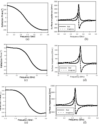
Figure 3: (a) Reflection phase (b) surface impedance of Square AMC, (c) reflection phase (d) surface impedance of Rectangular AMC, (e) reflection phase and (f) surface impedance of Halfring AMC
Throughout the results in Figure 3 shows that all the AMCs satisfy the characteristic of single unit cell AMC. Firstly, the basic Square AMC is designed with dimension of width and height = 32 mm. From the reflection phase in Figure 3(a), the calculated bandwidth is 8.36%. Then, by maintaining the same width, the Rectangular AMC is designed with height = 4 mm (86.8% smaller than Square AMC). The calculated bandwidth of Rectangular AMC is decreased to 7.52%. Next, the Halfring AMC is designed on rectangular substrate with additional vertical and horizontal gap introduced into the structure. The calculated bandwidth of Halfring AMC illustrated in Figure 2 (c) is increased 13.86% of frequency with overall size of 31.3 mm x 6.3 mm.
Frequency (GHz)
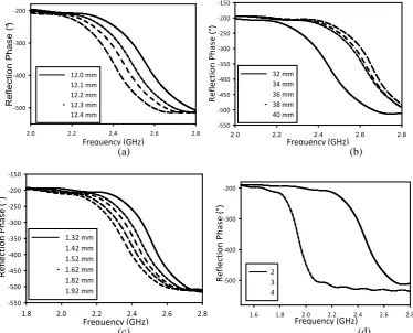
Figure 4: Parametric study on square parameter (a) gap (b) width (c) thickness (d) substrate dielectric constant
For Rectangular AMC, only two parameter studies were conducted. It is because the thickness and permittivity of substrate used in this design will remain constant. In Figure 5(a), when the gap is increased, the frequency will increase too. Therefore, small gap will be used in this design. In Figure 5(b) shows that small increments in rectangular PEC patch height gives higher resonant frequency with decreased bandwidth.
Frequency (GHz)
Figure 5: Parametric study on rectangular AMC (a) gap (b) height
Frequency (GHz)
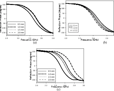
Figure 6: Parametric study on varying the parameter (a) p, (b) q and (c) gap around the halfring patch.
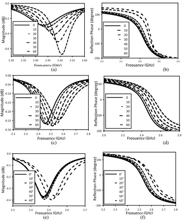
III.INCIDENCE ANGLE
Frequency (GHz)
2.30 2.35 2.40 2.45 2.50 2.55 2.60
M
Figure 8: Result of varying the incidence of angle to (a) and (b)Square AMC (c) and (d) Rectangular AMC (e) and (f) Halfring AMC
IV.AMC WITH DIPOLE ANTENNA
Frequency (GHz)
with Square AMC ground plane of 64 mm x 64 mm with Square AMC ground plane of 128 mm x 32 mm with PEC ground plane
0
with Square AMC ground plane of 64 mm x 64 mm with Square AMC ground plane of 128 mm x 32 mm with PEC ground plane
(a) (b)
with Rectangular AMC ground plane of 62 mm x 62 mm with Rectangular AMC ground plane of 32 mm x 32 mm with PEC ground plane
0
with PEC ground plane
with Rectangular AMC ground plane of 64 mm x 64 mm with Rectangular AMC ground plane of 32 mm x 32 mm
(c) (d)
Frequency (GHz)
2.40 2.42 2.44 2.46 2.48 2.50
R
with halfring AMC ground plane of 62.9 mm x 62.9 mm
0
V. RESULT AND DISCUSSION
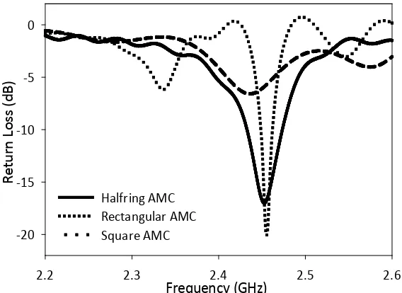
Table 2 shows the simulated result for each AMC which have optimized with dipole antenna discussed in part 4. From the Table 2, the Halfring AMC shows better result in return loss, gain and directivity when attached to the dipole antenna at 2.45 GHz. From the simulation result for each AMC, the bigger size of single unit cell arrangement gives better result. The directivity of each AMC is not much increased but still, the Halfring AMC shows the highest directivity than the others. By taking the consideration for all single unit cell AMCs arrangement, the result for AMC with size of half-lambda (which is closed to 61.22 mm) are combined and discussed. Figure 10 shows the result of return loss value for Square, Rectangular and Halfring AMC at 2.45 GHz. The rectangular shows give the highest value but the value of gain is too low. Halfring AMC shows good return loss than the Square AMC and wider bandwidth than the Rectangular AMC. The detailed comparison result for AMC in Figure 10 is shown in Table 3. Next, the reading distance of the optimized Halfring AMC is measured by using the actual RFID tag from industry. The measurement of reading range using the standard RFID system shows that the longest reading distance of 3.4 meter. When metal object is attached onto the RFID tag, the reader failed to read the tag even at zero distance. When the Halfring AMC is placed between the metal object and RFID Tag the reading distance is measured at 2.5 meter. So this means that Halfring AMC had overcome the problem of metal object detection for RFID Tag at 2.45 GHz.
Frequency (GHz)
2.2 2.3 2.4 2.5 2.6
R
e
tu
rn
L
o
ss
(
d
B
)
-20 -15 -10 -5 0
Halfring AMC Rectangular AMC Square AMC
Figure 10: Return Loss for optimized Square, Rectangular and Halfring AMC for half-lambda size.
Table 2: Simulation result for AMCs with dipole antenna
AMC Size (mm x
mm)
Arrangement Return Loss
(dB)
Gain (dB) Directivity (dBi)
Square 64 x 64 2 x 2 -6.57 5.93 7.83
128 x 32 4 x 1 -8.48 7.83 7.35
Rectangular 32 x 32 16 x 2 -7.20 1.22 5.25
62 x 62 8 x 1 -19.18 2.14 5.92
Halfring 62.9 x 62.9 9 x 2 -16.92 7.45 7.86
130 x 130 18 x 4 -22.60 7.51 8.14
Table 3: Simulation result for Square, Rectangular and Halfring AMC at half-lambda size (≈61.22 mm x 61.22 mm)
Square AMC Rectangular
AMC
Halfring AMC
Return Loss, dB -6.57 -19.19 -16.94
Gain, dB 5.94 6.48 7.58
VI CONCLUSION
For the conclusion, the Halfring AMC proposed in this paper can be used to overcome the problem of metallic object detection in RFID application. The optimized Halfring AMC with 130 mm x 130 mm size shows better return loss value of -22.60 dB than the Halfring AMC with 62.9 mm x 62.9 mm size. But, the differences of gain and directivity results for both size is not too far. So, the AMC with 62.9 mm x 62.9 mm size is more suitable for RFID application. The designed AMC also has potential to be used in energy harvesting application where it can be integrated with the rectenna to improve the efficiency of the system especially for long distance transmission.
ACKNOWLEDGEMENT
The authors wish to thank the Centre for Research and Innovation Management (CRIM) of Universiti Teknikal Malaysia Melaka (UTeM) for the support of this work under the grant number of PJP/2012/FKEKK (27B) S01030 and PJP/2013/FKEKK(7B)S01155.
REFERENCES
[1] Ramona Cosmina Hadarig, M. Elena de Cos, and F. Las-Heras, “UHF Dipole-AMC Combination for RFID Applications”, IEEE Antennas And Wireless Propagation Letters, VOL. 12, 2013, pp: 1041-1044.
[2] Haider R. Raad, Member, IEEE, Ayman I. Abbosh, Student Member, IEEE, Hussain M. Al-Rizzo, and Daniel G. Rucker, “Flexible and Compact AMC Based Antenna for Telemedicine Applications”, IEEE Transactions On Antennas And Propagation, Vol. 61, 2013, pp;524-531.
[3] B. S. Cook, Student Member, IEEE, and A. Shamim, Member, IEEE, “Utilizing Wideband AMC Structures for High-Gain Inkjet-Printed Antennas on Lossy Paper Substrate”, IEEE Antennas And Wireless Propagation Letters, Vol. 12, 2013, pp :76-79.
[4] D. J. Kern and D. H. Werner, “Magnetic Loading of EBG AMC Ground Planes and Ultrathin Absorbers for Improved Bandwidth”, Microwave and Optical Technology Letters, Vol. 48, No. 12, December 2006, pp: 2468–2471.
[5] J. R. Sohn, K. Y. Kim, H. –S. Tae, “Comparative Study on Various Artificial Magnetic Conductors for Low-Profile Antenna” Progress in Electromagnetics Research, PIER 61, 2006, pp:27-37.
[6] Sievenpiper D. F. “High Impedance Electromagnetic Surface” PHD Thesis, University of California at Los Angeles 1999.
[7] D. SievenpiperLijun Zhang, Romulo F. Jimenez Broas, Nicholas G. Alex´opolous, and Eli Yablonovitch, “High-Impedance Electromagnetic Surfaces with a Forbidden Frequency Band” IEEE Transactions On Microwave Theory And Techniques, Vol. 47, No. 11, November 1999, pp: 2059 – 2074.
[8] Constantin R. Simovski, Peter de Maagt, and Irina V. Melchakova, “High-Impedance Surfaces Having Stable Resonance With Respect to Polarization and Incidence Angle” IEEE Transactions On Antennas And Propagation, Vol. 53, No. 3, March 2005, pp: 908-914. [9] M. Hosseini, A. Pirhadi, and M. Hakkak, “A Novel AMC With Little Sensitivity To The Angle Of Incidence Using 2-Layer Jerusalem
Cross FSS”, Progress In Electromagnetics Research, PIER 64, 2006, pp: 43-51.
[10] Alireza Foroozesh, and Lotfollah Shafai, “Investigation Into the Application of Artificial Magnetic Conductors to Bandwidth Broadening, Gain Enhancement and Beam Shaping of Low Profile and Conventional Monopole Antennas,” IEEE Transactions On Antennas And Propagation, Vol. 59, No. 1, January 2011, pp: 4-20.
[11] D. Yan, Q. Gao and N. Yuan, “Strip-Type AMC Structure and Analysis to Its Band-Gap Characteristics” Progress in Elecromagnetics Symposium 2005, pp. 505-509, Aug 2005.
[12] E. Carrubba, A, Monorchio, and G. Manara “Artificial Magnetic Surface for Circular Polarization Movement” Microwave and Optical Technology Letters, Vol 5, pp.1782-1786, Aug 2010.
[13] M Elena de Cos, Yuri Alvarez and Fernando Las-Heras, “Design and Characteristics of Planar Artificial Magnetic Conductor in the RFID SHF Band” Proceeding of Forth European Conference on Antenna and Propagation 2010, pp. 1-5, Apr 2010.