SIX LEGGED ROBOT WALKING GAITS
LOOI SIEW CHIN
A report submitted in partial fulfillment of the requirements for the degree of Mechatronics Engineering
Faculty of Electrical Engineering
UNIVERSITI TEKNIKAL MALAYSIA MELAKA
“I hereby declare that I have read through this report entitle “Six Legged Robot Walking Gaits” and found that it has comply the partial fulfillment for awarding the degree of Bachelor of Mechatronics Engineering”
Signature :……….
Supervisor‟s Name : Dr. Ahmad Zaki bin Haji Shukor
iii
I declare that this report entitle “Six Legged Robot Walking Gaits” is the result of my own research except as cited in the references. The report has not been accepted for any degree and is not concurrently submitted in candidature of any other degree.
Signature :……….
Name : Looi Siew Chin
iv
v
ACKNOWLEDGEMENT
This final year report is made possible through the help and big support from everyone including my supervisor, family and friends.
vi
ABSTRACT
vii
ABSTRAK
viii
TABLE OF CONTENTS
CHAPTER TITLE PAGE
ACKNOWLEDGEMENT v
ABSTRACT vi
TABLE OF CONTENTS viii
LIST OF TABLES xi
LIST OF FIGURES xiii
LIST OF ABBREVIATIONS xvi
LIST OF APPENDICES xvii
1 INTRODUCTION
1.1 Motivation 1
1.2 Problem statement 2
1.3 Objectives 3
1.4 Scope 3
2 LITERATURE REVIEW
2.1 Theory and basic principle of six legged robot 4 2.1.1 Study of six legged robot 4 2.1.2 Types of walking gaits for six legged robot 5 2.1.3 Theory involved in analysis of six legged
robot
7
2.2 Previous related work 8
2.2.1 Previous works of six legged robot 8 2.2.2 Previous works of line following robot 14
2.3 Summary 17
ix
3 METHODOLOGY
3.1 Project methodology to achieve first objective 23 3.1.1 Hardware selection 24 3.1.2 Early calibration of servo motors 27 3.1.3 System integration 27 3.1.4 Preliminary analysis on hardware 30 3.1.5 Programming for six legged robot 33 3.2 Project methodology to achieve second objective 35 3.2.1 Construction of walking path for line
following task
35
3.2.2 Analysis on speed of robot to complete line following task with tripod and wave gaits
37
3.2.3 Analysis on measurement of errors from deviation of centre of robot from the line in performing line following task with tripod and wave gaits
38
3.3 Conclusion 41
4 RESULTS AND DISCUSSION
4.1 Preliminary analysis on hardware 42 4.1.1 Inverse kinematics 42 4.1.2 Size of moveable area of leg 44 4.2 Implementation of tripod and wave gaits to six
legged robot
45
4.2.1 Tripod gait 45
4.2.2 Wave gait 46
4.3 Analysis on speed of robot to complete line following task with tripod and wave gaits
47
4.3.1 Move straight 47
4.3.2 Turning at different angles 48 4.3.3 Summary of result obtained in analysis of
speed
x 4.4 Analysis on measurement of errors from deviation
of centre of robot from the line in performing line following task with tripod and wave gaits
51
4.4.1 Move straight 51
4.4.2 Turning at different angles 55 4.4.3 Summary of result obtained in analysis of
measurement of errors from deviation of centre of robot from the line
61
4.5 Summary 61
5 CONCLUSION AND RECOMMENDATION
5.1 Conclusion 63
5.2 Limitation of the project 64
REFERENCES 65
APPENDICES 69
xi
LIST OF TABLES
TABLE TITLE PAGE
2.1 Comparison of the types of design of hexapod and the performance test
17
2.2 Comparison of line following robot and the performance test
20
3.1 Comparison different design of hexapod hardware 24
3.2 Specifications of servo motor used 26
3.3 Calculation of rotation angle of servo motor from the position to turn
33
3.4 Line following algorithm 34
3.5 Results for time taken to complete 1 cycle (move straight)
37
3.6 Results for time taken to complete 1 cycle (turning at different angles)
37
3.7 Algorithm of LDR circuit in differentiate the error (centre of robot fall on line)
39
3.8 Algorithm of LDR circuit in differentiate the error (centre of robot out from line)
40
3.9 Number of occurrence of centre of robot at different location on or out from line
40
4.1 Results for time taken to complete 1 cycle (move straight)
47
4.2 Results for time taken to complete 1 cycle (turning at different angles)
48
4.3 Number of occurrence of centre of robot at different location on or out from line (tripod gait)
52
4.4 Number of occurrence of centre of robot at different location on or from line (wave gait)
xii 4.5 Number of occurrence of centre of robot at different
location on or from line (turning angle of 30˚)
55
4.6 Number of occurrence of centre of robot at different location on or from line (turning angle of 45˚)
56
4.7 Number of occurrence of centre of robot at different location on or from line (turning angle of 60˚)
57
4.8 Number of occurrence of centre of robot at different location on or from line (turning angle of 30˚)
58
4.9 Number of occurrence of centre of robot at different location on or from line (turning angle of 45˚)
59
4.10 Number of occurrence of centre of robot at different location on or from line (turning angle of 60˚)
60
4.11 Summary for analysis of speed and analysis of error measurement
xiii
LIST OF FIGURES
FIGURE TITLE PAGE
1.1 DASH with wings 1
2.1 The placement of legs for rectangular hexapod 5 2.2 The placement of legs for hexagonal hexapod 5
2.3 Structure of leg for ant 5
2.4 The leg arrangement for a hexagonal hexapod 6 2.5 The moving sequence of legs in wave gait 6 2.6 Design of hexapod with wall following behaviour 9 2.7 Construction of line following hexapod robot 9
2.8 18 DOF hexapod used in [13] 10
2.9 Fuzzy sets for each of three inputs 10
2.10 Schematic of reinforcement learning algorithm for hexapod
11
2.11 Configuration of single leg 12
2.12 Coordinate frame of kinematics for a single leg 12
2.13 Virtual model of hexapod in Matlab 13
2.14 Torque reading of each motor on different legs when perform tripod gait
14
2.15 Arrangement of sensor 15
2.16 Position of sensors 15
2.17 Arrangement of sensors 15
2.18 Different curve and cycle 16
3.1 Flow chart for methodology (overall) 22
3.2 Project methodology flowchart to achieve objective 1 23
3.3 Six legged robot used in project 25
3.4 Servotor32 controller 25
3.5 Connection of servo motor 26
xiv
3.7 Structure of hexapod 27
3.8 Leg of robot 28
3.9 Block diagram of line following task 28
3.10 Six legged robot after implemented line following circuit
29
3.11 Position of IR sensors 29
3.12 Leg structure of robot 30
3.13 The maximum and minimum radius for reachable area of robot‟s leg
32
3.14 Project methodology flowchart to achieve second objective
35
3.15 Straight line path for robot 35
3.16 Path with turning angle of 30˚, (b) Path with turning angle of 45˚, (c) Path with turning angle of 60˚
36
3.17 LDR circuit 38
3.18 Centre on line 39
3.19 Centre on line 39
3.20 Centre on line 39
3.21 Centre on line 39
3.22 Centre out from line 40
3.23 Centre out from line 40
3.24 Centre out from line 40
4.1 Joint variable on a single leg 43
4.2 Size of moveable area of leg 44
4.3 Movement of legs in tripod gait 45
4.4 Movement of legs in wave gait 46
4.5 Graph of speed of robot in completing the path versus turning angle for tripod and wave gaits
49
4.6 The position of centre of robot with respect to line (tripod gait)
51
4.7 Number of occurrence of centre of robot on the region of line (tripod)
xv 4.8 The position of centre of robot with respect to line
(wave gait)
53
4.9 Number of occurrence of centre of robot on the region of line (wave)
54
4.10 The position of centre of robot with respect to line (turning angle = 30˚)
55
4.11 The position of centre of robot with respect to line (turning angle = 45˚)
56
4.12 The position of centre of robot with respect to line (turning angle = 60˚)
57
4.13 The position of centre of robot with respect to line (turning angle = 30˚)
58
4.14 The position of centre of robot with respect to line (turning angle = 45˚)
59
4.15 The position of centre of robot with respect to line (turning angle = 60˚)
xvi
LIST OF ABBREVIATIONS
PWM - Pulse width modulation DOF - Degree of freedom
m - meter
mm - millimetre
Nm - Newton per meter
L - Length
W - Width
H - Height
V - Volt
g - grams
kg/cm - kilograms per centimetre ms - milliseconds
cm - centimetre IR - infrared
xvii
LIST OF APPENDICES
APPENDIX TITLE PAGE
A Gantt chart for Final Year Project 69 B Program for early calibration of servo motors 71
CHAPTER 1
INTRODUCTION
In this chapter, motivation, problem statement, objective and the scope of the project will be presented.
1.1 Motivation
Legged robots have more advantages compared to wheeled robots. Legged robots are suitable for both even and uneven surfaces, while wheeled robots are designed to operate in even surface. Legged robots also help human in exploring the animal locomotion such as study of inserts‟ locomotion from the construction of hexapod robot. Legged robots also manage to avoid obstacles by step over them while wheeled robots only manage to take another path to avoid the obstacles [1]. For legged robot, the stability is increased as the number of legs of robot is increased. Six legged robot also known as hexapod is a robot that is statically stable and can walk in unstructured terrain. According to [1], the hexapod robot concept is used in rescue job where it used to find the earthquake survivors. The hexapod robot designed or also known as Dynamic Autonomous Sprawled Hexapod (DASH) is inspired by structure of cockroach was designed to survive in unstable condition. DASH able to climb between the fallen buildings after earthquake to find survivors as a camera is mounted on the body of robot [1].
2 Figure 1.1 shows the latest design of DASH which wings are applied on the hexapod robot. The hexapod structure enables DASH to move in uneven terrain and launches the feet on a stable position when descending from a high position [1].
It has different walking gaits that gave it an advantage in performing different kind of applications. However, different walking gaits can formed different locomotions of hexapod although it is performing a same task. Hence, the walking gaits analysis of a hexapod in completing a task is crucial to maintain the well performance of hexapod although different gaits are applied.
1.2 Problem statement
3
1.3 Objectives
The objectives for conducting this project are:
1) To implement line following behaviour to the hexapod with tripod gait and wave gait.
2) To analyse the speed and measure the errors from deviation of centre of robot from the line in performing line following task with tripod gait and wave gait.
1.4 Scope
CHAPTER 2
LITERATURE REVIEW
This chapter presents about some basic principles and theories involved in the project and review of previous works about the design of six legged robot and the method to analyse its performance as well as some designs of line following robot and method to analyse its performance.
2.1 Theory and basic principle of six legged robot
In this section, the basic principles such as the shape of body and leg structure of six legged robot and types of walking gaits that involved in six legged robot are discussed. The theory involved in analysis of six legged robot will presented in this section as well.
2.1.1 Study of six legged robot
5
Figure 2.1: The placement of legs for rectangular hexapod [3]
Figure 2.2: The placement of legs for hexagonal hexapod [3]
The construction of the hexapod is inspired by the body structure of insect. There are four main segments for general insect‟s leg which is coxa, femur, tibia and tarsus. From the leg structure of insect, hexapod is created with each leg has 3 degree of freedom.
Figure 2.3: Structure of leg for ant [4]
2.1.2 Type of walking gaits for six legged robot
6
2.1.2.1 Tripod gait
Tripod gait is considered as the most well-known gait for a hexapod. In this type of gait, three legs remained on the ground to support while another three legs are lift up and swing to move forward [5].
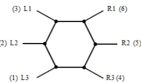
Figure 2.4: The leg arrangement for a hexagonal hexapod
Based on Figure 2.4, when the hexapod is moving forward, L1, L3 and R2 will lift up and swing towards forward, while L2, R1 and R3 will remain on ground and push the body to forward. Another leg configuration can be L2, R1 and R3 raised and swing forward, L1, L3 and R2 remained on ground and push forward.
2.1.2.2 Wave gait
Wave gait is considered as the most stable type of walking gait in hexapod. All legs on one side will move forward, followed by the opposite side. For the walking mechanism, one leg will only lift up on each time, while the other five remained on the ground. Based on Figure 2.5, the robot moves forward by raises up L3, swing forward L3 and put down L3, followed by L2, L1, R3, R2, R1. This type of walking mechanism is based on the movement of an insect to move forward [6].
7
2.1.3 Theory involved in analysis of six legged robot
This part describes about the term that used in analysis part of robot.
2.1.3.1 Degree of Freedom
Degree of freedom (DOF) is important in the study of robotics. Degree of freedom can be referred as the ability of an object to move in a single direction independently. The number of degree of freedom is normally known as the number of component required to create motion. The motion generated can be divided into two types which are translational and rotational degree of freedom [7].
2.1.3.2 Stability
Stability is crucial in movement of robot. It can be divided into two types which are static (stand without falling) and dynamic (moving without falling) [8]. Static stability defined as the robot is stable when no motion of robot is required. A robot needs to have a minimum of four legs to achieve static stability. The static stability can be achieved by the mechanical design of the robot which is the structure of the robot itself. Dynamic stability is achieved by control of robot such as the movement of legs of robot [9].
2.1.3.3 Duty factor
Gait can be classified according to its duty factor, . The duty factor is in range of 0 to 1 and it can be defined as the ratio between leg stand duration and the cycle time [10].
sw st st T T T (2.1)
where, Tst Duration of foot is standing on ground
sw
![Figure 1.1: DASH with wings [1]](https://thumb-ap.123doks.com/thumbv2/123dok/487989.53717/18.595.230.380.649.748/figure-dash-with-wings.webp)
![Figure 2.1: The placement of legs for rectangular hexapod [3]](https://thumb-ap.123doks.com/thumbv2/123dok/487989.53717/22.595.250.359.397.508/figure-placement-legs-rectangular-hexapod.webp)